pH measurement
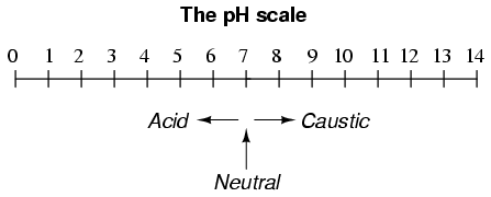
A very important measurement in many liquid chemical processes (industrial, pharmaceutical, manufacturing, food production, etc.) is that of pH: the measurement of hydrogen ion concentration in a liquid solution. A solution with a low pH value is called an "acid," while one with a high pH is called a "caustic." The common pH scale extends from 0 (strong acid) to 14 (strong caustic), with 7 in the middle representing pure water (neutral):
pH is defined as follows: the lower-case letter "p" in pH stands for the negative common (base ten) logarithm, while the upper-case letter "H" stands for the element hydrogen. Thus, pH is a logarithmic measurement of the number of moles of hydrogen ions (H+) per liter of solution. Incidentally, the "p" prefix is also used with other types of chemical measurements where a logarithmic scale is desired, pCO2 (Carbon Dioxide) and pO2 (Oxygen) being two such examples.
The logarithmic pH scale works like this: a solution with 10-12 moles of H+ ions per liter has a pH of 12; a solution with 10-3 moles of H+ ions per liter has a pH of 3. While very uncommon, there is such a thing as an acid with a pH measurement below 0 and a caustic with a pH above 14. Such solutions, understandably, are quite concentrated and extremely reactive.
While pH can be measured by color changes in certain chemical powders (the "litmus strip" being a familiar example from high school chemistry classes), continuous process monitoring and control of pH requires a more sophisticated approach. The most common approach is the use of a specially-prepared electrode designed to allow hydrogen ions in the solution to migrate through a selective barrier, producing a measurable potential (voltage) difference proportional to the solution's pH:

The design and operational theory of pH electrodes is a very complex subject, explored only briefly here. What is important to understand is that these two electrodes generate a voltage directly proportional to the pH of the solution. At a pH of 7 (neutral), the electrodes will produce 0 volts between them. At a low pH (acid) a voltage will be developed of one polarity, and at a high pH (caustic) a voltage will be developed of the opposite polarity.
An unfortunate design constraint of pH electrodes is that one of them (called the measurement electrode) must be constructed of special glass to create the ion-selective barrier needed to screen out hydrogen ions from all the other ions floating around in the solution. This glass is chemically doped with lithium ions, which is what makes it react electrochemically to hydrogen ions. Of course, glass is not exactly what you would call a "conductor;" rather, it is an extremely good insulator. This presents a major problem if our intent is to measure voltage between the two electrodes. The circuit path from one electrode contact, through the glass barrier, through the solution, to the other electrode, and back through the other electrode's contact, is one of extremely high resistance.
The other electrode (called the reference electrode) is made from a chemical solution of neutral (7) pH buffer solution (usually potassium chloride) allowed to exchange ions with the process solution through a porous separator, forming a relatively low resistance connection to the test liquid. At first, one might be inclined to ask: why not just dip a metal wire into the solution to get an electrical connection to the liquid? The reason this will not work is because metals tend to be highly reactive in ionic solutions and can produce a significant voltage across the interface of metal-to-liquid contact. The use of a wet chemical interface with the measured solution is necessary to avoid creating such a voltage, which of course would be falsely interpreted by any measuring device as being indicative of pH.
Here is an illustration of the measurement electrode's construction. Note the thin, lithium-doped glass membrane across which the pH voltage is generated:

Here is an illustration of the reference electrode's construction. The porous junction shown at the bottom of the electrode is where the potassium chloride buffer and process liquid interface with each other:

The measurement electrode's purpose is to generate the voltage used to measure the solution's pH. This voltage appears across the thickness of the glass, placing the silver wire on one side of the voltage and the liquid solution on the other. The reference electrode's purpose is to provide the stable, zero-voltage connection to the liquid solution so that a complete circuit can be made to measure the glass electrode's voltage. While the reference electrode's connection to the test liquid may only be a few kilo-ohms, the glass electrode's resistance may range from ten to nine hundred mega-ohms, depending on electrode design! Being that any current in this circuit must travel through both electrodes' resistances (and the resistance presented by the test liquid itself), these resistances are in series with each other and therefore add to make an even greater total.
An ordinary analog or even digital voltmeter has much too low of an internal resistance to measure voltage in such a high-resistance circuit. The equivalent circuit diagram of a typical pH probe circuit illustrates the problem:
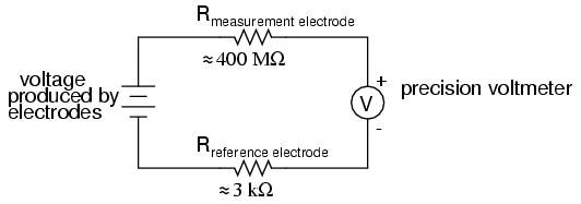
Even a very small circuit current traveling through the high resistances of each component in the circuit (especially the measurement electrode's glass membrane), will produce relatively substantial voltage drops across those resistances, seriously reducing the voltage seen by the meter. Making matters worse is the fact that the voltage differential generated by the measurement electrode is very small, in the millivolt range (ideally 59.16 millivolts per pH unit at room temperature). The meter used for this task must be very sensitive and have an extremely high input resistance.
The most common solution to this measurement problem is to use an amplified meter with an extremely high internal resistance to measure the electrode voltage, so as to draw as little current through the circuit as possible. With modern semiconductor components, a voltmeter with an input resistance of up to 1017 Ω can be built with little difficulty. Another approach, seldom seen in contemporary use, is to use a potentiometric "null-balance" voltage measurement setup to measure this voltage without drawing any current from the circuit under test. If a technician desired to check the voltage output between a pair of pH electrodes, this would probably be the most practical means of doing so using only standard benchtop metering equipment:
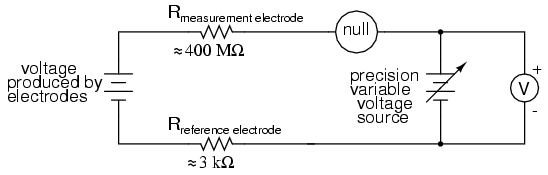
As usual, the precision voltage supply would be adjusted by the technician until the null detector registered zero, then the voltmeter connected in parallel with the supply would be viewed to obtain a voltage reading. With the detector "nulled" (registering exactly zero), there should be zero current in the pH electrode circuit, and therefore no voltage dropped across the resistances of either electrode, giving the real electrode voltage at the voltmeter terminals.
Wiring requirements for pH electrodes tend to be even more severe than thermocouple wiring, demanding very clean connections and short distances of wire (10 yards or less, even with gold-plated contacts and shielded cable) for accurate and reliable measurement. As with thermocouples, however, the disadvantages of electrode pH measurement are offset by the advantages: good accuracy and relative technical simplicity.
Few instrumentation technologies inspire the awe and mystique commanded by pH measurement, because it is so widely misunderstood and difficult to troubleshoot. Without elaborating on the exact chemistry of pH measurement, a few words of wisdom can be given here about pH measurement systems:
- All pH electrodes have a finite life, and that lifespan depends greatly on the type and severity of service. In some applications, a pH electrode life of one month may be considered long, and in other applications the same electrode(s) may be expected to last for over a year.
- Because the glass (measurement) electrode is responsible for generating the pH-proportional voltage, it is the one to be considered suspect if the measurement system fails to generate sufficient voltage change for a given change in pH (approximately 59 millivolts per pH unit), or fails to respond quickly enough to a fast change in test liquid pH.
- If a pH measurement system "drifts," creating offset errors, the problem likely lies with the reference electrode, which is supposed to provide a zero-voltage connection with the measured solution.
- Because pH measurement is a logarithmic representation of ion concentration, there is an incredible range of process conditions represented in the seemingly simple 0-14 pH scale. Also, due to the nonlinear nature of the logarithmic scale, a change of 1 pH at the top end (say, from 12 to 13 pH) does not represent the same quantity of chemical activity change as a change of 1 pH at the bottom end (say, from 2 to 3 pH). Control system engineers and technicians must be aware of this dynamic if there is to be any hope of controlling process pH at a stable value.
- The following conditions are hazardous to measurement (glass) electrodes: high temperatures, extreme pH levels (either acidic or alkaline), high ionic concentration in the liquid, abrasion, hydrofluoric acid in the liquid (HF acid dissolves glass!), and any kind of material coating on the surface of the glass.
- Temperature changes in the measured liquid affect both the response of the measurement electrode to a given pH level (ideally at 59 mV per pH unit), and the actual pH of the liquid. Temperature measurement devices can be inserted into the liquid, and the signals from those devices used to compensate for the effect of temperature on pH measurement, but this will only compensate for the measurement electrode's mV/pH response, not the actual pH change of the process liquid!
Advances are still being made in the field of pH measurement, some of which hold great promise for overcoming traditional limitations of pH electrodes. One such technology uses a device called a field-effect transistor to electrostatically measure the voltage produced by an ion-permeable membrane rather than measure the voltage with an actual voltmeter circuit. While this technology harbors limitations of its own, it is at least a pioneering concept, and may prove more practical at a later date.
- REVIEW:
- pH is a representation of hydrogen ion activity in a liquid. It is the negative logarithm of the amount of hydrogen ions (in moles) per liter of liquid. Thus: 10-11 moles of hydrogen ions in 1 liter of liquid = 11 pH. 10-5.3 moles of hydrogen ions in 1 liter of liquid = 5.3 pH.
- The basic pH scale extends from 0 (strong acid) to 7 (neutral, pure water) to 14 (strong caustic). Chemical solutions with pH levels below zero and above 14 are possible, but rare.
- pH can be measured by measuring the voltage produced between two special electrodes immersed in the liquid solution.
- One electrode, made of a special glass, is called the measurement electrode. It's job it to generate a small voltage proportional to pH (ideally 59.16 mV per pH unit).
- The other electrode (called the reference electrode) uses a porous junction between the measured liquid and a stable, neutral pH buffer solution (usually potassium chloride) to create a zero-voltage electrical connection to the liquid. This provides a point of continuity for a complete circuit so that the voltage produced across the thickness of the glass in the measurement electrode can be measured by an external voltmeter.
- The extremely high resistance of the measurement electrode's glass membrane mandates the use of a voltmeter with extremely high internal resistance, or a null-balance voltmeter, to measure the voltage.