Selsyn (synchro) motors
Normally, the rotor windings of a wound rotor induction motor are shorted out after starting. During starting, resistance may be placed in series with the rotor windings to limit starting current. If these windings are connected to a common starting resistance, the two rotors will remain synchronized during starting. (Figure below) This is usefull for printing presses and draw bridges, where two motors need to be synchronized during starting. Once started, and the rotors are shorted, the synchronizing torque is absent. The higher the resistance during starting, the higher the synchronizing torque for a pair of motors. If the starting resistors are removed, but the rotors still paralleled, there is no starting torque. However there is a substantial synchronizing torque. This is a selsyn, which is an abbreviation for “self synchronous”.
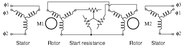
Starting wound rotor induction motors from common resistors.
The rotors may be stationary. If one rotor is moved through an angle θ, the other selsyn shaft will move through an angle θ. If drag is applied to one selsyn, this will be felt when attempting to rotate the other shaft. While multi-horsepower (multi-kilowatt) selsyns exist, the main appplication is small units of a few watts for instrumentation applications– remote position indication.
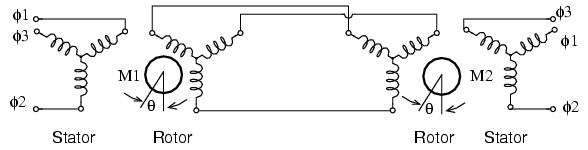
Selsyns without starting resistance.
Instrumentation selsyns have no use for starting resistors. (Figure above) They are not intended to be self rotating. Since the rotors are not shorted out nor resistor loaded, no starting torque is developed. However, manual rotation of one shaft will produce an unbalance in the rotor currents until the parallel unit's shaft follows. Note that a common source of three phase power is applied to both stators. Though we show three phase rotors above, a single phase powered rotor is sufficient as shown in Figure below.
Transmitter - receiver
Small instrumentation selsyns, also known as sychros, use single phase paralleled, AC energized rotors, retaining the 3-phase paralleled stators, which are not externally energized. (Figure below) Synchros function as rotary transformers. If the rotors of both the torque transmitter (TX) and torque receiver (RX) are at the same angle, the phases of the induced stator voltages will be identical for both, and no current will flow. Should one rotor be displaced from the other, the stator phase voltages will differ between transmitter and receiver. Stator current will flow developing torque. The receiver shaft is electrically slaved to the transmitter shaft. Either the transmitter or receiver shaft may be rotated to turn the opposite unit.
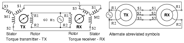
Synchros have single phase powered rotors.
Synchro stators are wound with 3-phase windings brought out to external terminals. The single rotor winding of a torque transmitter or receiver is brough out by brushed slip rings. Synchro transmitters and receivers are electrically identical. However, a synchro receiver has inertial damping built in. A synchro torque transmitter may be substituted for a torque receiver.
Remote position sensing is the main synchro application. (Figure below) For example, a synchro transmitter coupled to a radar antenna indicates antenna position on an indicator in a control room. A synchro transmitter coupled to a weather vane indicates wind direction at a remote console. Synchros are available for use with 240 Vac 50 Hz, 115 Vac 60 Hz, 115 Vac 400 Hz, and 26 Vac 400 Hz power.
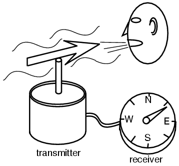
Synchro application: remote position indication.
Differential transmitter - receiver
A synchro differential transmitter (TDX) has both a three phase rotor and stator. (Figure below) A synchro differential transmitter adds a shaft angle input to an electrical angle input on the rotor inputs, outputting the sum on the stator outputs. This stator electrical angle may be displayed by sending it to an RX. For example, a synchro receiver displays the position of a radar antenna relative to a ship's bow. The addition of a ship's compass heading by a synchro differential transmitter, displays antenna postion on an RX relative to true north, regardless of ship's heading. Reversing the S1-S3 pair of stator leads between a TX and TDX subtracts angular positions.
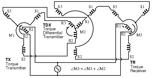
Torque differential transmitter (TDX).
A shipboard radar antenna coupled to a synchro transmitter encodes the antenna angle with respect to ship's bow. (Figure below) It is desired to display the antenna position with respect to true north. We need to add the ships heading from a gyrocompass to the bow-relative antenna position to display antenna angle with respect to true north. ∠antenna + ∠gyro

Torque differential transmitter application: angular addition.
∠antenna-N = ∠antenna + ∠gyro
∠rx = ∠tx + ∠gy
For example, ship's heading is ∠30o, antenna position relative to ship's bow is ∠0o, ∠antenna-N is:
∠rx = ∠tx + ∠gy
∠30o = ∠30o + ∠0o
Example, ship's heading is ∠30o, antenna position relative to ship's bow is ∠15o, ∠antenna-N is:
∠45o = ∠30o + ∠15o
Addition vs subtraction
For reference we show the wiring diagrams for subtraction and addition of shaft angles using both TDX's (Torque Differential transmitter) and TDR's (Torque Differential Receiver). The TDX has a torque angle input on the shaft, an electrical angle input on the three stator connections, and an electrical angle output on the three rotor connections. The TDR has electrical angle inputs on both the stator and rotor. The angle output is a torque on the TDR shaft. The difference between a TDX and a TDR is that the TDX is a torque transmitter and the TDR a torque receiver.
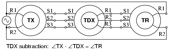
TDX subtraction.
The torque inputs in Figure above are TX and TDX. The torque output angular difference is TR.
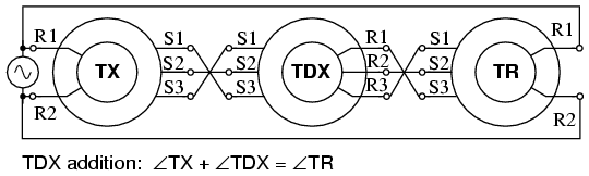
TDX Addition.
The torque inputs in Figure above are TX and TDX. The torque output angular sum is TR.
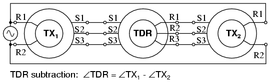
TDR subtraction.
The torque inputs in Figure above are TX1 and TX2. The torque output angular difference is TDR.
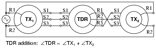
TDR addition.
The torque inputs in Figure above are TX1 and TX2. The torque output angular sum is TDR.
Control transformer
A variation of the synchro transmitter is the control transformer. It has three equally spaced stator windings like a TX. Its rotor is wound with more turns than a transmitter or receiver to make it more sensitive at detecting a null as it is rotated, typically, by a servo system. The CT (Control Transformer) rotor output is zero when it is oriented at a angle right angle to the stator magnetic field vector. Unlike a TX or RX, the CT neither transmits nor receives torque. It is simply a sensitive angular position detector.
Control transformer (CT) detects servo null.
In Figure above, the shaft of the TX is set to the desired position of the radar antenna. The servo system will cause the servo motor to drive the antenna to the commanded position. The CT compares the commanded to actual position and signals the servo amplifier to drive the motor until that commanded angle is achieved.
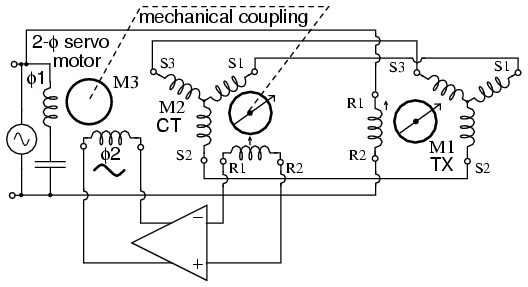
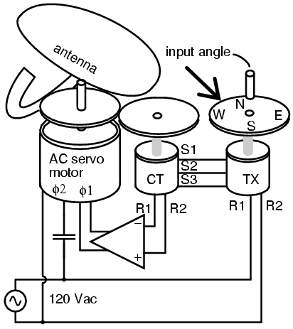
Servo uses CT to sense antenna position null
When the control transformer rotor detects a null at 90o to the axis of the stator field, there is no rotor output. Any rotor displacement produces an AC error voltage proportional to displacement. A servo (Figure above) seeks to minimize the error between a commanded and measured variable due to negative feedback. The control transformer compares the shaft angle to the the stator magnetic field angle, sent by the TX stator. When it measures a minimum, or null, the servo has driven the antenna and control transformer rotor to the commanded position. There is no error between measured and commanded position, no CT, control transformer, output to be amplified. The servo motor, a 2-phase motor, stops rotating. However, any CT detected error drives the amplifier which drives the motor until the error is minimized. This corresponds to the servo system having driven the antenna coupled CT to match the angle commanded by the TX.
The servo motor may drive a reduction gear train and be large compared to the TX and CT synchros. However, the poor efficiency of AC servo motors limits them to smaller loads. They are also difficult to control since they are constant speed devices. However, they can be controlled to some extent by varying the voltage to one phase with line voltage on the other phase. Heavy loads are more efficiently driven by large DC servo motors.
Airborne applications use 400Hz components– TX, CT, and servo motor. Size and weight of the AC magnetic components is inversely proportional to frequency. Therefore, use of 400 Hz components for aircraft applications, like moving control surfaces, saves size and weight.
Resolver
A resolver (Figure below) has two stator winding placed at 90o to each other, and a single rotor winding driven by alternating current. A resolver is used for polar to rectangular conversion. An angle input at the rotor shaft produces rectangular co-ordinates sinθ and cosθ proportional voltages on the stator windings.
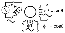
Resolver converts shaft angle to sine and cosine of angle.
For example, a black-box within a radar encodes the distance to a target as a sine wave proportional voltage V, with the bearing angle as a shaft angle. Convert to X and Y co-ordinates. The sine wave is fed to the rotor of a resolver. The bearing angle shaft is coupled to the resolver shaft. The coordinates (X, Y) are available on the resolver stator coils:
X=V(cos(∠bearing))
Y=V(sin(∠bearing))The Cartesian coordinates (X, Y) may be plotted on a map display.
A TX (torque transmitter) may be adapted for service as a resolver. (Figure below)
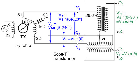
Scott-T converts 3-φ to 2-φ enabling TX to perform resolver function.
It is possible to derive resolver-like quadrature angular components from a synchro transmitter by using a Scott-T transformer. The three TX outputs, 3-phases, are processed by a Scott-T transformer into a pair of quadrature components. See Scott-T chapter 9 for details.
There is also a linear version of the resolver known as an inductosyn. The rotary version of the inductosyn has a finer resolution than a resolver.
Summary: Selsyn (synchro) motors
- A synchro, also known as a selsyn, is a rotary transformer used to transmit shaft torque.
- A TX, torque transmitter, accepts a torque input at its shaft for transmission on three-phase electrical outputs.
- An RX, torque receiver, accepts a three-phase electrical representation of an angular input for conversion to a torque output at its shaft. Thus, TX transmits a torque form an input shaft to a remote RX output shaft.
- A TDX, torque differential transmitter, sums an electrical angle input with a shaft angle input producing an electrical angle output
- A TDR, torque differential receiver, sums two electrical angle inputs producing a shaft angle output
- A CT, control transformer, detects a null when the rotor is positioned at a right angle to the stator angle input. A CT is typically a component of a servo– feedback system.
- A Resolver outputs a quadrature sinθ and cosine(theta) representation of the shaft angle input instead of a three-phase output.
- The three-phase output of a TX is converted to a resolver style output by a Scott-T transformer.