Input and output coupling
To overcome the challenge of creating necessary DC bias voltage for an amplifier's input signal without resorting to the insertion of a battery in series with the AC signal source, we used a voltage divider connected across the DC power source. To make this work in conjunction with an AC input signal, we "coupled" the signal source to the divider through a capacitor, which acted as a high-pass filter. With that filtering in place, the low impedance of the AC signal source couldn't "short out" the DC voltage dropped across the bottom resistor of the voltage divider. A simple solution, but not without any disadvantages.
Most obvious is the fact that using a high-pass filter capacitor to couple the signal source to the amplifier means that the amplifier can only amplify AC signals. A steady, DC voltage applied to the input would be blocked by the coupling capacitor just as much as the voltage divider bias voltage is blocked from the input source. Furthermore, since capacitive reactance is frequency-dependent, lower-frequency AC signals will not be amplified as much as higher-frequency signals. Non-sinusoidal signals will tend to be distorted, as the capacitor responds differently to each of the signal's constituent harmonics. An extreme example of this would be a low-frequency square-wave signal:
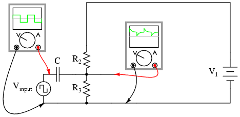
Incidentally, this same problem occurs when oscilloscope inputs are set to the "AC coupling" mode. In this mode, a coupling capacitor is inserted in series with the measured voltage signal to eliminate any vertical offset of the displayed waveform due to DC voltage combined with the signal. This works fine when the AC component of the measured signal is of a fairly high frequency, and the capacitor offers little impedance to the signal. However, if the signal is of a low frequency, and/or contains considerable levels of harmonics over a wide frequency range, the oscilloscope's display of the waveform will not be accurate.


In applications where the limitations of capacitive coupling would be intolerable, another solution may be used: direct coupling. Direct coupling avoids the use of capacitors or any other frequency-dependent coupling component in favor of resistors. A direct-coupled amplifier circuit might look something like this:
With no capacitor to filter the input signal, this form of coupling exhibits no frequency dependence. DC and AC signals alike will be amplified by the transistor with the same gain (the transistor itself may tend to amplify some frequencies better than others, but that is another subject entirely!).
If direct coupling works for DC as well as for AC signals, then why use capacitive coupling for any application? One reason might be to avoid any unwanted DC bias voltage naturally present in the signal to be amplified. Some AC signals may be superimposed on an uncontrolled DC voltage right from the source, and an uncontrolled DC voltage would make reliable transistor biasing impossible. The high-pass filtering offered by a coupling capacitor would work well here to avoid biasing problems.
Another reason to use capacitive coupling rather than direct is its relative lack of signal attenuation. Direct coupling through a resistor has the disadvantage of diminishing, or attenuating, the input signal so that only a fraction of it reaches the base of the transistor. In many applications, some attenuation is necessary anyway to prevent normal signal levels from "overdriving" the transistor into cutoff and saturation, so any attenuation inherent to the coupling network is useful anyway. However, some applications require that there be no signal loss from the input connection to the transistor's base for maximum voltage gain, and a direct coupling scheme with a voltage divider for bias simply won't suffice.
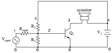
So far, we've discussed a couple of methods for coupling an input signal to an amplifier, but haven't addressed the issue of coupling an amplifier's output to a load. The example circuit used to illustrate input coupling will serve well to illustrate the issues involved with output coupling.
In our example circuit, the load is a speaker. Most speakers are electromagnetic in design: that is, they use the force generated by an lightweight electromagnet coil suspended within a strong permanent-magnet field to move a thin paper or plastic cone, producing vibrations in the air which our ears interpret as sound. An applied voltage of one polarity moves the cone outward, while a voltage of the opposite polarity will move the cone inward. To exploit cone's full freedom of motion, the speaker must receive true (unbiased) AC voltage. DC bias applied to the speaker coil tends to offset the cone from its natural center position, and this tends to limit the amount of back-and-forth motion it can sustain from the applied AC voltage without overtraveling. However, our example circuit applies a varying voltage of only one polarity across the speaker, because the speaker is connected in series with the transistor which can only conduct current one way. This situation would be unacceptable in the case of any high-power audio amplifier.
Somehow we need to isolate the speaker from the DC bias of the collector current so that it only receives AC voltage. One way to achieve this goal is to couple the transistor collector circuit to the speaker through a transformer:

Voltage induced in the secondary (speaker-side) of the transformer will be strictly due to variations in collector current, because the mutual inductance of a transformer only works on changes in winding current. In other words, only the AC portion of the collector current signal will be coupled to the secondary side for powering the speaker. The speaker will "see" true alternating current at its terminals, without any DC bias.
Transformer output coupling works, and has the added benefit of being able to provide impedance matching between the transistor circuit and the speaker coil with custom winding ratios. However, transformers tend to be large and heavy, especially for high-power applications. Also, it is difficult to engineer a transformer to handle signals over a wide range of frequencies, which is almost always required for audio applications. To make matters worse, DC current through the primary winding adds to the magnetization of the core in one polarity only, which tends to make the transformer core saturate more easily in one AC polarity cycle than the other. This problem is reminiscent of having the speaker directly connected in series with the transistor: a DC bias current tends to limit how much output signal amplitude the system can handle without distortion. Generally, though, a transformer can be designed to handle a lot more DC bias current than a speaker without running into trouble, so transformer coupling is still a viable solution in most cases.
Another method to isolate the speaker from DC bias in the output signal is to alter the circuit a bit and use a coupling capacitor in a manner similar to coupling the input signal to the amplifier:

This circuit resembles the more conventional form of common-emitter amplifier, with the transistor collector connected to the battery through a resistor. The capacitor acts as a high-pass filter, passing most of the AC voltage to the speaker while blocking all DC voltage. Again, the value of this coupling capacitor is chosen so that its impedance at the expected signal frequency will be arbitrarily low.
The blocking of DC voltage from an amplifier's output, be it via a transformer or a capacitor, is useful not only in coupling an amplifier to a load, but also in coupling one amplifier to another amplifier. "Staged" amplifiers are often used to achieve higher power gains than what would be possible using a single transistor:
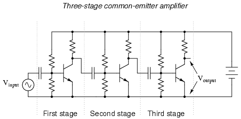
While it is possible to directly couple each stage to the next (via a resistor rather than a capacitor), this makes the whole amplifier very sensitive to variations in the DC bias voltage of the first stage, since that DC voltage will be amplified along with the AC signal until the last stage. In other words, the biasing of the first stage will affect the biasing of the second stage, and so on. However, if the stages are capacitively coupled as shown in the above illustration, the biasing of one stage has no effect on the biasing of the next, because DC voltage is blocked from passing on to the next stage.
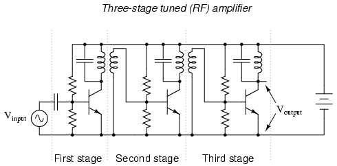
Transformer coupling between amplifier stages is also a possibility, but less often seen due to some of the problems inherent to transformers mentioned previously. One notable exception to this rule is in the case of radio-frequency amplifiers where coupling transformers are typically small, have air cores (making them immune to saturation effects), and can be made part of a resonant circuit so as to block unwanted harmonic frequencies from passing on to subsequent stages. The use of resonant circuits assumes that the signal frequency remains constant, of course, but this is typically the case in radio circuitry. Also, the "flywheel" effect of LC tank circuits allows for class C operation for high efficiency:
Having said all this, it must be mentioned that it is possible to use direct coupling within a multi-stage transistor amplifier circuit. In cases where the amplifier is expected to handle DC signals, this is the only alternative.
- REVIEW:
- Capacitive coupling acts like a high-pass filter on the input of an amplifier. This tends to make the amplifier's voltage gain decrease at lower signal frequencies. Capacitive-coupled amplifiers are all but unresponsive to DC input signals.
- Direct coupling with a series resistor instead of a series capacitor avoids the problem of frequency-dependent gain, but has the disadvantage of reducing amplifier gain for all signal frequencies by attenuating the input signal.
- Transformers and capacitors may be used to couple the output of an amplifier to a load, to eliminate DC voltage from getting to the load.
- Multi-stage amplifiers often make use of capacitive coupling between stages to eliminate problems with the bias from one stage affecting the bias of another.