Multiple-input gates
Inverters and buffers exhaust the possibilities for single-input gate circuits. What more can be done with a single logic signal but to buffer it or invert it? To explore more logic gate possibilities, we must add more input terminals to the circuit(s).
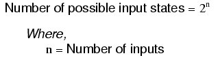
Adding more input terminals to a logic gate increases the number of input state possibilities. With a single-input gate such as the inverter or buffer, there can only be two possible input states: either the input is "high" (1) or it is "low" (0). As was mentioned previously in this chapter, a two input gate has four possibilities (00, 01, 10, and 11). A three-input gate has eight possibilities (000, 001, 010, 011, 100, 101, 110, and 111) for input states. The number of possible input states is equal to two to the power of the number of inputs:
This increase in the number of possible input states obviously allows for more complex gate behavior. Now, instead of merely inverting or amplifying (buffering) a single "high" or "low" logic level, the output of the gate will be determined by whatever combination of 1's and 0's is present at the input terminals.
Since so many combinations are possible with just a few input terminals, there are many different types of multiple-input gates, unlike single-input gates which can only be inverters or buffers. Each basic gate type will be presented in this section, showing its standard symbol, truth table, and practical operation. The actual TTL circuitry of these different gates will be explored in subsequent sections.
The AND gate
One of the easiest multiple-input gates to understand is the AND gate, so-called because the output of this gate will be "high" (1) if and only if all inputs (first input and the second input and . . .) are "high" (1). If any input(s) are "low" (0), the output is guaranteed to be in a "low" state as well.
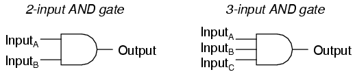
In case you might have been wondering, AND gates are made with more than three inputs, but this is less common than the simple two-input variety.
A two-input AND gate's truth table looks like this:
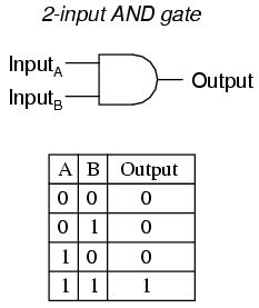
What this truth table means in practical terms is shown in the following sequence of illustrations, with the 2-input AND gate subjected to all possibilities of input logic levels. An LED (Light-Emitting Diode) provides visual indication of the output logic level:
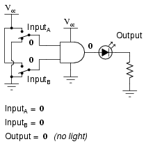
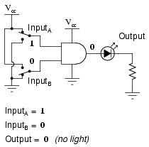
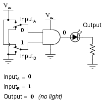

It is only with all inputs raised to "high" logic levels that the AND gate's output goes "high," thus energizing the LED for only one out of the four input combination states.
The NAND gate
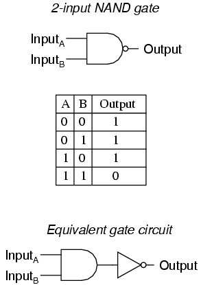
A variation on the idea of the AND gate is called the NAND gate. The word "NAND" is a verbal contraction of the words NOT and AND. Essentially, a NAND gate behaves the same as an AND gate with a NOT (inverter) gate connected to the output terminal. To symbolize this output signal inversion, the NAND gate symbol has a bubble on the output line. The truth table for a NAND gate is as one might expect, exactly opposite as that of an AND gate:
As with AND gates, NAND gates are made with more than two inputs. In such cases, the same general principle applies: the output will be "low" (0) if and only if all inputs are "high" (1). If any input is "low" (0), the output will go "high" (1).
The OR gate
Our next gate to investigate is the OR gate, so-called because the output of this gate will be "high" (1) if any of the inputs (first input or the second input or . . .) are "high" (1). The output of an OR gate goes "low" (0) if and only if all inputs are "low" (0).
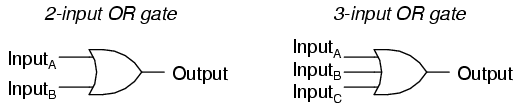
A two-input OR gate's truth table looks like this:
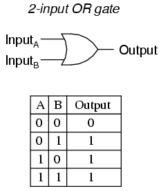
The following sequence of illustrations demonstrates the OR gate's function, with the 2-inputs experiencing all possible logic levels. An LED (Light-Emitting Diode) provides visual indication of the gate's output logic level:
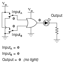

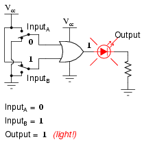
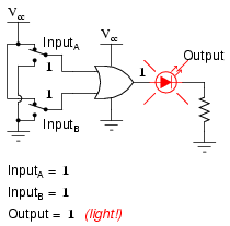
A condition of any input being raised to a "high" logic level makes the OR gate's output go "high," thus energizing the LED for three out of the four input combination states.
The NOR gate
As you might have suspected, the NOR gate is an OR gate with its output inverted, just like a NAND gate is an AND gate with an inverted output.
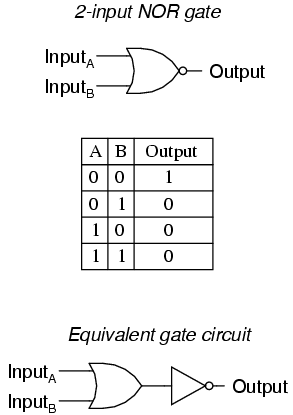
NOR gates, like all the other multiple-input gates seen thus far, can be manufactured with more than two inputs. Still, the same logical principle applies: the output goes "low" (0) if any of the inputs are made "high" (1). The output is "high" (1) only when all inputs are "low" (0).
The Negative-AND gate
A Negative-AND gate functions the same as an AND gate with all its inputs inverted (connected through NOT gates). In keeping with standard gate symbol convention, these inverted inputs are signified by bubbles. Contrary to most peoples' first instinct, the logical behavior of a Negative-AND gate is not the same as a NAND gate. Its truth table, actually, is identical to a NOR gate:

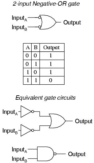
The Negative-OR gate
Following the same pattern, a Negative-OR gate functions the same as an OR gate with all its inputs inverted. In keeping with standard gate symbol convention, these inverted inputs are signified by bubbles. The behavior and truth table of a Negative-OR gate is the same as for a NAND gate:
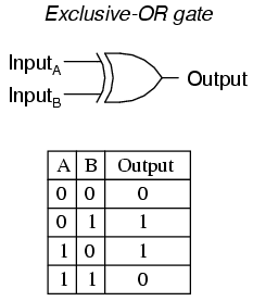
The Exclusive-OR gate
The last six gate types are all fairly direct variations on three basic functions: AND, OR, and NOT. The Exclusive-OR gate, however, is something quite different.
Exclusive-OR gates output a "high" (1) logic level if the inputs are at different logic levels, either 0 and 1 or 1 and 0. Conversely, they output a "low" (0) logic level if the inputs are at the same logic levels. The Exclusive-OR (sometimes called XOR) gate has both a symbol and a truth table pattern that is unique:
There are equivalent circuits for an Exclusive-OR gate made up of AND, OR, and NOT gates, just as there were for NAND, NOR, and the negative-input gates. A rather direct approach to simulating an Exclusive-OR gate is to start with a regular OR gate, then add additional gates to inhibit the output from going "high" (1) when both inputs are "high" (1):
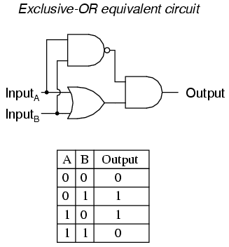
In this circuit, the final AND gate acts as a buffer for the output of the OR gate whenever the NAND gate's output is high, which it is for the first three input state combinations (00, 01, and 10). However, when both inputs are "high" (1), the NAND gate outputs a "low" (0) logic level, which forces the final AND gate to produce a "low" (0) output.
Another equivalent circuit for the Exclusive-OR gate uses a strategy of two AND gates with inverters, set up to generate "high" (1) outputs for input conditions 01 and 10. A final OR gate then allows either of the AND gates' "high" outputs to create a final "high" output:
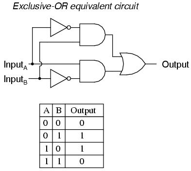
Exclusive-OR gates are very useful for circuits where two or more binary numbers are to be compared bit-for-bit, and also for error detection (parity check) and code conversion (binary to Grey and vice versa).
The Exclusive-NOR gate
Finally, our last gate for analysis is the Exclusive-NOR gate, otherwise known as the XNOR gate. It is equivalent to an Exclusive-OR gate with an inverted output. The truth table for this gate is exactly opposite as for the Exclusive-OR gate:
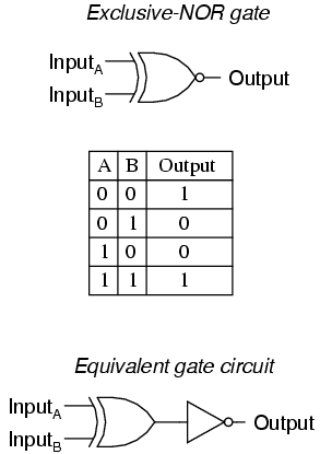
As indicated by the truth table, the purpose of an Exclusive-NOR gate is to output a "high" (1) logic level whenever both inputs are at the same logic levels (either 00 or 11).
- REVIEW:
- Rule for an AND gate: output is "high" only if first input and second input are both "high."
- Rule for an OR gate: output is "high" if input A or input B are "high."
- Rule for a NAND gate: output is not "high" if both the first input and the second input are "high."
- Rule for a NOR gate: output is not "high" if either the first input or the second input are "high."
- A Negative-AND gate behaves like a NOR gate.
- A Negative-OR gate behaves like a NAND gate.
- Rule for an Exclusive-OR gate: output is "high" if the input logic levels are different.
- Rule for an Exclusive-NOR gate: output is "high" if the input logic levels are the same.