Current divider
PARTS AND MATERIALS
- Calculator (or pencil and paper for doing arithmetic)
- 6-volt battery
- Assortment of resistors between 1 KΩ and 100 kΩ in value
CROSS-REFERENCES
Lessons In Electric Circuits, Volume 1, chapter 6: "Divider Circuits and Kirchhoff's Laws"
LEARNING OBJECTIVES
- Voltmeter use
- Ammeter use
- Ohmmeter use
- Use of Ohm's Law
- Use of Kirchhoff's Current Law (KCL)
- Current divider design
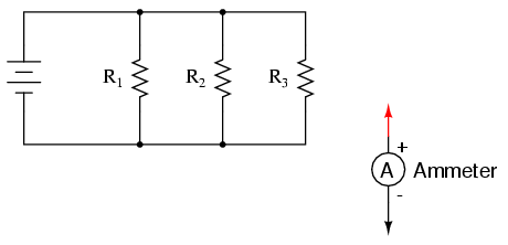
SCHEMATIC DIAGRAM
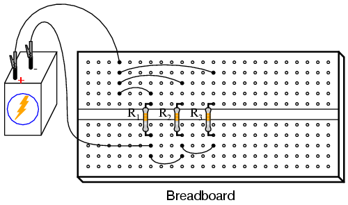
ILLUSTRATION
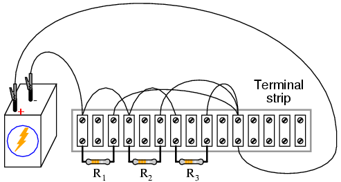
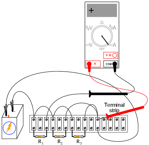
Normally, it is considered improper to secure more than two wires under a single terminal strip screw. In this illustration, I show three wires joining at the top screw of the rightmost lug used on this strip. This is done for the ease of proving a concept (of current summing at a circuit node), and does not represent professional assembly technique.
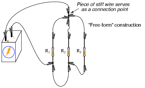
The non-professional nature of the "free-form" construction method merits no further comment.
INSTRUCTIONS
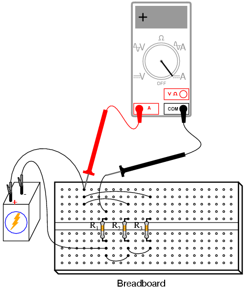
Once again, I show different methods of constructing the same circuit: breadboard, terminal strip, and "free-form." Experiment with all these construction formats and become familiar with their respective advantages and disadvantages.
Select three resistors from your resistor assortment and measure the resistance of each one with an ohmmeter. Note these resistance values with pen and paper, for reference in your circuit calculations.
Connect the three resistors in parallel to and each other, and with the 6-volt battery, as shown in the illustrations. Measure battery voltage with a voltmeter after the resistors have been connected to it, noting this voltage figure on paper as well. It is advisable to measure battery voltage while it's powering the resistor circuit because this voltage may differ slightly from a no-load condition.
Measure voltage across each of the three resistors. What do you notice? In a series circuit, current is equal through all components at any given time. In a parallel circuit, voltage is the common variable between all components.
Use Ohm's Law (I=E/R) to calculate current through each resistor, then verify this calculated value by measuring current with a digital ammeter. Place the red probe of the ammeter at the point where the positive (+) ends of the resistors connect to each other and lift one resistor wire at a time, connecting the meter's black probe to the lifted wire. In this manner, measure each resistor current, noting both the magnitude of the current and the polarity. In these illustrations, I show an ammeter used to measure the current through R1:
Measure current for each of the three resistors, comparing with the current figures calculated previously. With the digital ammeter connected as shown, all three indications should be positive, not negative.
Now, measure total circuit current, keeping the ammeter's red probe on the same point of the circuit, but disconnecting the wire leading to the positive (+) side of the battery and touching the black probe to it:
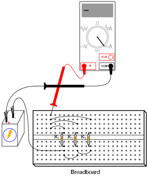
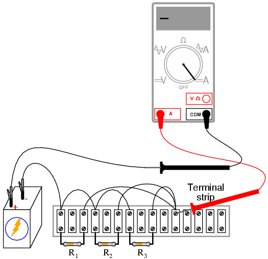
Note both the magnitude and the sign of the current as indicated by the ammeter. Add this figure (algebraically) to the three resistor currents. What do you notice about the result that is similar to the Kirchhoff's Voltage Law experiment? Kirchhoff's Current Law is to currents "summing" at a point (node) in a circuit, just as Kirchhoff's Voltage Law is to voltages adding in a series loop: in both cases, the algebraic sum is equal to zero.
This Law is also very useful in the mathematical analysis of circuits. Along with Kirchhoff's Voltage Law, it allows us to generate equations describing several variables in a circuit, which may then be solved using a variety of mathematical techniques.
Now consider the four current measurements as all positive numbers: the first three representing the current through each resistor, and the fourth representing total circuit current as a positive sum of the three "branch" currents. Each resistor (branch) current is a fraction, or percentage, of the total current. This is why a parallel resistor circuit is often called a current divider.
Disconnect the battery from the rest of the circuit, and measure resistance across the parallel resistors. You may read total resistance across any of the individual resistors' terminals and obtain the same indication: it will be a value less than any of the individual resistor values. This is often surprising to new students of electricity, that you read the exact same (total) resistance figure when connecting an ohmmeter across any one of a set of parallel-connected resistors. It makes sense, though, if you consider the points in a parallel circuit in terms of electrical commonality. All parallel components are connected between two sets of electrically common points. Since the meter cannot distinguish between points common to each other by way of direct connection, to read resistance across one resistor is to read the resistance of them all. The same is true for voltage, which is why battery voltage could be read across any one of the resistors as easily as it could be read across the battery terminals directly.
If you divide the battery voltage (previously measured) by this total resistance figure, you should obtain a figure for total current (I=E/R) closely matching the measured figure.
The ratio of resistor current to total current is the same as the ratio of total resistance to individual resistance. For example, if a 10 kΩ resistor is part of a current divider circuit with a total resistance of 1 kΩ, that resistor will conduct 1/10 of the total current, whatever value that current total happens to be.
COMPUTER SIMULATION
Schematic with SPICE node numbers:
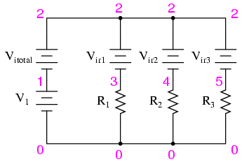
Ammeters in SPICE simulations are actually zero-voltage sources inserted in the paths of electron flow. You will notice the voltage sources Vir1, Vir2, and Vir3 are set to 0 volts in the netlist. When electrons enter the negative side of one of these "dummy" batteries and out the positive, the battery's current indication will be a positive number. In other words, these 0-volt sources are to be regarded as ammeters with the red probe on the long-line side of the battery symbol and the black probe on the short-line side.
Netlist (make a text file containing the following text, verbatim):
Current divider
v1 1 0
r1 3 0 2k
r2 4 0 3k
r3 5 0 5k
vitotal 2 1 dc 0
vir1 2 3 dc 0
vir2 2 4 dc 0
vir3 2 5 dc 0
.dc v1 6 6 1
.print dc i(vitotal) i(vir1) i(vir2) i(vir3)
.end
When run, SPICE will print a line of text containing four current figures, the first current representing the total as a negative quantity, and the other three representing currents for resistors R1, R2, and R3. When algebraically added, the one negative figure and the three positive figures will form a sum of zero, as described by Kirchhoff's Current Law.