AC network analysis
Question 1:
|
Don't just sit there! Build something!! |
Learning to mathematically analyze circuits requires much study and practice. Typically, students practice by working through lots of sample problems and checking their answers against those provided by the textbook or the instructor. While this is good, there is a much better way.
You will learn much more by actually
building and analyzing real circuits, letting your test equipment provide the änswers" instead of a book or another person. For successful circuit-building exercises, follow these steps:
-
1.
-
Carefully measure and record all component values prior to circuit construction.
-
2.
- Draw the schematic diagram for the circuit to be analyzed.
-
3.
- Carefully build this circuit on a breadboard or other convenient medium.
-
4.
- Check the accuracy of the circuit's construction, following each wire to each connection point, and verifying these elements one-by-one on the diagram.
-
5.
- Mathematically analyze the circuit, solving for all voltage and current values.
-
6.
- Carefully measure all voltages and currents, to verify the accuracy of your analysis.
-
7.
- If there are any substantial errors (greater than a few percent), carefully check your circuit's construction against the diagram, then carefully re-calculate the values and re-measure.
For AC circuits where inductive and capacitive reactances (impedances) are a significant element in the calculations, I recommend high quality (high-Q) inductors and capacitors, and powering your circuit with low frequency voltage (power-line frequency works well) to minimize parasitic effects. If you are on a restricted budget, I have found that inexpensive electronic musical keyboards serve well as "function generators" for producing a wide range of audio-frequency AC signals. Be sure to choose a keyboard "voice" that closely mimics a sine wave (the "panflute" voice is typically good), if sinusoidal waveforms are an important assumption in your calculations.
As usual, avoid very high and very low resistor values, to avoid measurement errors caused by meter "loading". I recommend resistor values between 1 k
W and 100 k
W.
One way you can save time and reduce the possibility of error is to begin with a very simple circuit and incrementally add components to increase its complexity after each analysis, rather than building a whole new circuit for each practice problem. Another time-saving technique is to re-use the same components in a variety of different circuit configurations. This way, you won't have to measure any component's value more than once.
Reveal Answer
Let the electrons themselves give you the answers to your own "practice problems"!
Notes:
It has been my experience that students require much practice with circuit analysis to become proficient. To this end, instructors usually provide their students with lots of practice problems to work through, and provide answers for students to check their work against. While this approach makes students proficient in circuit theory, it fails to fully educate them.
Students don't just need mathematical practice. They also need real, hands-on practice building circuits and using test equipment. So, I suggest the following alternative approach: students should build their own "practice problems" with real components, and try to mathematically predict the various voltage and current values. This way, the mathematical theory "comes alive," and students gain practical proficiency they wouldn't gain merely by solving equations.
Another reason for following this method of practice is to teach students scientific method: the process of testing a hypothesis (in this case, mathematical predictions) by performing a real experiment. Students will also develop real troubleshooting skills as they occasionally make circuit construction errors.
Spend a few moments of time with your class to review some of the "rules" for building circuits before they begin. Discuss these issues with your students in the same Socratic manner you would normally discuss the worksheet questions, rather than simply telling them what they should and should not do. I never cease to be amazed at how poorly students grasp instructions when presented in a typical lecture (instructor monologue) format!
An excellent way to introduce students to the mathematical analysis of real circuits is to have them first determine component values (L and C) from measurements of AC voltage and current. The simplest circuit, of course, is a single component connected to a power source! Not only will this teach students how to set up AC circuits properly and safely, but it will also teach them how to measure capacitance and inductance without specialized test equipment.
A note on reactive components: use high-quality capacitors and inductors, and try to use low frequencies for the power supply. Small step-down power transformers work well for inductors (at least two inductors in one package!), so long as the voltage applied to any transformer winding is less than that transformer's rated voltage for that winding (in order to avoid saturation of the core).
A note to those instructors who may complain about the "wasted" time required to have students build real circuits instead of just mathematically analyzing theoretical circuits:
What is the purpose of students taking your course?
If your students will be working with real circuits, then they should learn on real circuits whenever possible. If your goal is to educate theoretical physicists, then stick with abstract analysis, by all means! But most of us plan for our students to do something in the real world with the education we give them. The "wasted" time spent building real circuits will pay huge dividends when it comes time for them to apply their knowledge to practical problems.
Furthermore, having students build their own practice problems teaches them how to perform primary research, thus empowering them to continue their electrical/electronics education autonomously.
In most sciences, realistic experiments are much more difficult and expensive to set up than electrical circuits. Nuclear physics, biology, geology, and chemistry professors would just love to be able to have their students apply advanced mathematics to real experiments posing no safety hazard and costing less than a textbook. They can't, but you can. Exploit the convenience inherent to your science, and get those students of yours practicing their math on lots of real circuits!
Hide Answer
Question 2:
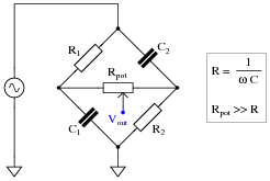
This phase-shifting bridge circuit is supposed to provide an output voltage with a variable phase shift from -45
o (lagging) to +45
o (leading), depending on the position of the potentiometer wiper:
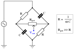
Suppose, though, that the output signal is stuck at -45
o lagging the source voltage, no matter where the potentiometer is set. Identify a likely failure that could cause this to happen, and explain why this failure could account for the circuit's strange behavior.
Reveal Answer
A broken connection between the right-hand terminal of the potentiometer and the bridge could cause this to happen:
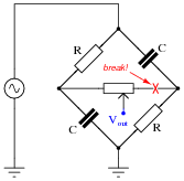
I'll let you figure out why!
Notes:
It is essential, of course, that students understand the operational principle of this circuit before they may even attempt to diagnose possible faults. You may find it necessary to discuss this circuit in detail with your students before they are ready to troubleshoot it.
In case anyone asks, the symbolism Rpot >> R means "potentiometer resistance is much greater than the fixed resistance value."
Hide Answer
Question 3:
Complex number arithmetic makes possible the analysis of AC circuits using (almost) the exact same Laws that were learned for DC circuit analysis. The only bad part about this is that doing complex-number arithmetic by hand can be very tedious. Some calculators, though, are able to add, subtract, multiply, divide, and invert complex quantities as easy as they do scalar quantities, making this method of AC circuit analysis relatively easy.
This question is really a series of practice problems in complex number arithmetic, the purpose being to give you lots of practice using the complex number facilities of your calculator (or to give you a
lot of practice doing trigonometry calculations, if your calculator does not have the ability to manipulate complex numbers!).
Addition and subtraction:
|
(5 + j6) + (2 - j1) =
|
(10 - j8) + (4 - j3) =
|
(-3 + j0) + (9 - j12) =
|
|
(3 + j5) - (0 - j9) =
|
(25 - j84) - (4 - j3) =
|
(-1500 + j40) + (299 - j128) =
|
|
(25 �15o) + (10 �74o) =
|
(1000 �43o) + (1200 �-20o) =
|
(522 �71o) - (85 �30o) =
|
Multiplication and division:
|
(25 �15o) ×(12 �10o) =
|
(1 �25o) ×(500 �-30o) =
|
(522 �71o) ×(33 �9o) =
|
|
[(10 �-80o)/(1 �0o)] =
|
[(25 �120o)/(3.5 �-55o)] =
|
[(-66 �67o)/(8 �-42o)] =
|
|
(3 + j5) ×(2 - j1) =
|
(10 - j8) ×(4 - j3) =
|
[((3 + j4))/((12 - j2))] =
|
Reciprocation:
|
[1/((15 �60o))] =
|
[1/((750 �-38o))] =
|
[1/((10 + j3))] =
|
|
[1/([1/(15 �45o)] + [1/(92 �-25o)])] =
|
[1/([1/(1200 �73o)] + [1/(574 �21o)])] =
|
[1/([1/(23k �-67o)] + [1/(10k �-81o)])] =
|
|
[1/([1/(110 �-34o)] + [1/(80 �19o)] + [1/(70 �10)])] =
|
[1/([1/(89k �-5o)] + [1/(15k �33o)] + [1/(9.35k �45)])] =
|
[1/([1/(512 �34o)] + [1/(1k �-25o)] + [1/(942 �-20)] + [1/(2.2k �44o)])] =
|
Reveal Answer
Addition and subtraction:
|
(5 + j6) + (2 - j1) =
|
(10 - j8) + (4 - j3) =
|
(-3 + j0) + (9 - j12) =
|
|
(3 + j5) - (0 - j9) =
|
(25 - j84) - (4 - j3) =
|
(-1500 + j40) + (299 - j128) =
|
|
3 + j14 |
21 - j81 |
-1201 - j88 |
|
(25 �15o) + (10 �74o) =
|
(1000 �43o) + (1200 �-20o) =
|
(522 �71o) - (85 �30o) =
|
|
31.35 �30.87o |
1878.7 �8.311o |
461.23 �77.94o |
Multiplication and division:
|
(25 �15o) ×(12 �10o) =
|
(1 �25o) ×(500 �-30o) =
|
(522 �71o) ×(33 �9o) =
|
|
300 �25o |
500 �-5o |
17226 �80o |
|
[(10 �-80o)/(1 �0o)] =
|
[(25 �120o)/(3.5 �-55o)] =
|
[(-66 �67o)/(8 �-42o)] =
|
|
10 �-80o |
7.142 �175o |
8.25 �-71o |
|
(3 + j5) ×(2 - j1) =
|
(10 - j8) ×(4 - j3) =
|
[((3 + j4))/((12 - j2))] =
|
|
11 + j7 |
16 - j62 |
0.1892 + j0.3649 |
Reciprocation:
|
[1/((15 �60o))] =
|
[1/((750 �-38o))] =
|
[1/((10 + j3))] =
|
|
0.667 �-60o |
0.00133 �38o |
0.0917 -j0.0275 |
|
[1/([1/(15 �45o)] + [1/(92 �-25o)])] =
|
[1/([1/(1200 �73o)] + [1/(574 �21o)])] =
|
[1/([1/(23k �-67o)] + [1/(10k �-81o)])] =
|
|
14.06 �36.74o |
425.7 �37.23o |
7.013k �-76.77o |
|
[1/([1/(110 �-34o)] + [1/(80 �19o)] + [1/(70 �10)])] =
|
[1/([1/(89k �-5o)] + [1/(15k �33o)] + [1/(9.35k �45)])] =
|
[1/([1/(512 �34o)] + [1/(1k �-25o)] + [1/(942 �-20)] + [1/(2.2k �44o)])] =
|
|
29.89 �2.513o |
5.531k �37.86o |
256.4 �9.181o |
Notes:
I suggest you let your students discover how to use the complex number facilities of their scientific calculators on their own. My experience has been that students both young and old take to this challenge readily, because they realize learning how to use their calculators will save them a tremendous amount of hand calculations!
Hide Answer
Question 4:
Is it safe to close the breaker between these two alternators if their output frequencies are different? Explain why or why not.

Reveal Answer
When the frequencies of two or more AC voltage sources are different, the phase shift(s) between them are constantly changing.
Follow-up question: what must be done to make the two alternators' frequencies equal to each other?
Notes:
Ask your students to calculate how fast the voltages from these two alternators "roll" in and out of phase with each other.
Hide Answer
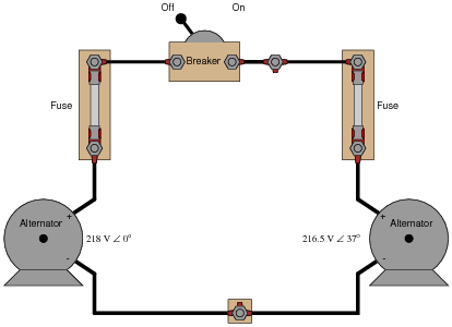
Question 5:
Given the output voltages of the two alternators, it is
not safe to close the breaker. Explain why.
Reveal Answer
The greatest problem with closing the breaker is the 37
o phase shift between the two alternators' output voltages.
Follow-up question: what must be done to bring the two alternator voltages into phase with each other?
Challenge question: once the breaker is closed, can the two alternators ever fall out of phase with each other again?
Notes:
Discuss the consequences of closing the breaker when there is such a large phase shift between the two alternator output voltages. What will likely happen in the circuit if the breaker is closed under these conditions?
Ask your students whether or not the discrepancy in output voltage (218 VAC versus 216.5 VAC) is of any consequence in closing the breaker. Why is phase shift the only factor mentioned in the answer as a reason not to close the breaker?
This question serves to illustrate alternator theory as well as AC network analysis principles. The "phase-locking" phenomenon of two paralleled alternators is very important for students to understand if they are to do any work related to AC power generation systems.
Hide Answer
Question 6:
A remote speaker for an audio system is connected to the amplifier by means of a long, 2-conductor cable:
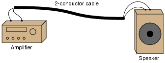
This system may be schematically modeled as an AC voltage source connected to a load resistor:

Suppose we decided to use the 2-conductor cable for more than just conveying an audio (AC) signal - we want to use it to carry DC power as well to energize a small lamp. However, if we were to simply connect the DC power source in parallel with the amplifier output at one end, and the lamp in parallel with the speaker at the other, bad things would happen:
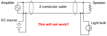
If we were to connect the components together as shown above, the DC power source will likely damage the amplifier by being directly connected to it, the speaker will
definitely be damaged by the application of significant DC voltage to its coil, and the light bulb will waste audio power by acting as a second (non-audible) load. Suffice to say, this is a bad idea.
Using inductors and capacitors as "filtering" components, though, we can make this system work:
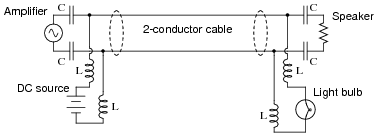
Apply the Superposition Theorem to this circuit to demonstrate that the audio and DC signals will not interfere with each other as they would if directly connected. Assume that the capacitors are of such large value that they present negligible impedance to the audio signal (Z
C � 0
W) and that the inductors are sufficiently large that they present infinite impedance to the audio signal (Z
L � �).
Reveal Answer
As each source is considered separately, the reactive components ensure each load receives the correct source voltage, with no interference.
Notes:
Such "power-plus-data" strategies are made possible by the Superposition Theorem and the linearity of resistors, capacitors, and inductors. If time permits, this would be a good opportunity to discuss "power-line carrier" systems, where high-frequency data is transmitted over power line conductors. The venerable X10 network system is an example for residential power wiring, while power distribution utilities have been using this "PLC" technology (the acronym not to be confused with Programmable Logic Controllers) for decades over high-voltage transmission lines.
Hide Answer
Question 7:
Explain why this bridge circuit can
never achieve balance:
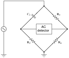
Reveal Answer
Even though impedance magnitudes may be balanced, the phase angles cannot.
Follow-up question: explain why it would
not work to use an oscilloscope as the "detector" in this bridge circuit:
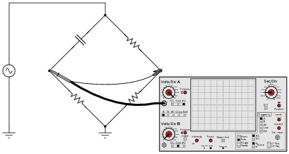
Hint: beware of
ground connections!
Challenge question: explain how you
could use this same oscilloscope as the detector in this bridge circuit without changing the ground location at the lower terminal of the AC source.
Notes:
Explain to your students that AC bridges, while fundamentally the same as DC bridges, do have their differences. Their knowledge of AC circuit calculations (with complex numbers) should be enough for them to see why this is so.
Hide Answer
Question 8:
Calculate the impedance value necessary to balance this AC bridge, expressing your answer in both polar and rectangular forms:
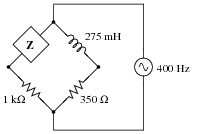
Reveal Answer
Z = 1.975 k
W � 90
o (polar form)
Z = 0 + j1.975 k
W (rectangular form)
Follow-up question: what type and size of component will provide this exact amount of impedance at 400 Hz?
Notes:
So long as complex quantities are used, AC bridge circuits "balance" just the same way that DC bridge circuits balance. Consequently, this is really nothing new for your students if they've already studied DC Wheatstone bridge circuits.
Hide Answer
Question 9:
Calculate the impedance value necessary to balance this AC bridge, expressing your answer in both polar and rectangular forms:
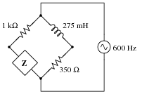
Also, describe what sort of device might be appropriate to serve as a "null detector" to indicate when bridge balance has been achieved, and where this device would be connected to in the bridge circuit.
Reveal Answer
Z = 337.6
W � -90
o (polar form)
Z = 0 - j337.6
W (rectangular form)
The simplest "null detector" for this type of AC bridge would be a sensitive pair of audio headphones, as 600 Hz is well within the audio range, and would be heard as a tone in the headphones.
Follow-up question: what type and size of component will provide this exact amount of impedance at 600 Hz?
Notes:
So long as complex quantities are used, AC bridge circuits "balance" just the same way that DC bridge circuits balance. Consequently, this is really nothing new for your students if they've already studied DC Wheatstone bridge circuits.
Hide Answer
Question 10:
An AC bridge circuit commonly used to make precision measurements of inductors is the
Maxwell-Wien bridge. It uses a combination of standard resistors and capacitors to "balance out" the inductor of unknown value in the opposite arm of the bridge:
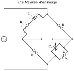
Suppose this bridge circuit balances when C
s is adjusted to 120 nF and R
s is adjusted to 14.25 k
W. If the source frequency is 400 Hz, and the two fixed-value resistors are 1 k
W each, calculate the inductance (L
x) and resistance (R
x) of the inductor being tested.
Reveal Answer
L
x = 120 mH
R
x = 70.175
W
Notes:
There is actually a way to solve for the values of Lx and Rx in a Maxwell-Wien bridge circuit without using complex numbers at all. If one or more of your students find out how to do so through their research, don't consider it "cheating." Rather, applaud their research, because they found a quicker path to a solution.
This, of course, doesn't mean you don't ask them to work through the problem using complex numbers! The benefit of students researching other means of solution simply provides more alternative solution strategies to the same problem, which is a very good thing.
Hide Answer
Question 11:
Electrical engineers often represent impedances in rectangular form for the sake of algebraic manipulation: to be able to construct and manipulate equations involving impedance, in terms of the components' fundamental values (resistors in ohms, capacitors in farads, and inductors in henrys).
For example, the impedance of a series-connected resistor (R) and inductor (L) would be represented as follows, with angular velocity (
w) being equal to 2
pf:
Using the same algebraic notation, represent each of the following complex quantities:
-
�
-
Impedance of a single capacitor (C) =
-
�
- Impedance of a series resistor-capacitor (R, C) network =
-
�
- Admittance of a parallel inductor-resistor (L, R) network =
-
�
- Admittance of a parallel resistor-capacitor (R, C) network =
Reveal Answer
-
�
-
Impedance of a single capacitor (C) = -j [1/(wC)]
-
�
- Impedance of a series resistor-capacitor (R, C) network = R -j [1/(wC)]
-
�
- Admittance of a parallel inductor-resistor (L, R) network = 1/R -j [1/(wL)]
-
�
- Admittance of a parallel resistor-capacitor (R, C) network = 1/R +j wC
Notes:
One possible point of confusion here is the sign of j after inversion. If it is not evident from the answers, 1/j is equal to -j, so that the impedance of an inductor (j wL) becomes -j [1/(wL)] when converted into an admittance.
Hide Answer
Question 12:
Mathematical analysis of the Maxwell-Wien bridge is as follows:

|
Zx = Rx + jwLx Impedance of unknown inductance/resistance arm |
|
|
Zs =
|
1
|
Impedance of standard capacitance/resistance arm |
|
|
Ys =
|
1
Rs
|
+ jwCs Admittance of standard capacitance/resistance arm |
|
|
|
Zx
ZR
|
=
|
ZR
Zs
|
or
|
Zx
ZR
|
= ZRYs Bridge balance equation |
|
|
Rx + jwLx = R2 |
�
�
|
1
Rs
|
+ jwCs |
�
�
|
|
|
|
Rx + jwLx =
|
R2
Rs
|
+ jwR2 Cs |
|
|
Separating real and imaginary terms . . . |
|
|
jwLx = jwR2 Cs (Imaginary) |
|
Note that neither of the two equations solving for unknown quantities (R
x = [(R
2)/(R
s)] and L
x = R
2 C
s) contain the variable
w. What does this indicate about the Maxwell-Wien bridge?
Reveal Answer
This means the source frequency is irrelevant to bridge balance.
Notes:
A rule that students will need to be aware of in order to follow all the algebra shown here is 1/j = -j. A brief proof is given here:
Otherwise, the admittance equation (
Ys = [1/(R
s)] + j
wC
s) will not make sense.
One type of AC bridge is called a
noise bridge, using a "noise" (broadly mixed frequencies) source as the excitation voltage. Discuss with your students how the Maxwell-Wien bridge would be a suitable topology for use with a noise source, whereas other bridge topologies might not.
Hide Answer
Question 13:
Suppose we have two equivalent LR networks, one series and one parallel, such that they have the exact same total impedance (
Ztotal):
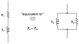
We may write an equation for the impedance of each network in rectangular form, like this:
|
Zs = Rs + jXs (series network) |
|
|
Zp =
|
1
|
(parallel network) |
|
Since we are told these two networks are equivalent to one another, with equal impedances, these two expressions in rectangular form must also be equal to each other:
Algebraically reduce this equation to its simplest form, showing how R
s, R
p, X
s, and X
p relate.
Challenge question: combine the result of that simplification with the equations solving for
scalar impedance of series and parallel networks (Z
s2 = R
s2 + X
s2 for series and Z
p2 = [1/([1/(R
p2)] + [1/(X
p2)])] for parallel) to prove the following transformative equations, highly useful for "translating" a series network into a parallel network and visa-versa:
Reveal Answer
Due to the complexity of the algebra, I will show the complete solution here:
|
(Rs + jXs)
|
�
�
|
1
Rp
|
- j
|
1
Xp
|
�
�
|
= 1
|
|
|
|
Rs
Rp
|
- j
|
Rs
Xp
|
+ j
|
Xs
Rp
|
-j2 |
Xs
Xp
|
= 1
|
|
|
|
Rs
Rp
|
- j
|
Rs
Xp
|
+ j
|
Xs
Rp
|
+
|
Xs
Xp
|
= 1
|
|
|
|
Rs
Rp
|
+
|
Xs
Xp
|
+ j
|
�
�
|
Xs
Rp
|
- |
Rs
Xp
|
�
�
|
= 1
|
|
|
Separating real and imaginary terms . . . |
|
|
j
|
�
�
|
Xs
Rp
|
- |
Rs
Xp
|
�
�
|
= j0 (Imaginary) |
|
|
Just working with the imaginary equation now . . . |
|
|
j
|
�
�
|
Xs
Rp
|
- |
Rs
Xp
|
�
�
|
= j0
|
|
In answer to the challenge question, where we now introduce scalar relationships for series and parallel networks:
|
Zs2 = Rs2 + Xs2 Series impedance |
|
|
Zp2 =
|
1
|
Parallel impedance |
|
|
Solving each scalar impedance equation for reactance X . . . |
|
|
Preparing the original solution for subsitution . . . |
|
|
Subsituting these definitions for reactance into this prepared equation . . . |
|
|
|
�
�
�
|
1
|
�
�
�
|
(Zs2 - Rs2) = Rp2 Rs2 |
|
|
Zs2 - Rs2 = (Rp2 Rs2)
|
�
�
|
1
Zp2
|
- |
1
Rp2
|
�
�
|
|
|
|
Zs2 - Rs2 =
|
Rp2 Rs2
Zp2
|
- |
Rp2 Rs2
Rp2
|
|
|
|
Zs2 - Rs2 =
|
Rp2 Rs2
Zp2
|
- Rs2 |
|
|
Since the two networks are known to be equivalent, Zp = Zs , which I will now simply label as Z . . . |
|
|
And since we know that Rp Rs = Xp Xs as well . . . |
|
Follow-up question: the original equivalent networks were comprised of a resistor (R) and an inductor (L). Show that these solutions (Z
2 = R
p R
s and Z
2 = X
p X
s) hold true for resistor-
capacitor series and parallel equivalent networks as well.
Notes:
Yes, it is out of character for me to show two pages of solution in the änswer" section of one of my questions! I usually do not provide this much information in my answers. However, in this case I believe there is still much to be learned from examining a proof like this shown step-by-step.
You may wish to ask your students to explain the rationale behind each step, especially in the first part where we deal with real and imaginary terms. One point that may be especially confusing is where I separate the real and imaginary terms, setting the imaginary quantity equal to j0. Some students may not see where the j0 comes from, since the preceding (complex) expression was simply equal to 1. Remind them that "1" is a real quantity, possessing an (implied) imaginary component of 0, and that it could very well have been written as 1 + j0.
Hide Answer
Question 14:
Determine the phase shift of the output voltage (V
out) with reference to the source voltage (0
o) for each of the two switch positions, assuming the source frequency is such that X
C = R:
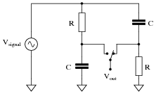
Note: you should be able to do all the necessary math mentally, without the aid of a calculating device!
Reveal Answer
Switch left:
Q = -45
o (V
out lagging behind the source voltage)
Switch right:
Q = +45
o (V
out leading ahead of the source voltage)
Follow-up question: identify the effects of various component failures in this circuit.
Notes:
This is a very interesting circuit to built and test. You may build one using 1 mF capacitors and 2.7 kW resistors that will successfully operate on 60 Hz power-line excitation.
Hide Answer
Question 15:
This interesting bridge circuit is a variable phase-shifter. It works best when the excitation frequency is such that X
C = R in each arm of the bridge:
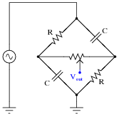
Supposing that X
C does equal R in each arm of the bridge, and that the potentiometer resistance is sufficiently high to limit current through it to a negligible level (in other words, R
pot >> R). Calculate the phase shift of V
out with respect to the excitation source voltage when:
-
�
-
The potentiometer wiper is fully left:
-
�
- The potentiometer wiper is fully right:
-
�
- The potentiometer wiper is perfectly centered:
Reveal Answer
-
�
-
The potentiometer wiper is fully left: Q = -45o
-
�
- The potentiometer wiper is fully right: Q = 45o
-
�
- The potentiometer wiper is perfectly centered: Q = 0o
Follow-up question: this circuit works best with the excitation frequency is such that X
C = R. Write a formula that solves for the necessary frequency (f) to achieve this condition given a certain value of R.
Notes:
This is a very interesting circuit to built and test. You may build one using 1 mF capacitors, 2.7 kW resistors, and a 100 kW potentiometer that will successfully operate on 60 Hz power-line excitation.
An interesting thing to note about using line power is that any distortions in the excitation sine-wave will become obvious when the potentiometer wiper is turned toward the differentiating position (where Q is positive). If listened to with an audio detector, you may even hear the change in timbre while moving the wiper from one extreme to the other. If excited by a "clean" sine-wave, however, no change in timbre should be heard because there are no harmonics present.
Hide Answer
Question 16:
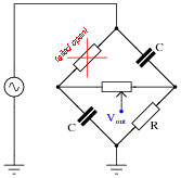
This phase-shifting bridge circuit is supposed to provide an output voltage with a variable phase shift from -45
o (lagging) to +45
o (leading), depending on the position of the potentiometer wiper:
Suppose, though, that there is a solder "bridge" between the terminals of resistor R
1 on the circuit board. What effect will this fault have on the output of the circuit? Be as complete as you can in your answer.
Reveal Answer
With such a ßhorted" failure on R
1, there will be full source voltage at the output with the potentiometer wiper at the full-left position (no attenuation, no phase shift). The output voltage at the full-right wiper position will be mostly unaffected.
Follow-up question: identify another possible component failure that would exhibit the same symptoms.
Notes:
It is essential, of course, that students understand the operational principle of this circuit before they may speculate at the effects of various component faults. You may find it necessary to discuss this circuit in detail with your students before they are ready to troubleshoot it.
In case anyone asks, the symbolism Rpot >> R means "potentiometer resistance is much greater than the fixed resistance value."
Hide Answer
Question 17:
This phase-shifting bridge circuit is supposed to provide an output voltage with a variable phase shift from -45
o (lagging) to +45
o (leading), depending on the position of the potentiometer wiper:

Suppose, though, that the output signal is stuck at +45
o leading the source voltage, no matter where the potentiometer is set. Identify a likely failure that could cause this to happen, and explain why this failure could account for the circuit's strange behavior.
Reveal Answer
A broken connection between the left-hand terminal of the potentiometer and the bridge could cause this to happen:

I'll let you figure out why!
Notes:
It is essential, of course, that students understand the operational principle of this circuit before they may even attempt to diagnose possible faults. You may find it necessary to discuss this circuit in detail with your students before they are ready to troubleshoot it.
In case anyone asks, the symbolism Rpot >> R means "potentiometer resistance is much greater than the fixed resistance value."
Hide Answer
Question 18:
This phase-shifting bridge circuit is supposed to provide an output voltage with a variable phase shift from -45
o (lagging) to +45
o (leading), depending on the position of the potentiometer wiper:

Suppose, though, that the output signal registers as it should with the potentiometer wiper fully to the right, but diminishes greatly in amplitude as the wiper is moved to the left, until there is practically zero output voltage at the full-left position. Identify a likely failure that could cause this to happen, and explain why this failure could account for the circuit's strange behavior.
Reveal Answer
An open failure of the fixed resistor in the upper-left arm of the bridge could cause this to happen:
Follow-up question: identify another possible component failure that would exhibit the same symptoms.
Notes:
It is essential, of course, that students understand the operational principle of this circuit before they may even attempt to diagnose possible faults. You may find it necessary to discuss this circuit in detail with your students before they are ready to troubleshoot it.
In case anyone asks, the symbolism Rpot >> R means "potentiometer resistance is much greater than the fixed resistance value."
Hide Answer
Question 19:
Complex quantities may be expressed in either
rectangular or
polar form. Mathematically, it does not matter which form of expression you use in your calculations.
However, one of these forms relates better to real-world measurements than the other. Which of these mathematical forms (rectangular or polar) relates more naturally to measurements of voltage or current, taken with meters or other electrical instruments? For instance, which form of AC voltage expression, polar or rectangular, best correlates to the total voltage measurement in the following circuit?
Reveal Answer
Polar form relates much better to the voltmeter's display of 5 volts.
Follow-up question: how would you represent the total voltage in this circuit in rectangular form, given the other two voltmeter readings?
Notes:
While rectangular notation is mathematically useful, it does not apply directly to measurements taken with real instruments. Some students might suggest that the 3.000 volt reading and the 4.000 volt reading on the other two voltmeters represent the rectangular components (real and imaginary, respectively) of voltage, but this is a special case. In cases where resistance and reactance are mixed (e.g. a practical inductor with winding resistance), the voltage magnitude will be neither the real nor the imaginary component, but rather the polar magnitude.
Hide Answer
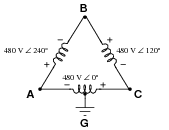
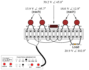
Question 20:
Why are polarity marks (
+ and
-) shown at the terminals of the components in this AC network?
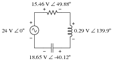
Are these polarity markings really necessary? Do they make any sense at all, given the fact that AC by its very nature has no fixed polarity (because polarity alternates over time)? Explain your answer.
Reveal Answer
The polarity markings provide a frame of reference for the phase angles of the voltage drops.
Notes:
Ask your students why polarity markings need to be provided in DC electrical networks, as an essential part of the voltage figures. Why is an answer for a voltage drop incomplete if not accompanied by polarity markings in a DC circuit? Discuss this with your students, then ask them to extrapolate this principle to AC circuits. When we are accounting for the phase shift of a voltage drop in our answer, does the "polarity" of the voltage drop matter?
Hide Answer
Question 21:
You should know that the line voltage of a three-phase, Y-connected, balanced system is always greater than the phase voltage by a factor of
�3.
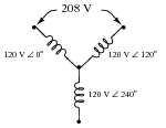
Apply Kirchhoff's Voltage Law (KVL) to the upper "loop" in this Y-connected alternator schematic to prove how 120 V
� 0
o and 120 V
� 120
o makes 208 V. Show the "polarity" marks for each of the voltages as part of your answer.
Reveal Answer
(120 V
� 0
o) - (120 V
� 120
o) = 208 V
� -30
o
(120 V
� 120
o) - (120 V
� 0
o) = 208 V
� 150
o
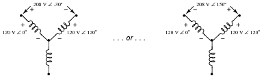
Notes:
This question is highly effective in demonstrating why polarity markings are important in AC circuit analysis. Without the polarity marks as "frames of reference" for the phase angles, it is impossible to determine the resultant line voltage from the two 120 VAC phase voltages.
Hide Answer
Question 22:
Draw a phasor diagram of the voltages in this Delta-connected polyphase system, and use trigonometry to calculate the voltage between points
G and
B.
Reveal Answer
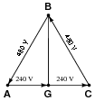
V
BG = 415.7 V
Notes:
Of course, complex numbers may also be used to calculate VAB, but the phasor approach has the benefit of graphical intuitiveness.
Hide Answer
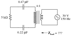
Question 23:
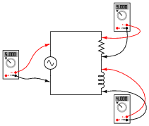
Calculate the load impedance ßeen" by the source, through the ideal transformer with a winding turns ratio of 4:1.
Reveal Answer
Zload = 541.7
W � -54.77
o
Notes:
Ask your students to describe the effect of the transformer's step-up ratio on impedance magnitude and on impedance phase angle. They may do this by comparing the impedance of the C-R-C circuit on the transformer's secondary side versus the impedance ßeen" at the voltage source terminals. Ask them to explain why one of these parameters is affected but the other is not.
Then, pose the scenario of a real transformer, complete with leakage inductance. Ask your students to explain what effect would leakage inductance have on the load impedance of this circuit.
Hide Answer
Question 24:
Calculate all voltage drops in this circuit, expressing your answers in complex (polar) form:
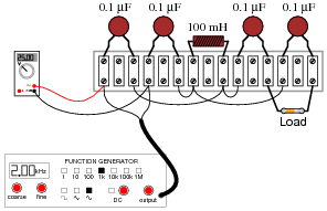
The load resistor's color code is as follows:
Brown, Black, Black, Brown, Violet
Assume the resistor's error is 0%. That is, its resistance value is precisely equal to what the "digit" and "multiplier" color bands declare. The signal generator's output is 25 volts RMS, at a frequency of 2 kHz.
Challenge question: what practical function does this circuit perform?
Reveal Answer
This circuit is a high-pass filter.
Notes:
The real änswer" to this question is the circuit analysis technique employed. Ask your students, perhaps working teams, to explain how to arrive at the different voltage drop figures. Note any similarities in analysis technique to that of DC circuit analysis.
Hide Answer