AC power
Question 1:
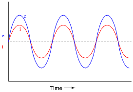
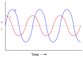
If a sinusoidal voltage is applied to an impedance with a phase angle of 0o, the resulting voltage and current waveforms will look like this:
|
|
Given that power is the product of voltage and current (p = i e), plot the waveform for power in this circuit.
|
|
Notes:
Ask your students to observe the waveform shown in the answer closely, and determine what sign the power values always are. Note how the voltage and current waveforms alternate between positive and negative, but power does not. Of what significance is this to us? What does this indicate about the nature of a load with an impedance phase angle of 0o?
Question 2:
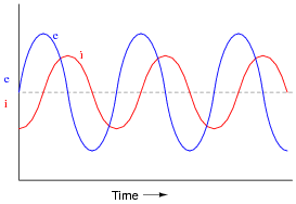
If a sinusoidal voltage is applied to an impedance with a phase angle of 90o, the resulting voltage and current waveforms will look like this:
|
|
Given that power is the product of voltage and current (p = i e), plot the waveform for power in this circuit. Also, explain how the mnemonic phrase ËLI the ICE man" applies to these waveforms.
|
|
The mnemonic phrase, ËLI the ICE man" indicates that this phase shift is due to an inductance rather than a capacitance.
Notes:
Ask your students to observe the waveform shown in the answer closely, and determine what sign the power values are. Note how the power waveform alternates between positive and negative values, just as the voltage and current waveforms do. Ask your students to explain what negative power could possibly mean.
Of what significance is this to us? What does this indicate about the nature of a load with an impedance phase angle of 90o?
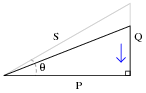
The phrase, ËLI the ICE man" has been used be generations of technicians to remember the phase relationships between voltage and current for inductors and capacitors, respectively. One area of trouble I've noted with students, though, is being able to interpret which waveform is leading and which one is lagging, from a time-domain plot such as this.
Question 3:
If a sinusoidal voltage is applied to an impedance with a phase angle of -90o, the resulting voltage and current waveforms will look like this:
|
|
Given that power is the product of voltage and current (p = i e), plot the waveform for power in this circuit. Also, explain how the mnemonic phrase ËLI the ICE man" applies to these waveforms.
|
|
The mnemonic phrase, ËLI the ICE man" indicates that this phase shift is due to a capacitance rather than an inductance.
Notes:
Ask your students to observe the waveform shown in the answer closely, and determine what sign the power values are. Note how the power waveform alternates between positive and negative values, just as the voltage and current waveforms do. Ask your students to explain what negative power could possibly mean.
Of what significance is this to us? What does this indicate about the nature of a load with an impedance phase angle of -90o?
The phrase, ËLI the ICE man" has been used be generations of technicians to remember the phase relationships between voltage and current for inductors and capacitors, respectively. One area of trouble I've noted with students, though, is being able to interpret which waveform is leading and which one is lagging, from a time-domain plot such as this.
Question 4:
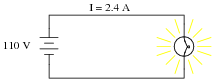
Power is easy to calculate in DC circuits. Take for example this DC light bulb circuit:
|
|
Calculate the power dissipation in this circuit, and describe the transfer of energy from source to load: where does the energy come from and where does it go to?
If the source is a chemical battery, energy comes from the chemical reactions occurring in the battery's electrolyte, becomes transfered to electrical form, and then converted to heat and light in the bulb, all at the rate of 264 Joules per second (J/s).
Notes:
Discuss with your students the one-way flow of energy in a circuit such as this. Although electric current takes a circular path, the actual transfer of energy is one-way: from source to load. This is very important to understand, as things become more complex when reactive (inductive and capacitive) components are considered.
Question 5:
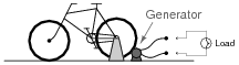
A generator is coupled to a bicycle mechanism, so that a person can generate their own electricity:
|
|
The person pedaling this bicycle/generator notices that it becomes more difficult to pedal when the generator is connected to a load such as a light bulb, or when it is charging a battery. When the generator is open-circuited, however, it is very easy to spin. Explain why this is, in terms of work and energy transfer.
Follow-up question: what would it mean if a generator required no physical effort to turn while it was powering an electrical load?
Notes:
Discuss how the Law of Energy Conservation relates to this scenario.
Question 6:
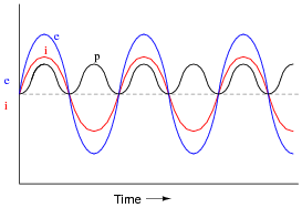
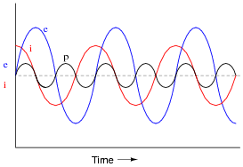
If the power waveform is plotted for a resistive AC circuit, it will look like this:

|
|
What is the significance of the power value always being positive (above the zero line) and never negative (below the zero line)?
Notes:
Ask your students what it means in physical terms for energy to flow to a resistive load, and what it would mean for energy to flow from a resistive load back to the source.
Question 7:
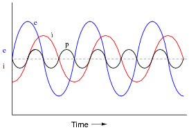
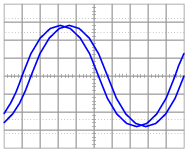
If the power waveform is plotted for an AC circuit with a 90 degree phase shift between voltage and current, it will look something like this:

|
|
What is the significance of the power value oscillating equally between positive (above the zero line) and negative (below the zero line)? How does this differ from a scenario where there is zero phase shift between voltage and current?
Notes:
Discuss with your students the energy-storing and energy-releasing ability of capacitors and inductors, and how they differ from resistors. This is key to understanding the zero net power dissipation of reactive components in AC circuits.
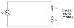
Question 8:
If this circuit is built and operated, it will be found that the resistor becomes much hotter than the inductor, even though both components drop the exact same amount of voltage and carry the exact same amount of current:
|
|
Explain why there is such a remarkable difference in heat output between these two components, given their identical voltage drops and currents.
Notes:
This question seeks to challenge students' perceptions of what constitutes electrical power. From the physical effects described, it is evident that there is more to calculating power than simply multiplying a voltage drop by a current!
Question 9:
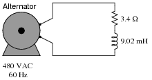
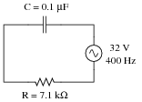
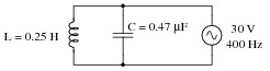
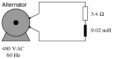
Calculate the current in this circuit, and also the amount of mechanical power (in units of "horsepower") required to turn this alternator (assume 100% efficiency):
|
|
P = 90.8 horsepower
Notes:
Solving this problem requires unit conversions: from "watts" to "horsepower." Let your students research how to perform this conversion, then discuss their various techniques during discussion time.
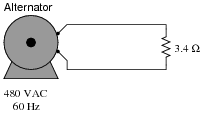
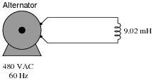
Question 10:
Calculate the current in this circuit, and also the amount of mechanical power (in units of "horsepower") required to turn this alternator (assume 100% efficiency):
|
|
P = 0 horsepower, so long as the inductor is "pure" (100 percent inductance, with no resistance).
Notes:
The answer to this question will surprise many of your students, because they are accustomed to calculating power simply by multiplying voltage by current (P = I E).
Ask your students how they calculated line current in this circuit, and then challenge them with the question of how 0 watts of power can be dissipated in this circuit with all this current and all this voltage (480 volts).
Question 11:
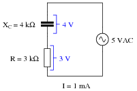
A student is pondering the behavior of a simple series RC circuit:
|
|
It is clear by now that the 4 kW capacitive reactance does not directly add to the 3 kW resistance to make 7 kW total. Instead, the addition of impedances is vectorial:
|
|
|
It is also clear to this student that the component voltage drops form a vectorial sum as well, so that 4 volts dropped across the capacitor in series with 3 volts dropped across the resistor really does add up to 5 volts total source voltage:
|
|
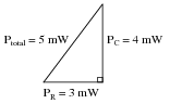
What surprises the student, though, is power. In calculating power for each component, the student arrives at 4 mW for the capacitor (4 volts times 1 milliamp) and 3 mW for the resistor (3 volts times 1 milliamp), but only 5 mW for the total circuit power (5 volts times 1 milliamp). In DC circuits, component power dissipations always added, no matter how strangely their voltages and currents might be related. The student honestly expected the total power to be 7 mW, but that doesn't make sense with 5 volts total voltage and 1 mA total current.
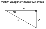
Then it occurs to the student that power might add vectorially just like impedances and voltage drops. In fact, this seems to be the only way the numbers make any sense:
|
|
However, after plotting this triangle the student is once again beset with doubt. According to the Law of Energy Conservation, total power in must equal total power out. If the source is inputting 5 mW of power total to this circuit, there should be no possible way that the resistor is dissipating 3 mW and the capacitor is dissipating 4 mW. That would constitute more energy leaving the circuit than what is entering!
What is wrong with this student's power triangle diagram? How may we make sense of the figures obtained by multiplying voltage by current for each component, and for the total circuit?
|
|
Follow-up question: when making the leap from DC circuit analysis to AC circuit analysis, we needed to expand on our understanding of öpposition" from just resistance (R) to include reactance (X) and (ultimately) impedance (Z). Comment on how this expansion of terms and quantities is similar when dealing with "power" in an AC circuit.
Notes:
The point of this question is to ease the pain of learning about power factor by relating it to a parallel concept: opposition to electric current (R expanding into X and Z). This makes the follow-up question very significant.
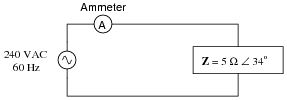
Question 12:
Calculate the current in this circuit, and also the amount of mechanical power (in units of "horsepower") required to turn this alternator (assume 100% efficiency):
|
|
P = 45.4 horsepower
Notes:
Ask students what each of the load components (inductor and resistor) do with the electrical energy delivered to them by the alternator. The two components behave very differently with regard to power, and only one if them is dissipative.
Question 13:
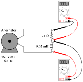
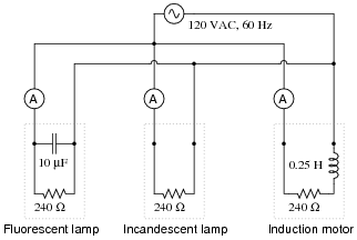
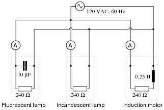
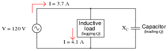
In this circuit, three common AC loads are modeled as resistances, combined with reactive components in two out of the three cases. Calculate the amount of current registered by each ammeter, and also the amount of power dissipated by each of the loads:
|
|
If someone were to read each of the ammeters' indications and multiply the respective currents by the figure of 120 volts, would the resulting power figures (P = I E) agree with the actual power dissipations? Explain why or why not, for each load.
Incandescent lamp: I = 0.5 A ; Actual power = 60 W
Induction motor: I = 0.465 A ; Actual power = 52.0 W
In every load except for the incandescent lamp, more current is drawn from the source than is "necessary" for the amount of power actually dissipated by the load.
Notes:
Your students should realize that the only dissipative element in each load is the resistor. Inductors and capacitors, being reactive components, do not actually dissipate power. I have found that students often fail to grasp the concept of device modeling, instead thinking that the resistances shown in the schematic are actual resistors (color bands and all!). Discuss with them if necessary the concept of using standard electrical elements such as resistors, capacitors, and inductors to simulate characteristics of real devices such as lamps and motors. It is not as though one could take an LCR meter and statically measure each of these characteristics! In each case, the resistance represents whatever mechanism is responsible for converting electrical energy into a form that does not return to the circuit, but instead leaves the circuit to do work.
Ask your students how the ëxcess" current drawn by each load potentially influences the size of wire needed to carry power to that load. Suppose the impedance of each load were 100 times less, resulting in 100 times as much current for each load. Would the ëxtra" current be significant then?
Being that most heavy AC loads happen to be strongly inductive in nature (large electric motors, electromagnets, and the "leakage" inductance intrinsic to large transformers), what does this mean for AC power systems in general?
Question 14:
A very important parameter in AC power circuits is power factor. Explain what "power factor" is, and define its numerical range.
Notes:
This is not the only way to define power factor ([P/S]), but it is perhaps the most straightforward.
Question 15:
Define true power, in contrast to "reactive" or "apparent" power.
Notes:
Ask your students where they found information helpful to answering this question.
Question 16:
Define apparent power, in contrast to "true" or "reactive" power.
Notes:
Ask your students where they found information helpful to answering this question.
Question 17:
Define reactive power, in contrast to "true" or "apparent" power.
Notes:
Ask your students where they found information helpful to answering this question.
Question 18:
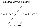
The three different types of power in AC circuits are as follows:
- �
- S = apparent power, measured in Volt-Amps (VA)
- �
- P = true power, measured in Watts (W)
- �
- Q = reactive power, measured in Volt-Amps reactive (VAR)
Explain the names of each of these power types. Why are they called äpparent," "true," and "reactive"?
Notes:
These definitions may be found in any number of textbooks, but that does not mean they are easy to understand. Be sure to discuss these very important concepts with your students, given their tendency to generate confusion!
Question 19:
Power calculation in DC circuits is simple. There are three formulae that may be used to calculate power:
|
Calculating power in AC circuits is much more complex, because there are three different types of power: apparent power (S), true power (P), and reactive power (Q). Write equations for calculating each of these types of power in an AC circuit:
|
|
|
Follow-up question #1: algebraically manipulate each of the following equations to solve for all the other variables in them:
|
Follow-up question #2: substitute p, f, and either L or C into the reactive power equations so that one may calculate Q without having to directly know the value of X.
Notes:
Nothing much to comment on here, as these equations may be found in any number of texts. One thing you might consider doing to encourage participation from your students is to ask three of them to write these equations on the board in front of class, one student per power type (S, P, and Q). This would be an ideal question for your more timid students, because there is little explanation involved and therefore little chance of embarrassment.
Question 20:
Calculate the power factor of this circuit:
|
|
Notes:
In order to solve for power factor, your students must find at least one formula to use for calculating it. There is definitely more than one method of solution here, so be sure to ask multiple students to share their strategies for the benefit of all.
Question 21:
Explain the difference between a leading power factor and a lagging power factor.
Notes:
Ask your students to explain the phase relationships between voltage and current for each of these two conditions: a circuit with a "leading" power factor, and a circuit with a "lagging" power factor. The terms may make a lot more sense once these relationships are seen.
Question 22:
In this circuit, three common AC loads are represented as resistances, combined with reactive components in two out of the three cases. Calculate the amount of true power (P), apparent power (S), reactive power (Q), and power factor (PF) for each of the loads:
|
|
Also, draw power triangle diagrams for each circuit, showing how the true, apparent, and reactive powers trigonometrically relate.
Incandescent lamp: P = 60 W ; Q = 0 VAR ; S = 60 VA ; PF = 1.0
Induction motor: P = 52.0 W ; Q = 20.4 VAR ; S = 55.8 VA ; PF = 0.93, lagging
Notes:
Your students should realize that the only dissipative element in each load is the resistor. Inductors and capacitors, being reactive components, do not actually dissipate power.
Ask your students how the ëxcess" current drawn by each load potentially influences the size of wire needed to carry power to that load. Suppose the impedance of each load were 100 times less, resulting in 100 times as much current for each load. Would the ëxtra" current be significant then?
Being that most heavy AC loads happen to be strongly inductive in nature (large electric motors, electromagnets, and the "leakage" inductance intrinsic to large transformers), what does this mean for AC power systems in general?
Question 23:
Calculate the amount of phase shift between voltage and current in an AC circuit with a power factor of 0.97 (lagging), and an apparent power of 3.5 kVA. Also, write the equation solving for phase shift, in degrees.
Notes:
Ask your students whether this circuit is predominantly capacitive or predominantly inductive, and also how they know it is such.
It is very important for students to be able to solve for angles in simple trigonometric equations, using ärcfunctions," so be sure you discuss the method of solution for this question with your students.
Question 24:
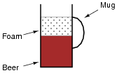
A common analogy used to describe the different types of power in AC circuits is a mug of beer that also contains foam:
|
|
Explain this analogy, relating the quantities of beer and foam to the different types of power in an AC circuit, and also why this analogy is often employed to describe the "desirability" of each power type in a circuit.
Follow-up question: can you think of any potential safety hazards that low power factor may present in a high-power circuit? We're talking AC power circuits here, not beer!
Notes:
Ask your students to apply this analogy to the following AC circuits: how much beer versus foam exists in each one?
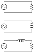
|
|
Question 25:
If an electrical device is modeled by fixed values of resistance, inductance, and/or capacitance, it is not difficult to calculate its power factor:
|
|
|
In real life, though, things are not so simple. An electric motor will not come labeled with an ideal-component model expressed in terms of R and L. In fact, that would be impossible, as the resistance R in the circuit model represents the sum total of mechanical work being done by the motor in addition to the energy losses. These variables change depending on how heavily loaded the motor is, meaning that the motor's power factor will also change with mechanical loading.
However, it may be very important to calculate power factor for electrical loads such as multi-thousand horsepower electric motors. How is this possible to do when we do not know the equivalent circuit configuration or values for such a load? In other words, how do we determine the power factor of a real electrical device as it operates?
|
|
Of course, there do exist special meters to measure true power (wattmeters) and reactive power ("var" meters), as well as power factor directly. Unfortunately, these instruments may not be readily available for our use. What we need is a way to measure power factor using nothing more than standard electrical/electronic test equipment such as multimeters and oscilloscopes. How may we do this?
Hint: remember that the angle Q of the S-Q-P "power triangle" is the same as the angle in a circuit's Z-X-R impedance triangle, and also the same as the phase shift angle between total voltage and total current.
Follow-up question #1: explain how you could safely measure currents in the range of hundreds or thousands of amps, and also measure voltages in the range of hundreds or thousands of volts, using an oscilloscope. Bear in mind that you need to simultaneously plot both variables on the oscilloscope in order to measure phase shift!
Follow-up question #2: explain how you could measure either S, Q, or P using a multimeter.
Notes:
This is a very practical question! There is a lot to discuss here, including what specific devices to use for measuring voltage and current, what safety precautions to take, how to interpret the oscilloscope's display, and so on. Of course, one of the most important aspects of this question to discuss is the concept of empirically determining power factor by measuring a circuit's V/I phase shift.
Question 26:
Suppose that a single-phase AC electric motor is performing mechanical work at a rate of 45 horsepower. This equates to 33.57 kW of power, given the equivalence of watts to horsepower (1 HP � 746 W).
Calculate the amount of line current necessary to power this motor if the line voltage is 460 volts, assuming 100% motor efficiency and a power factor of 1.
Now re-calculate the necessary line current for this motor if its power factor drops to 0.65. Assume the same efficiency (100%) and the same amount of mechanical power (45 HP).
What do these calculations indicate about the importance of maintaining a high power factor value in an AC circuit?
P.F. = 0.65 ; current = 112.3 amps
Follow-up question: what is the ëxtra" current in the 0.65 power factor scenario doing, if not contributing to the motor's mechanical power output?
Notes:
Points of discussion for this question should be rather obvious: why is a current of 112.3 amps worse than a current of 72.98 amps when the exact same amount of mechanical work is being done? What circuit components would have to be oversized to accommodate this extra current?
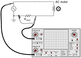
Question 27:
An oscilloscope is connected to a low-current AC motor circuit to measure both voltage and current, and plot them against one another as a Lissajous figure:
|
|
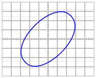
The following Lissajous figure is obtained from this measurement:
|
|
From this figure, calculate the phase angle (Q) and the power factor for this motor circuit.
Follow-up question: is this the only way we could have used the oscilloscope to measure phase shift between voltage and current, or is there another mode of operation besides plotting Lissajous figures?
Notes:
Ask your students to explain the function of the resistor Rshunt shown in the schematic diagram. Discuss whether or not this resistor should have a very low or a very high resistance value. Also discuss the placement of the oscilloscope's ground clip, which is very important in a potentially lethal AC power circuit.
Question 28:
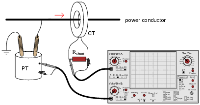
A very high-power AC electric motor needs to have its power factor measured. You and an electrician are asked to perform this measurement using an oscilloscope. The electrician understands what must be done to measure voltage and current in this dangerous circuit, and you understand how to interpret the oscilloscope's image to calculate power factor.
It would be impractical to directly measure voltage and current, seeing as how the voltage is 4160 volts AC and the current is in excess of 200 amps. Fortunately, PT ("potential transformer") and CT ("current transformer") units are already installed in the motor circuit to facilitate measurements:
|
|
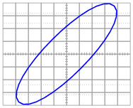
After the electrician helps you safely connect to the PT and CT units, you obtain a Lissajous figure that looks like this:
|
|
Calculate the power factor of the AC motor from this oscilloscope display.
Follow-up question: is it possible to determine which waveform is leading or lagging the other from a Lissajous figure? Explain your answer.
Notes:
This question provides a good opportunity to review the functions of PTs and CTs. Remember that PTs are transformers with precise step-down ratios used to measure a proportion of the line or phase voltage, which in many cases is safer than measuring the line or phase voltage directly. CTs are specially-formed transformers which fit around the current-carrying conductor for the purpose of stepping down current (stepping up voltage) so that a low-range ammeter may measure a fraction of the line current.
Students familiar with large electric motors will realize that a 4160 volt motor is going to be three-phase and not single-phase, and that measuring power factor by means of phase shift between voltage and current may be a bit more complicated than what is shown here. This scenario would work for a Y-connected four-wire, three-phase system, but not all three-phase systems are the same!
Question 29:
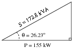
A large electrical load is outfitted with a wattmeter to measure its true power. If the load voltage is 7.2 kV and the load current is 24 amps, calculate the load's apparent power (S). Calculate the power factor and also the phase angle between voltage and current in the circuit if the wattmeter registers 155 kW at those same voltage and current values.
Draw a "power triangle" for this circuit, graphically showing the relationships between apparent power, true power, and phase angle.
|
|
Notes:
This question provides more practice for students with trigonometry, as well as reinforcing the relationships between S, P, Q, and power factor.
Question 30:
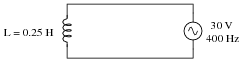
The power factor of this circuit is as low as it can possibly be, 0:
|
|
Calculate the apparent, true, and reactive power for this circuit:
- �
- S =
- �
- P =
- �
- Q =
Now, suppose a capacitor is added in parallel with the inductor:
|
|
Re-calculate the apparent, true, and reactive power for this circuit with the capacitor connected:
- �
- S =
- �
- P =
- �
- Q =
- Without capacitor
- �
- S = 1.432 VA
- �
- P = 0 W
- �
- Q = 1.432 VAR
- With capacitor
- �
- S = 0.369 VA
- �
- P = 0 W
- �
- Q = 0.369 VAR
Notes:
Although the power factor of this circuit is still 0, the total current drawn from the source has been substantially reduced. This is the essence of power factor correction, and the point of this question.
Question 31:
Calculate the line current and power factor in this AC power system:
|
|
Now, calculate the line current and power factor for the same circuit after the addition of a capacitor in parallel with the load:
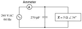
|
|
- Without capacitor
- �
- Iline = 48 A
- �
- P.F. = 0.829
- With capacitor
- �
- Iline = 39.87 A
- �
- P.F. = 0.998
Follow-up question: does the addition of the capacitor affect the amount of current through the 5 W load? Why or why not?
Notes:
The answers to this question may seem really strange to students accustomed to DC circuit calculations, where parallel branch currents always add up to a greater total. With complex numbers, however, the sum is not necessarily greater than the individual values!
Question 32:
It is in the best interest of power distribution systems to maintain the power factors of distant loads as close to unity (1) as possible. Explain why.
Notes:
Ask your students to elaborate on the given answer, explaining why power factor results in excessive line current. Ask them what is meant by the word ëxcessive."
Question 33:
The "power triangle" is a very useful model for understanding the mathematical relationship between apparent power (S), true power (P), and reactive power (Q):
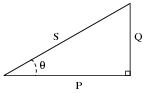
|
|
Explain what happens to the triangle if power factor correction components are added to a circuit. What side(s) change length on the triangle, and what happens to the angle Q?
|
|
Notes:
Ask your students to explain what the "triangle" looks like at a power factor of unity.
Question 34:
When a capacitor is to be connected in parallel with an inductive AC load to correct for lagging power factor, it is important to be able to calculate the reactive power of the capacitor (QC). Write at least one equation for calculating the reactive power of a capacitor (in VARs) given the capacitor's reactance (XC) at the line frequency.
|
Follow-up question: which of the two equations shown above would be easiest to use in calculating the reactive power of a capacitor given the following information?
|
|
Notes:
This step seems to be one of the most difficult for students to grasp as they begin to learn to correct for power factor in AC circuits, so I wrote a question specifically focusing on it. Once students calculate the amount of reactive power consumed by the load (Qload), they may realize the capacitor needs to produce the same (QC), but they often become mired in confusion trying to take the next step(s) in determining capacitor size.
Question 35:
An inductive AC load draws 13.4 amps of current at a voltage of 208 volts. The phase shift between line voltage and line current is measured with an oscilloscope, and determined to be 23o. Calculate the following:
- �
- Apparent power (S) =
- �
- True power (P) =
- �
- Reactive power (Q) =
- �
- Power factor =
An electrician suggests to you that the lagging power factor may be corrected by connecting a capacitor in parallel with this load. If the capacitor is sized just right, it will exactly offset the reactive power of the inductive load, resulting in zero total reactive power and a power factor of unity (1). Calculate the size of the necessary capacitor in Farads, assuming a line frequency of 60 Hz.
- �
- Apparent power (S) = 2.787 kVA
- �
- True power (P) = 2.567 kW
- �
- Reactive power (Q) = 1.089 kVAR
- �
- Power factor = 0.921
- �
- Correction capacitor value = 66.77 mF
Challenge question: write an equation solving for the power factor correction capacitor size (in Farads) given any or all of the variables provided in the question (S, P, Q, f, V, P.F.).
Notes:
There are multiple methods of solution for this problem, so be sure to have your students present their thoughts and strategies during discussion! The formula they write in answer to the challenge question will be nothing more than a formalized version of the solution strategy.
Question 36:
An AC load exhibits a lagging power factor of 0.73 at 230 VAC and 315 amps. If the system frequency is 60 Hz, calculate the following:
- �
- Apparent power (S) =
- �
- True power (P) =
- �
- Reactive power (Q) =
- �
- Q =
- �
- Necessary parallel C size to correct power factor to unity =
- �
- Apparent power (S) = 72.45 kVA
- �
- True power (P) = 52.89 kW
- �
- Reactive power (Q) = 49.52 kVAR
- �
- Q = 43.11o
- �
- Necessary parallel C size to correct power factor to unity = 2,483 mF
Notes:
There are multiple methods of solution for this problem, so be sure to have your students present their thoughts and strategies during discussion!
Question 37:
An inductive AC load consumes 15.2 MW of true power at a voltage of 115 kV and 149.8 amps. If the system frequency is 50 Hz, calculate the following:
- �
- Apparent power (S) =
- �
- Reactive power (Q) =
- �
- Power factor =
- �
- Q =
- �
- Necessary parallel C size to correct power factor to unity =
- �
- Apparent power (S) = 17.23 MVA
- �
- Reactive power (Q) = 8.107 MVAR
- �
- Power factor = 0.882
- �
- Q = 28.1o
- �
- Necessary parallel C size to correct power factor to unity = 1.951 mF
Notes:
There are multiple methods of solution for this problem, so be sure to have your students present their thoughts and strategies during discussion!
Question 38:
A dual-trace oscilloscope is used to measure the phase shift between voltage and current for an inductive AC load:
|
|
Calculate the following, given a load voltage of 110 volts, a load current of 3.2 amps, and a frequency of 60 Hz:
- �
- Apparent power (S) =
- �
- True power (P) =
- �
- Reactive power (Q) =
- �
- Q =
- �
- Power factor =
- �
- Necessary parallel C size to correct power factor to unity =
- �
- Apparent power (S) = 352 VA
- �
- True power (P) = 328.2 W
- �
- Reactive power (Q) = 127.2 VAR
- �
- Q = 21.2o
- �
- Power factor = 0.932
- �
- Necessary parallel C size to correct power factor to unity = 27.9 mF
Follow-up question: identify which waveform represents voltage and which waveform represents current on the oscilloscope display.
Notes:
There are multiple methods of solution for this problem, so be sure to have your students present their thoughts and strategies during discussion!
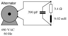
Question 39:
Calculate the power factor of this circuit:
|
|
Then, calculate the size of the capacitor necessary to "correct" the power factor to a value of 1.0, showing the best location of the capacitor in the circuit.
|
|
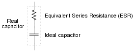
Follow-up question: when we use capacitors as power factor correction components in an AC power system, the equivalent series resistance (ESR) inside the capacitor becomes a significant factor:
|
|
Current through this equivalent series resistance produces heat, and when we're dealing with MVARs worth of reactive power in high-current circuits, this heat can be substantial unless ESR is held low by special capacitor designs. Describe some possible hazards of excessive ESR for a power factor correction capacitor in a high-current circuit.
Challenge question: the ideal location for power factor correction capacitors is at the load terminals, where the reduction in current will be "felt" by all components in the system except the load itself. However, in real life, power factor correction capacitors are often located at the power plant (the alternator). Why would anyone choose to locate capacitors there? What benefit would they provide at all, in that location?
Notes:
Though there are other methods for correcting power factor in AC circuits, the addition of capacitors is perhaps the simplest. Ideally, correction capacitors should be added as close to the load terminals as possible, but in real life they are sometimes located at the power plant (near the alternators). Compare the reduction in conductor currents with the correction capacitor located in different parts of the circuit, and you will see one place in the system where current is reduced no matter where the capacitor is located!
Still, this does not answer the question of why correction capacitors are not always located at the load terminals. Discuss this with your students and see if you can figure out why (hint: what happens when the load's effective resistance changes, as would happen to an electric motor under varying mechanical loads?).
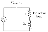
Question 40:
If an AC circuit has a lagging power factor, the way to correct for that power factor is to add a capacitor to the circuit to create leading reactive power. This leading reactive power will cancel the lagging reactive power of the load, ideally negating one another so that there is no reactive power demands placed on the source (zero net reactive power in the circuit):
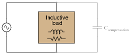
|
|
Define a step-by-step procedure for calculating the size of compensating capacitor needed (in Farads) in order to correct any lagging power factor to a value of unity. Make your procedure general enough that it may apply to any scenario.
- Power factor correction calculation procedure
- �
- �
- �
- �
- �
- �
Notes:
Students generally do not like to explain procedures. They would much rather follow a procedure given by an Authority, because it requires less thinking. It is your responsibility as their instructor to enforce the requirement for thinking in the classroom. It serves your students little to provide them with step-by-step instructions on how to calculate certain things, because ultimately their success will depend on their ability to think deeply and critically, and to problem-solve all on their own.
Answering this question in a group discussion setting need not be intimidating. You may choose to have groups of students answer this question instead of just one or two, or you may even assign this question specifically to a group of students so that there is the impetus of shared responsibility and the safety of friendly assistance in finding an answer.
Question 41:
Most methods of power factor correction involve the connection of a parallel capacitance to an inductive load:
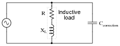
|
|
It is technically possible to correct for lagging power factor by connecting a capacitor in series with an inductive load as well, but this is rarely done:
|
|
Explain why series capacitance is not considered a practical solution for power factor correction in most applications.
Follow-up question: aside from safety, there is also the matter of reliability that concerns us. Examine the parallel-capacitor circuit and the series-capacitor circuit from the perspective of a failed capacitor. Explain how each type of capacitor failure (open versus short) will affect these two circuits.
Notes:
Not only would a series-resonant power circuit be dangerous, but it would also require capacitors rated for handling large continuous currents. The equivalent series resistance (ESR) of the capacitor would have to be very low in order to not experience problems handling full load current for extended periods of time.
It should be mentioned that series capacitors sometimes are used in power systems, most notably at the connection points of some high-voltage distribution lines, at the substation(s).
Question 42:
Although most high-power AC loads are inductive in nature, some are capacitive. Explain what you would have to do to correct for the leading power factor of a large capacitive load, provided the power factor were low enough to warrant the expense of equipment to correct it.
Challenge question: explain how you could exploit the inductive nature of electric motors and other more common load devices in correcting for an excessively low leading power factor.
Notes:
If some students fail to understand the answer to this question, try drawing an üpside-down" power triangle to illustrate:
|
|
Question 43:
In AC power systems, a common way of thinking about reactive power among engineers is in terms of production and consumption. Inductive loads, it is said, consume reactive power. Conversely, capacitive loads produce reactive power.
Explain how the models of "production" and "consumption" relate to reactive power in capacitors and inductors, respectively. Being that neither type of component actually dissipates or generates electrical energy, how can these terms be appropriate in describing their behavior?
Part of the answer to this question lies in the fact that most large AC loads are inductive in nature. From a power plant's perspective, the reactive power of a customer (a "consumer" of power) is inductive in nature, and so that form of reactive power would naturally be considered "consumption."
Notes:
Ask your students this question: if customers on an electrical system "consume" reactive power, then who has the job of supplying it? Carrying this question a bit further, are the alternators used to generate power rated in watts or in volt-amps? Is it possible for an alternator to supply an infinite amount of purely reactive power, or is there some kind of limit inherent to the device? To phrase the question another way, does the necessity of ßupplying" reactive power to customers limit the amount of true power than a power plant may output?
Question 44:
Another name for "capacitor" is condenser. Explain what a synchronous condenser is, and how it is used to correct power factor in AC power systems.
Challenge question: capacitors are considered reactive devices because they have to ability to store and release energy. How would a synchronous condenser store and release energy, seeing as it does not make use of electric fields as capacitors do?
Notes:
There is a fair amount of information available on the internet and also in power engineering texts on the subject of synchronous condensers, although this mature technology is being superseded by solid-state static VAR compensator circuits which have no moving parts.
You might wish to mention that most AC generators (alternators) have the ability to run as synchronous motors, and therefore as synchronous condensers. It is commonplace for spare generators at power plants to be ïdled" as electric motors and used to generate leading VARs to reduce heating in the windings of the other generators. This is especially true at hydroelectric dams, where frequent shut-downs and start-ups of generator units is discouraged due to the massive size of the units and the physical wear incurred during that cycling.
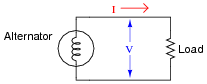
Question 45:
Calculating apparent power for a single-phase AC circuit is easy - simply multiply line voltage by line current (S = VI):
|
|
How do we calculate apparent power in a balanced three-phase circuit, given the same figures?
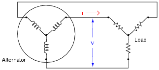
|
|
Follow-up question: suppose the three-phase system were a Delta configuration instead of a Wye configuration. Does this influence the apparent power calculation? Why or why not?
Notes:
The formula for calculating power in a balanced three-phase system may be found in any textbook. Let your students do the necessary research!
Question 46:
A very large 3-phase alternator at a hydroelectric dam has the following continuous full-power ratings:
- �
- 600 MW power output
- �
- 15 kV line voltage
- �
- 23.686 kA line current
Calculate the continuous full-load apparent power for this alternator (in MVA), its continuous full-load reactive power (in MVAR), and its power factor (in percent).
Notes:
These figures came from a real hydroelectric generator that I saw once on a tour. Needless to say, this alternator was very large!
- �
- Maximum continuous ratings
- �
- 615.38 MVA apparent power output
- �
- 600 MW true power output
- �
- 15 kV line voltage
- �
- 23.686 kA line current
- �
- 97.5% power factor
- �
- 365 volts exciter voltage
- �
- 3,425 amps exciter current
- �
- Maximum continuous overload ratings
- �
- 707.69 MVA apparent power output
- �
- 690 MW true power output
- �
- 15 kV line voltage
- �
- 27.239 kA line current
- �
- 97.5% power factor
- �
- 410 volts exciter voltage
- �
- 3,640 amps exciter current
Question 47:
Large power distribution centers are often equipped with capacitors to correct for lagging (inductive) power factor of many industrial loads. There is never any one value for capacitance that will precisely correct for the power factor, though, because load conditions constantly change. At first it may seem that a variable capacitor would be the answer (adjustable to compensate for any value of lagging power factor), but variable capacitors with the ratings necessary for power line compensation would be prohibitively large and expensive.
One solution to this problem of variable capacitance uses a set of electromechanical relays with fixed-value capacitors:
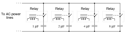
|
|
Explain how a circuit such as this provides a step-variable capacitance, and determine the range of capacitance it can provide.
Notes:
Although semiconductor-based static VAR compensator circuits are now the method of choice for modern power systems, this technique is still valid and is easy enough for beginning students to comprehend. A circuit such as this is a great application of the binary number system, too!