Basic ammeter use
Question 1:
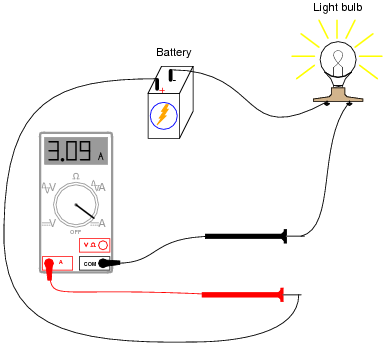
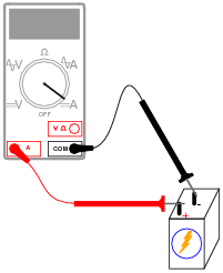
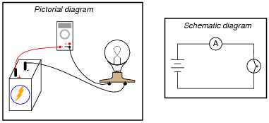
Show how this ammeter would be connected to the light bulb circuit to measure the circuit's electric current:

|
|
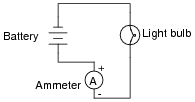
Also, draw a schematic diagram of this same circuit (with the ammeter connected).
|
|
(Note: the meter's indication of 3.09 amps is arbitrary, and not important to the question).
|
|
Notes:
The important thing for students to understand in this question is that the ammeter must become part of the path that the electric current flows through. Explain how this fact contains an element of danger, as contrasted against the relatively "non-invasive" connection of a voltmeter to a circuit.
Question 2:
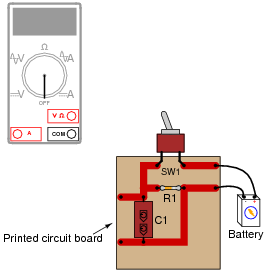
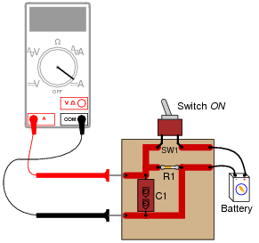
Shown here is a circuit constructed on a PCB (a "Printed Circuit Board"), with copper "traces" serving as wires to connect the components together:
|
|
How would the multimeter be used to measure the current through the component labeled "R1" when energized? Include these important points in your answer:
- �
- The configuration of the multimeter (selector switch position, test lead jacks)
- �
- The connections of the meter test leads to the circuit
- �
- The state of the switch on the PCB (open or closed)
|
|
In order to measure current through resistor R1, one of its leads must be de-soldered from the circuit board so that the meter may be connected directly in-line (in series) with it.
Notes:
Many multimeters use ïnternational" symbols to label DC and AC selector switch positions. It is important for students to understand what these symbols mean.
As you can see in this answer, measuring current through components is generally more difficult than measuring voltage across components, and involves greater risk because the meter must conduct the component's full current (which in some cases may be significant). For this reason, technicians need to learn troubleshooting techniques prioritizing voltage measurements over current measurements.
Question 3:
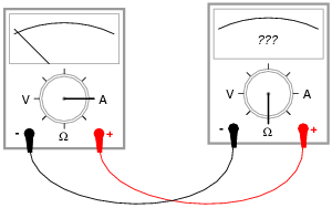
Why is it a very bad idea to connect an ammeter directly across a voltage source, like this?
|
|
In applications where the voltage source possesses very little internal resistance of its own, the current surge resulting from such a short-circuit may be huge. Very large surges of electric current are capable of heating wires to the point where their insulation bursts into flames, as well as causing super-heated blasts of plasma (electrically ionized gas) to form at any point of electrical contact where there is a spark. Either of these high-temperature conditions are hazardous to the person holding the meter and test leads!
Notes:
An important point to discuss is how electrical safety encompasses more than just shock hazard. In particular, arc blasts caused by high-current "faults" such as this may be just as dangerous as electric shock. At the very least, placing an ammeter directly across the terminals of a voltage source will likely result in the ammeter's fuse being blown.
In some cases, ammeter fuses are more expensive than one might think. Safety-rated ammeters often use expensive fast-action fuses with significant current interruption ratings. In the case of the Fluke 187 and 189 multimeters, these fuses cost around $8 each (American dollars, 2004)!
Question 4:
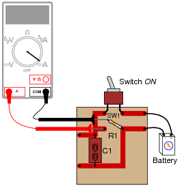
What would happen if a multimeter were connected across the component labeled "C1" on this printed circuit board, as shown?
|
|
Notes:
Even though it might not appear that the meter is ßhorting" the battery in this example, it most certainly is. In asking students to determine the resulting damage from such an action, it is important for them to trace the path of "fault current" through the circuit. Those components within the path of fault current are in risk of damage, while those components not within the path of fault current are not at risk.
Question 5:
If we were to connect an ammeter directly to an ohmmeter, what would you expect to see the ohmmeter register, for resistance between its test leads?
|
|
Notes:
Ask your students why an ammeter should have a very low resistance (fractions of an ohm) between its test leads. How does this property of all ammeters relate to how they are used to measured current in real circuits?
Question 6:
Most ammeters contain fuses inside to provide protection for the person using the ammeter, as well as for the ammeter mechanism itself. Voltmeters generally do not contain fuses inside, because they are unnecessary.
Explain why ammeters use fuses and voltmeters do not? What is it about the nature of an ammeter and how it is used that makes fuse-protection necessary?
Notes:
This is a very important question for several reasons. First, it alerts students that ammeters are generally fuse-protected, and therefore they must be aware that this fuse could "blow" and render the ammeter inoperative. Secondly, it highlights one of the major differences between voltmeters and ammeters, and that is the amount of current typically handled by the respective meter types.
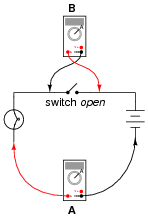
Question 7:
In this circuit, is the light bulb lit? Why or why not?
Also, compare the relative indications of the two ammeters (which ammeter registers the greatest amount of current, and which ammeter registers the least amount of current, or do they both register the same amount of current?).
|
|
Notes:
It is vitally important for students to understand the significance of continuity throughout the entire circuit, not just at one or more points in the circuit.
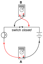
Question 8:
In this circuit, is the light bulb lit? Why or why not?
Also, compare the relative indications of the two ammeters (which ammeter registers the greatest amount of current, and which ammeter registers the least amount of current, or do they both register the same amount of current?).
|
|
Notes:
This is a good question to engage students' thinking on meter properties. A voltmeter does not function the same as an ammeter, and the two different types of meters will impact circuits differently when connected! Incidentally, ammeters tend to get you into more trouble than voltmeters when troubleshooting circuits, which is why students should be encouraged to use a voltmeter whenever possible rather than an ammeter. Of course, clamp-on ammeters are not as unsafe as ammeters requiring direct connection with circuit conductors.
Question 9:
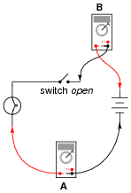
In this circuit, is the light bulb lit? Why or why not?
Also, compare the relative indications of the two ammeters (which ammeter registers the greatest amount of current, and which ammeter registers the least amount of current, or do they both register the same amount of current?).
|
|
Notes:
Exactly what ammeter "B" will register (aside from its indication being less then ammeter Ä"), is an interesting question.
Question 10:
Generally speaking, is an ammeter supposed to be connected in series or in parallel with the component it's measuring current through?
Notes:
If your students don't already know, this question is an excellent opportunity for them to learn about what a ßeries" circuit is and how it differs from a "parallel" circuit. Ask your students why ßeries" is the correct answer. What is it about a series connection that makes it the best type of connection to use an ammeter in? What would happen if we connected an ammeter in parallel with a circuit component?
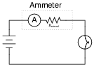
Question 11:
Ammeters must be connected in series with the current to be measured, to ensure that all the current moves through the meter:
|
|
In order to practically function, an ammeter must have some internal resistance. It is usually a very small amount, but it does exist. It should be apparent to you that the presence of this resistance will have some effect on the circuit current, when compared to the amount of current in the circuit without any meter connected:
|
|
Explain why it is usually safe to ignore the internal resistance of an ammeter, though, when it is in a circuit. A common term used in electrical engineering to describe this intentional oversight is swamping. In this particular circuit an engineer would say, "The resistance of the light bulb swamps the internal resistance of the ammeter."
Notes:
I have found that the concept of "swamping" is extremely useful when making estimations. To be able to ignore the values of some components allows one to simplify a great many circuits, enabling easier calculations to be performed.