Performance-based assessments for AC circuit competencies
Question 1:
| (Template) |
|
|
Notes:
Any relevant notes for the assessment activity go here.
Question 2:
|
|
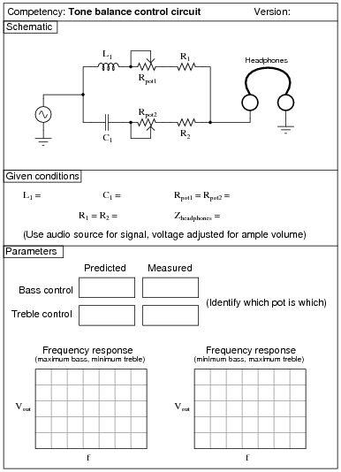
Note: when testing the frequency response of the tone control circuit, you may need to replace the headphones with a non-inductive resistor of equivalent impedance, and measure Vout across it.
Notes:
A good source of audio signal is the headphone output jack of almost any radio, media player, or other portable audio device. Students like being able to do a lab exercise that directly relates to technology they're already familiar with.
The higher-impedance the headphones are, the better this circuit works, since the combination of potentiometers and mixing resistors tends to result in a relatively high output impedance. I have used cheap headphones (32 ohm) with some success, given the following component values:
- �
- C1 = 0.1 mF
- �
- L1 = 200 mH (actually two 100 mH inductors in series)
- �
- R1 = R2 = 1 kW
- �
- Rpot1 = Rpot2 = 10 kW
Some students with limited hearing range have difficulty detecting the changes in tone using 10 kW potentiometers. You may wish to use 100 kW potentiometers instead for added attenuation. Operating such a circuit is akin to operating a water faucet with "hot" and "cold" water valves: the two settings together determine temperature and flow (tone and volume, respectively, for the metaphorically challenged).
An extension of this exercise is to incorporate troubleshooting questions. Whether using this exercise as a performance assessment or simply as a concept-building lab, you might want to follow up your students' results by asking them to predict the consequences of certain circuit faults.
If you plan to use this exercise as a troubleshooting assessment, I recommend against inducing the following component failures, as they are difficult to detect when the signal source is music rather than a constant tone of known frequency and amplitude:
- �
- Shorted capacitor (C1)
- �
- Shorted inductor (L1)
- �
- Shorted fixed-value resistors (R1 or R2)
Question 3:
|
|
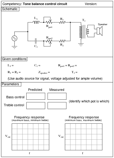
Note: when testing the frequency response of the tone control circuit, you may need to replace the transformer/speaker assembly with a non-inductive resistor of equivalent impedance, and measure Vout across it.
Notes:
A good source of audio signal is the headphone output jack of almost any radio, media player, or other portable audio device. Students like being able to do a lab exercise that directly relates to technology they're already familiar with.
I have experienced good success with the following component values:
- �
- C1 = 0.1 mF
- �
- L1 = 200 mH (actually two 100 mH inductors in series)
- �
- R1 = R2 = 1 kW
- �
- T1 = 1000:8 ohm audio output transformer
- �
- Rpot = Rpot2 = 10 kW
- �
- Speaker = small 8 W unit (salvaged from an old clock radio or other inexpensive audio device)
An extension of this exercise is to incorporate troubleshooting questions. Whether using this exercise as a performance assessment or simply as a concept-building lab, you might want to follow up your students' results by asking them to predict the consequences of certain circuit faults.
Question 4:

|
|
Notes:
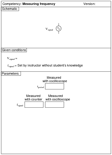
Use a sine-wave function generator for the AC voltage source, and be sure set the frequency to some reasonable value (well within the capability of both the oscilloscope and counter to measure).
If this is not the first time students have done this, be sure to "mess up" the oscilloscope controls prior to them making adjustments. Students must learn how to quickly configure an oscilloscope's controls to display any arbitrary waveform, if they are to be proficient in using an oscilloscope as a diagnostic tool.
Question 5:
|
|
Notes:
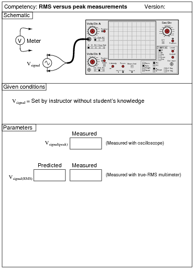
Use a sine-wave function generator for the AC voltage source, and be sure set the frequency to some reasonable value (well within the capability of a multimeter to measure). It is very important that students learn to convert between peak and RMS measurements for sine waves, but you might want to mix things up a bit by having them do the same with triangle waves and square waves as well! It is vital that students realize the rule of VRMS = [(Vpeak)/(�2)] only holds for sinusoidal signals.
If you do choose to challenge students with non-sinusoidal waveshapes, be very sure that they do their voltmeter measurements using true-RMS meters! This means no analog voltmeters, which are "miscalibrated" so their inherently average-responding movements register (sinusoidal) RMS accurately. Your students must use true-RMS digital voltmeters in order for their non-sinusoidal RMS measurements to correlate with their calculations.
Incidentally, this lab exercise also works well as a demonstration of the importance of true-RMS indicating meters, comparing the indications of analog, non-true-RMS digital, and true-RMS digital on the same non-sinusoidal waveform!
Question 6:
|
|
Notes:
Use a sine-wave function generator for the AC voltage source, and be sure set the frequency to some reasonable value (well within the capability of both the oscilloscope and counter to measure).
Question 7:
|
|
Notes:
Use a sine-wave function generator for the AC voltage source. I recommend against using line-power AC because of strong harmonic frequencies which may be present (due to nonlinear loads operating on the same power circuit). Specify a standard inductor value.
If students are to use a multimeter to make their current and voltage measurements, be sure it is capable of accurate measurement at the circuit frequency! Inexpensive digital multimeters often experience difficulty measuring AC voltage and current toward the high end of the audio-frequency range.
Question 8:
|
|
Notes:
Use a sine-wave function generator for the AC voltage source. I recommend against using line-power AC because of strong harmonic frequencies which may be present (due to nonlinear loads operating on the same power circuit). Specify standard resistor and inductor values.
If students are to use a multimeter to make their current and voltage measurements, be sure it is capable of accurate measurement at the circuit frequency! Inexpensive digital multimeters often experience difficulty measuring AC voltage and current toward the high end of the audio-frequency range.
An extension of this exercise is to incorporate troubleshooting questions. Whether using this exercise as a performance assessment or simply as a concept-building lab, you might want to follow up your students' results by asking them to predict the consequences of certain circuit faults.
Question 9:
|
|
Notes:
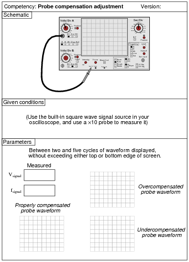
If the oscilloscope does not have its own internal square-wave signal source, use a function generator set up to output square waves at 1 volt peak-to-peak at a frequency of 1 kHz.
If this is not the first time students have done this, be sure to "mess up" the oscilloscope controls prior to them making adjustments. Students must learn how to quickly configure an oscilloscope's controls to display any arbitrary waveform, if they are to be proficient in using an oscilloscope as a diagnostic tool.
Question 10:
|
|
Notes:
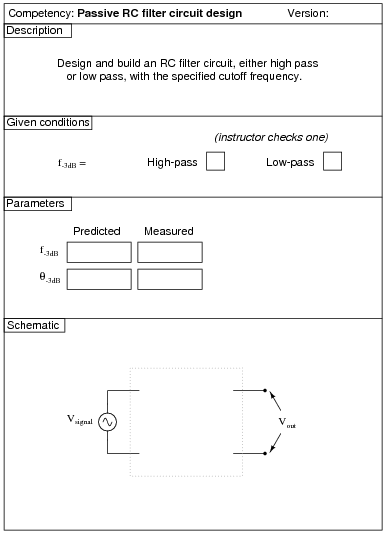
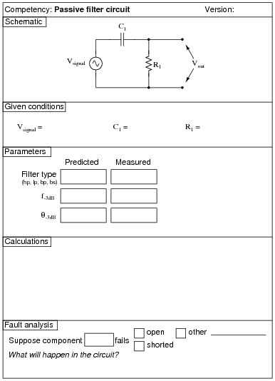
Use a sine-wave function generator for the AC voltage source. Specify a cutoff frequency within the audio range.
I recommend setting the function generator output for 1 volt, to make it easier for students to measure the point of "cutoff". You may set it at some other value, though, if you so choose (or let students set the value themselves when they test the circuit!).
I also recommend having students use an oscilloscope to measure AC voltage in a circuit such as this, because some digital multimeters have difficulty accurately measuring AC voltage much beyond line frequency range. I find it particularly helpful to set the oscilloscope to the "X-Y" mode so that it draws a thin line on the screen rather than sweeps across the screen to show an actual waveform. This makes it easier to measure peak-to-peak voltage.
Question 11:
|
|
Notes:
The real challenge in this assessment is for students to determine their transformers' "polarities" before connecting them to the AC voltage source! For this, they should have access to a small battery and a DC voltmeter (at their desks).
You may use a Variac at the test bench to provide variable-voltage AC power for the students' transformer circuits. I recommend specifying load resistance values low enough that the load current completely ßwamps" the transformer's magnetization current. This may mean using wire-wound power resistors instead of [1/4] watt carbon composition resistors.
Note that there may very well be a shock hazard associated with this circuit! Be sure to take this into consideration when specifying load resistor values. You may also want to use low supply voltage levels (turn the Variac way down).
An extension of this exercise is to incorporate troubleshooting questions. Whether using this exercise as a performance assessment or simply as a concept-building lab, you might want to follow up your students' results by asking them to predict the consequences of certain circuit faults.
Question 12:
|
|
Notes:
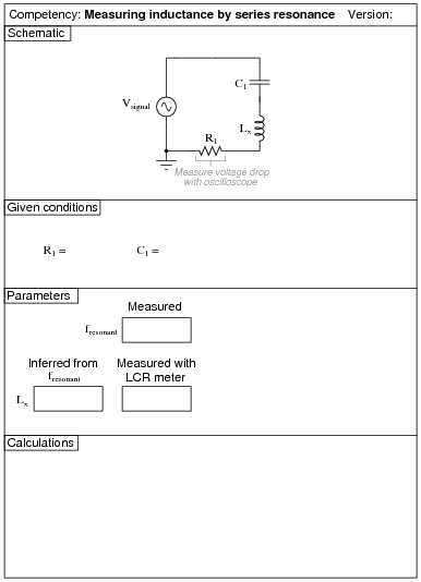
This is perhaps the most reliable means of measuring inductance without an impedance bridge or an LCR meter. You may wish to ask your students to explain why this method of measurement is so good (hint: they must explain why the inductor's intrinsic resistance has no effect on the measurement).
I prefer this particular circuit design for L measurement because series resistance does not skew the resonant point, and because the series capacitor prevents any possible DC current from "biasing" the inductor's core.
If your students own high-quality multimeters capable of measuring audio-frequency AC current and frequency, then the best way to do this is to replace the resistor R1 with their ammeters. Otherwise, use an oscilloscope to measure (maximum) voltage dropped across R1.
In order to obtain good measurements using this technique, I recommend following these guidelines:
- �
- Choose a value of R1 low enough to give a sharp bandwidth, but not so low that the voltage signal dropped across it is "fuzzy" with noise and difficult to accurately discern the period of.
- �
- Choose a value for C1 as low as possible to give sharp bandwidth (thereby maximizing the L/C ratio), without pushing the circuit's resonant frequency too close to the inductor's self-resonant frequency.
- �
- Avoid frequencies above the audio range, lest your students measure the inductor's self-resonant point!
- �
- Use minimal output from the signal generator, to avoid voltage and current levels that will approach core saturation in the inductor.
I've had fair results using one of the windings of a small audio output transformer (center-tapped 1000 W primary winding, with 8 W secondary winding) as the inductor, connected in series with either a 0.1 mF or a 0.47 mF metal-film capacitor, all in series with a 100 ohm resistor. For best results, of course, pre-measure the value of the capacitor rather than go by its advertised value.
I have also used a 100 mH inductor (nominal), in series with a 0.033 mF capacitor and 100 W resistor, with good results.
Question 13:
|
|
Notes:
Use a sine-wave function generator for the AC voltage source. Specify standard resistor, capacitor, and inductor values. I have used a small 100 mH inductor, a 0.033 mF capacitor, and 100 W resistor with good success. In any case I recommend keeping the resonant frequency within the mid-audio range (1 kHz to 10 kHz) to avoid problems with low inductor Q (frequency too low) and stray capacitance and inductance issues (frequency too high).
I also recommend having students use an oscilloscope to measure AC voltage in a circuit such as this, because some digital multimeters have difficulty accurately measuring AC voltage much beyond line frequency range. I find it particularly helpful to set the oscilloscope to the "X-Y" mode so that it draws a thin line on the screen rather than sweeps across the screen to show an actual waveform. This makes it easier to measure peak-to-peak voltage.
An extension of this exercise is to incorporate troubleshooting questions. Whether using this exercise as a performance assessment or simply as a concept-building lab, you might want to follow up your students' results by asking them to predict the consequences of certain circuit faults.
Question 14:
|
|
Notes:
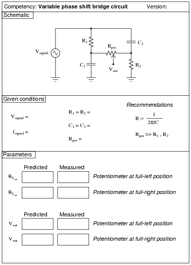
This is a very interesting circuit to built and test. You may build one using 1 mF capacitors, 2.7 kW resistors, and a 100 kW potentiometer that will successfully operate on 60 Hz power-line excitation. If you prefer to use audio frequency power, try 0.047 mF capacitors, 1 kW resistors, a 100 kW potentiometer, and 3.386 kHz for the source frequency.
An interesting thing to note about using line power is that any distortions in the excitation sine-wave will become obvious when the potentiometer wiper is turned toward the differentiating position (where Q is positive). If listened to with an audio detector, you may even hear the change in timbre while moving the wiper from one extreme to the other. If excited by a "clean" sine-wave, however, no change in timbre should be heard because there are no harmonics present.
Question 15:
|
|
Notes:
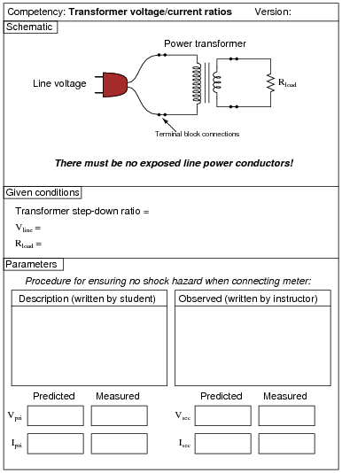
Use line-frequency power transformers for this exercise, with load resistor values low enough to ßwamp" the primary winding's excitation current, so that the primary/secondary current ratio is realistic. Choosing a resistor value low enough to load the transformer near 100 % rated secondary current is a good start. Be careful that your load resistor can handle the power dissipation!
It might be a good idea for students to take careful measurements of primary and secondary voltage in an unloaded condition in order to calculate the actual winding turns ratio of their transformer. Knowing this precise ratio will be helpful to them later on when they use their transformers in other performance assessment activities, so their predictions will more closely match their actual measurements.
An extension of this exercise is to incorporate troubleshooting questions. Whether using this exercise as a performance assessment or simply as a concept-building lab, you might want to follow up your students' results by asking them to predict the consequences of certain circuit faults.
Question 16:
|
|
Notes:
The real challenge in this assessment is for students to determine their transformers' "polarities" before connecting them to the AC voltage source! For this, they should have access to a small battery and a DC voltmeter (at their desks).
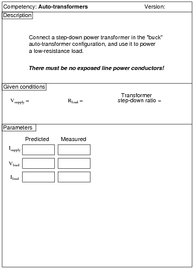
You may use a Variac at the test bench to provide variable-voltage AC power for the students' transformer circuits. I recommend specifying load resistance values low enough that the load current completely ßwamps" the transformer's magnetization current. This may mean using wire-wound power resistors instead of [1/4] watt carbon composition resistors.
Note that there may very well be a shock hazard associated with this circuit, as the output voltage is not far below the line voltage! Be sure to take this into consideration when specifying load resistor values. You may also want to use low supply voltage levels (turn the Variac way down).
In lieu of using a line-powered transformer, you may also do this exercise with a signal generator and an audio-frequency transformer. The principles are the same, and the safety hazard will be vastly reduced. If using a 1000:8 ohm transformer, the winding turns ratio is approximately 11.18 to 1.
An extension of this exercise is to incorporate troubleshooting questions. Whether using this exercise as a performance assessment or simply as a concept-building lab, you might want to follow up your students' results by asking them to predict the consequences of certain circuit faults.
Question 17:
|
|
Notes:
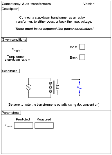
The real challenge in this assessment is for students to determine their transformers' "polarities" before connecting them to the AC voltage source! For this, they should have access to a small battery and a DC voltmeter (at their desks).
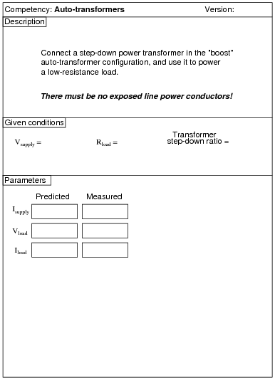
You may use a Variac at the test bench to provide variable-voltage AC power for the students' transformer circuits. I recommend specifying load resistance values low enough that the load current completely ßwamps" the transformer's magnetization current. This may mean using wire-wound power resistors instead of [1/4] watt carbon composition resistors.
Note that there may very well be a shock hazard associated with this circuit, as you are "boosting" the supply voltage! Be sure to take this into consideration when specifying load resistor values. You may also want to use low supply voltage levels (turn the Variac way down).
An extension of this exercise is to incorporate troubleshooting questions. Whether using this exercise as a performance assessment or simply as a concept-building lab, you might want to follow up your students' results by asking them to predict the consequences of certain circuit faults.
Question 18:
|
|
Notes:
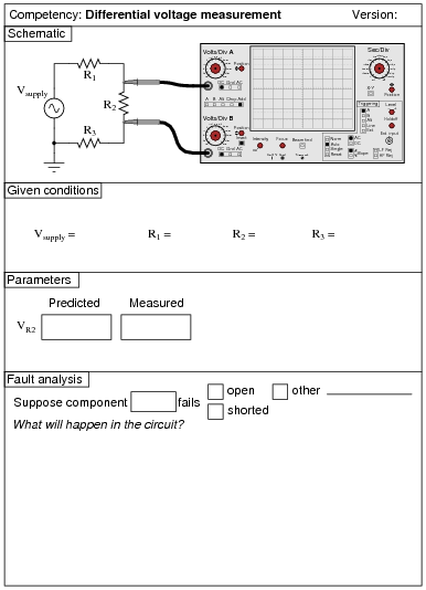
The nature of the AC signal source is not crucial, so long as an accurate peak measurement may be obtained. I recommend specifying equal-value resistors to make the voltage drop calculation as easy as possible. The purpose of this exercise is not how to calculate voltage divider outputs, but rather how to utilize both inputs of a dual-trace oscilloscope to perform differential voltage measurements.
Question 19:
|
|
Notes:
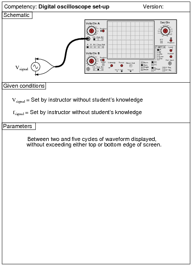
Use a sine-wave function generator for the AC voltage source, and be sure set the frequency to some reasonable value (well within the capability of both the oscilloscope and counter to measure).
Some digital oscilloscopes have äuto set" controls which automatically set the vertical, horizontal, and triggering controls to "lock in" a waveform. Be sure students are learning how to set up these controls on their own rather than just pushing the äuto set" button!
Question 20:
|
|
Notes:
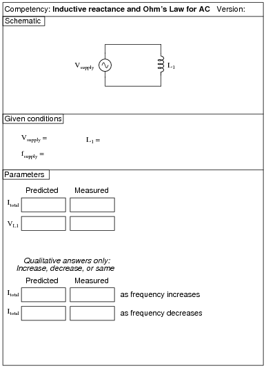
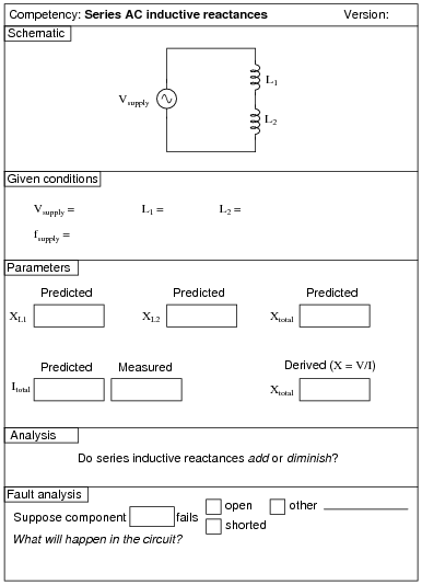
Use a sine-wave function generator for the AC voltage source. I recommend against using line-power AC because of strong harmonic frequencies which may be present (due to nonlinear loads operating on the same power circuit). Specify standard inductor values. If the inductors are not well shielded, be sure to keep them adequately separated so as to avoid mutual inductance!
If students are to use a multimeter to make their current and voltage measurements, be sure it is capable of accurate measurement at the circuit frequency! Inexpensive digital multimeters often experience difficulty measuring AC voltage and current toward the high end of the audio-frequency range.
Question 21:
|
|
Notes:
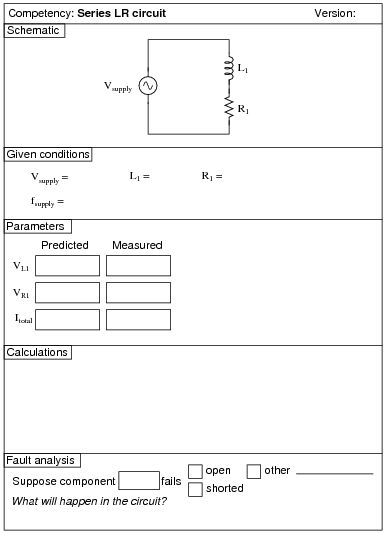
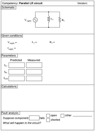
Use a sine-wave function generator for the AC voltage source. I recommend against using line-power AC because of strong harmonic frequencies which may be present (due to nonlinear loads operating on the same power circuit). Specify standard resistor and inductor values, and select a frequency that results in the inductor having a high Q value, so that its parasitic resistance does not become a significant factor in the calculations.
If students are to use a multimeter to make their current and voltage measurements, be sure it is capable of accurate measurement at the circuit frequency! Inexpensive digital multimeters often experience difficulty measuring AC voltage and current toward the high end of the audio-frequency range.
An extension of this exercise is to incorporate troubleshooting questions. Whether using this exercise as a performance assessment or simply as a concept-building lab, you might want to follow up your students' results by asking them to predict the consequences of certain circuit faults.
Question 22:
|
|
Notes:
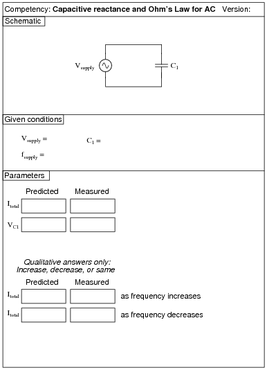
Use a sine-wave function generator for the AC voltage source. I recommend against using line-power AC because of strong harmonic frequencies which may be present (due to nonlinear loads operating on the same power circuit). Specify a standard capacitor value.
If students are to use a multimeter to make their current and voltage measurements, be sure it is capable of accurate measurement at the circuit frequency! Inexpensive digital multimeters often experience difficulty measuring AC voltage and current toward the high end of the audio-frequency range.
Question 23:
|
|
Notes:
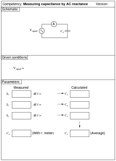
Use a sine-wave function generator for the AC voltage source. I recommend against using line-power AC because of strong harmonic frequencies which may be present (due to nonlinear loads operating on the same power circuit). Specify a standard capacitor value.
If students are to use a multimeter to make their current and voltage measurements, be sure it is capable of accurate measurement at the circuit frequency! Inexpensive digital multimeters often experience difficulty measuring AC voltage and current toward the high end of the audio-frequency range.
Question 24:
|
|
Notes:
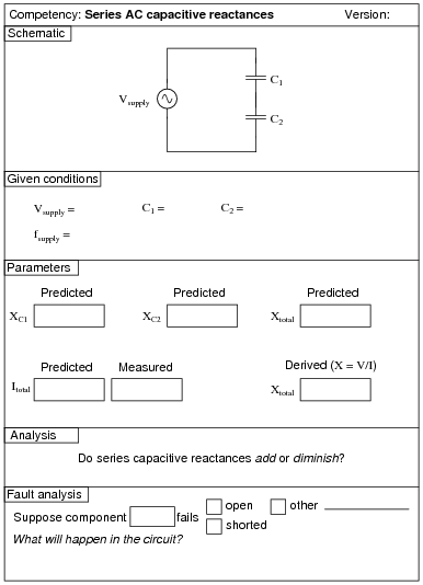
Use a sine-wave function generator for the AC voltage source. I recommend against using line-power AC because of strong harmonic frequencies which may be present (due to nonlinear loads operating on the same power circuit). Specify standard capacitor values.
If students are to use a multimeter to make their current and voltage measurements, be sure it is capable of accurate measurement at the circuit frequency! Inexpensive digital multimeters often experience difficulty measuring AC voltage and current toward the high end of the audio-frequency range.
Students often become confused when learning about series and parallel capacitive reactances, because many think capacitors are inherently öpposite" of inductors and resistors in all respects. In other words, they first learn that capacitance (measured in Farads) adds in parallel and diminishes in series, and that this is just the opposite of resistance (Ohms) and inductance (Henrys), and they mistakenly carry this thinking on through capacitive reactance (Ohms) as well. The real lesson of this exercise is that reactances add in series, regardless of their nature.
Question 25:
|
|
Notes:
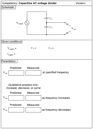
Use a sine-wave function generator for the AC voltage source. I recommend against using line-power AC because of strong harmonic frequencies which may be present (due to nonlinear loads operating on the same power circuit). Specify standard capacitor values.
If students are to use a multimeter to make their current and voltage measurements, be sure it is capable of accurate measurement at the circuit frequency! Inexpensive digital multimeters often experience difficulty measuring AC voltage and current toward the high end of the audio-frequency range.
An extension of this exercise is to incorporate troubleshooting questions. Whether using this exercise as a performance assessment or simply as a concept-building lab, you might want to follow up your students' results by asking them to predict the consequences of certain circuit faults.
Question 26:
|
|
Notes:
Use a sine-wave function generator for the AC voltage source. I recommend against using line-power AC because of strong harmonic frequencies which may be present (due to nonlinear loads operating on the same power circuit). Specify standard resistor and capacitor values.
If students are to use a multimeter to make their current and voltage measurements, be sure it is capable of accurate measurement at the circuit frequency! Inexpensive digital multimeters often experience difficulty measuring AC voltage and current toward the high end of the audio-frequency range.
An extension of this exercise is to incorporate troubleshooting questions. Whether using this exercise as a performance assessment or simply as a concept-building lab, you might want to follow up your students' results by asking them to predict the consequences of certain circuit faults.
Question 27:
|
|
Notes:
Use a sine-wave function generator for the AC voltage source. I recommend against using line-power AC because of strong harmonic frequencies which may be present (due to nonlinear loads operating on the same power circuit). Specify standard resistor and capacitor values.
If students are to use a multimeter to make their current and voltage measurements, be sure it is capable of accurate measurement at the circuit frequency! Inexpensive digital multimeters often experience difficulty measuring AC voltage and current toward the high end of the audio-frequency range.
An extension of this exercise is to incorporate troubleshooting questions. Whether using this exercise as a performance assessment or simply as a concept-building lab, you might want to follow up your students' results by asking them to predict the consequences of certain circuit faults.
Question 28:
|
|
Notes:
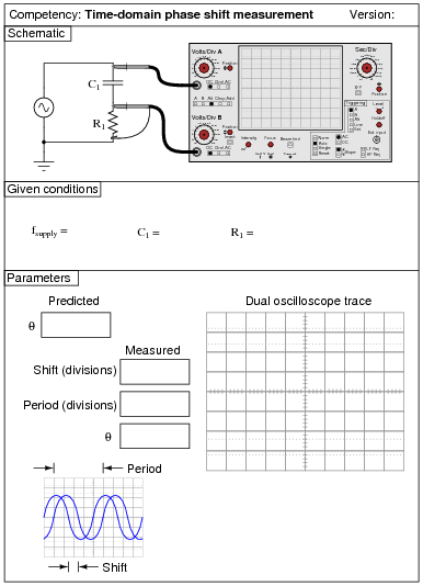
Use a sine-wave function generator for the AC voltage source. I recommend against using line-power AC because of strong harmonic frequencies which may be present (due to nonlinear loads operating on the same power circuit). Specify standard resistor and capacitor values.
I recommend using components that produce a phase shift of approximately 45 degrees within the low audio frequency range (less than 1 kHz). This allows most multimeters to be used for voltage measurement in conjunction with the oscilloscope.
One way for students to do this assessment is to have them predict what the sine waves will look like, based on circuit component values. They sketch the predicted waveforms on the grid provided before actually hooking up an oscilloscope, then the instructor assesses them based on the conformity of the real oscilloscope display to their prediction.
Question 29:
|
|
Notes:
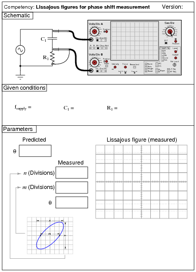
Use a sine-wave function generator for the AC voltage source. I recommend against using line-power AC because of strong harmonic frequencies which may be present (due to nonlinear loads operating on the same power circuit). Specify standard resistor and capacitor values.
I recommend using components that produce a phase shift of approximately 45 degrees within the low audio frequency range (less than 1 kHz). This allows most multimeters to be used for voltage measurement in conjunction with the oscilloscope.
Something to suggest that students do is use their oscilloscopes' ground position on the coupling switch, to help center the dot on the screen before they set up their Lissajous figures for phase shift measurement.
One way for students to do this assessment is to have them predict what the Lissajous figure will look like, based on circuit component values. They sketch the predicted Lissajous figure on the grid provided (working the math "backward" to arrive at n and m values before actually hooking up an oscilloscope), then the instructor assesses them based on the conformity of the real oscilloscope display to their prediction.
Question 30:
|
|
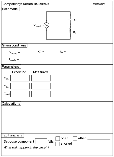
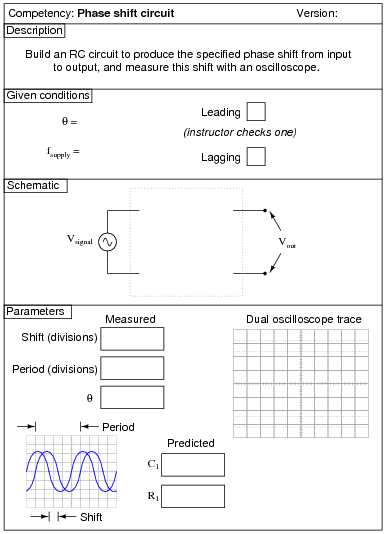
Notes:
Here, students must choose the right type of series RC circuit configuration to provide the requested phase shift. This, of course, also involves choosing proper values for C1 and R1, and being able to successfully measure phase shift with an oscilloscope.
I recommend selecting a phase shift angle (Q) somewhere between 15o and 75o. Angles too close to 90o will result in small output voltages that are difficult to measure through the noise.
An extension of this exercise is to incorporate troubleshooting questions. Whether using this exercise as a performance assessment or simply as a concept-building lab, you might want to follow up your students' results by asking them to predict the consequences of certain circuit faults.
Question 31:
|
|
Notes:
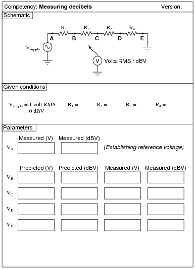
You will need an AC signal source of variable voltage, so that the reference voltage at test point A (VA) may be precisely adjusted to 1 volt RMS. The frequency of the signal source must be within the range of the voltmeter to measure, of course. You may use a sine-wave signal generator as the source, but a step-down transformer and series potentiometer works just as well! The purpose of this exercise is not how to calculate voltage divider outputs, but rather how to utilize a dB-reading meter to measure signal strength in decibels rather than volts AC.
Most high-quality digital multimeters will measure dBV in addition to AC volts RMS. Some have a "zero" or "relative" button which acts like the "tare" button on an electronic weigh scale. With such a meter, one may set 0 dB to reference at any measurable level of AC voltage. Of course, this means the meter will be measuring dB instead of dBV, since the reference point is made arbitrary with the press of the "relative" button. However, this is a very useful tool for electronic signal measurements, where source strength may be set to 0 dB and then losses measured directly in -dB (relative to the source) just as easily as normal voltage measurements.
Question 32:
|
|
Notes:
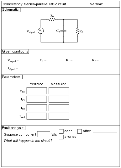
Use a sine-wave function generator for the AC voltage source. I recommend against using line-power AC because of strong harmonic frequencies which may be present (due to nonlinear loads operating on the same power circuit). Specify standard resistor and capacitor values.
If students are to use a multimeter to make their current and voltage measurements, be sure it is capable of accurate measurement at the circuit frequency! Inexpensive digital multimeters often experience difficulty measuring AC voltage and current toward the high end of the audio-frequency range.
An extension of this exercise is to incorporate troubleshooting questions. Whether using this exercise as a performance assessment or simply as a concept-building lab, you might want to follow up your students' results by asking them to predict the consequences of certain circuit faults.
Question 33:
|
|
Notes:
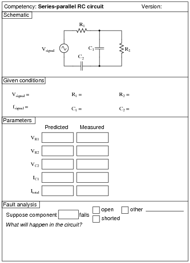
Use a sine-wave function generator for the AC voltage source. I recommend against using line-power AC because of strong harmonic frequencies which may be present (due to nonlinear loads operating on the same power circuit). Specify standard resistor and capacitor values.
If students are to use a multimeter to make their current and voltage measurements, be sure it is capable of accurate measurement at the circuit frequency! Inexpensive digital multimeters often experience difficulty measuring AC voltage and current toward the high end of the audio-frequency range.
An extension of this exercise is to incorporate troubleshooting questions. Whether using this exercise as a performance assessment or simply as a concept-building lab, you might want to follow up your students' results by asking them to predict the consequences of certain circuit faults.
Question 34:
|
|
Notes:
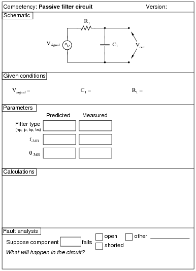
Use a sine-wave function generator for the AC voltage source. Specify standard resistor and capacitor values.
I recommend setting the function generator output for 1 volt, to make it easier for students to measure the point of "cutoff". You may set it at some other value, though, if you so choose (or let students set the value themselves when they test the circuit!).
I also recommend having students use an oscilloscope to measure AC voltage in a circuit such as this, because some digital multimeters have difficulty accurately measuring AC voltage much beyond line frequency range. I find it particularly helpful to set the oscilloscope to the "X-Y" mode so that it draws a thin line on the screen rather than sweeps across the screen to show an actual waveform. This makes it easier to measure peak-to-peak voltage.
An extension of this exercise is to incorporate troubleshooting questions. Whether using this exercise as a performance assessment or simply as a concept-building lab, you might want to follow up your students' results by asking them to predict the consequences of certain circuit faults.
Question 35:
|
|
Notes:
Use a sine-wave function generator for the AC voltage source. Specify standard resistor and capacitor values.
I recommend setting the function generator output for 1 volt, to make it easier for students to measure the point of "cutoff". You may set it at some other value, though, if you so choose (or let students set the value themselves when they test the circuit!).
I also recommend having students use an oscilloscope to measure AC voltage in a circuit such as this, because some digital multimeters have difficulty accurately measuring AC voltage much beyond line frequency range. I find it particularly helpful to set the oscilloscope to the "X-Y" mode so that it draws a thin line on the screen rather than sweeps across the screen to show an actual waveform. This makes it easier to measure peak-to-peak voltage.
An extension of this exercise is to incorporate troubleshooting questions. Whether using this exercise as a performance assessment or simply as a concept-building lab, you might want to follow up your students' results by asking them to predict the consequences of certain circuit faults.
Question 36:
|
|
Notes:
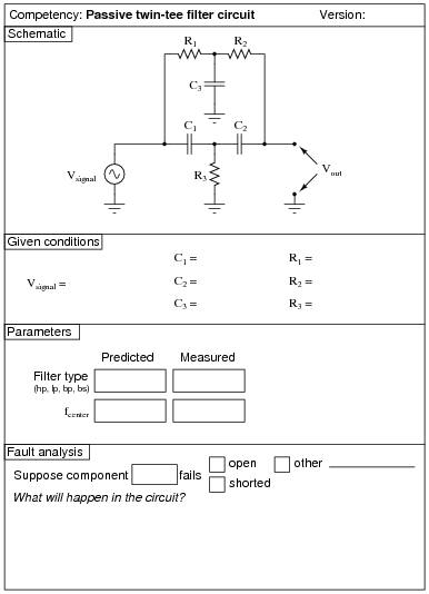
Use a sine-wave function generator for the AC voltage source. Specify components giving a notch frequency within the audio range:
|
I have had good success using the following values:
- �
- R1 = 10 kW
- �
- R2 = 10 kW
- �
- R3 = 5 kW (actually, two 10 kW resistors in parallel)
- �
- C1 = 0.001 mF
- �
- C2 = 0.001 mF
- �
- C3 = 0.002 mF (actually, two 0.001 mF capacitors in parallel)
These component values yield a theoretical notch frequency of 16.13 kHz (the very high end of audio range), with the actual measured notch frequency for my circuit (without considering component tolerances) being 15.92 kHz.
I recommend setting the function generator output for 1 volt, to make it easier for students to measure the point of "cutoff". You may set it at some other value, though, if you so choose (or let students set the value themselves when they test the circuit!).
I also recommend having students use an oscilloscope to measure AC voltage in a circuit such as this, because some digital multimeters have difficulty accurately measuring AC voltage much beyond line frequency range. I find it particularly helpful to set the oscilloscope to the "X-Y" mode so that it draws a thin line on the screen rather than sweeps across the screen to show an actual waveform. This makes it easier to measure peak-to-peak voltage.
Question 37:
|
|
Notes:
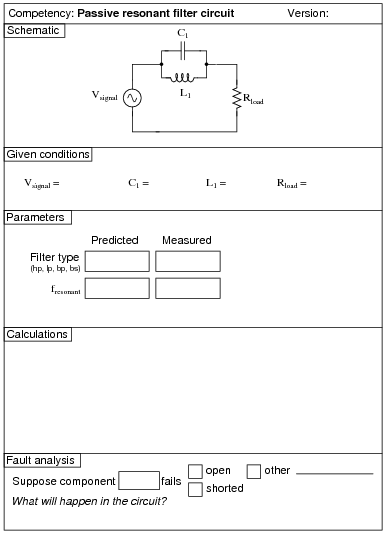
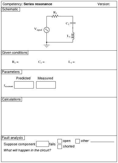
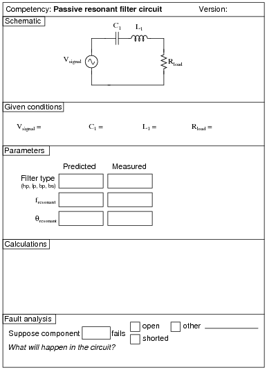
Use a sine-wave function generator for the AC voltage source. Specify standard resistor, capacitor, and inductor values. I have used a small 100 mH inductor, a 0.033 mF capacitor, and 100 W resistor with good success. In any case I recommend keeping the resonant frequency within the mid-audio range (1 kHz to 10 kHz) to avoid problems with low inductor Q (frequency too low) and stray capacitance and inductance issues (frequency too high).
Question 38:
|
|
Notes:
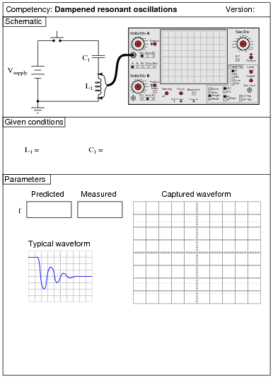
A digital oscilloscope capable of "capturing" the dampened oscillations will be necessary for this exercise. It will be very challenging to measuring the oscillation frequency using an analog (phosphor) oscilloscope!
An extension of this exercise is to incorporate troubleshooting questions. Whether using this exercise as a performance assessment or simply as a concept-building lab, you might want to follow up your students' results by asking them to predict the consequences of certain circuit faults.
Question 39:
|
|
Notes:
Use a sine-wave function generator for the AC voltage source. Specify standard resistor, capacitor, and inductor values. I have used a small 100 mH inductor, a 0.033 mF capacitor, and 100 W resistor with good success. In any case I recommend keeping the resonant frequency within the mid-audio range (1 kHz to 10 kHz) to avoid problems with low inductor Q (frequency too low) and stray capacitance and inductance issues (frequency too high).
I also recommend having students use an oscilloscope to measure AC voltage in a circuit such as this, because some digital multimeters have difficulty accurately measuring AC voltage much beyond line frequency range. I find it particularly helpful to set the oscilloscope to the "X-Y" mode so that it draws a thin line on the screen rather than sweeps across the screen to show an actual waveform. This makes it easier to measure peak-to-peak voltage.
An extension of this exercise is to incorporate troubleshooting questions. Whether using this exercise as a performance assessment or simply as a concept-building lab, you might want to follow up your students' results by asking them to predict the consequences of certain circuit faults.
Question 40:
|
|
Notes:
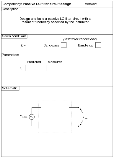
Use a sine-wave function generator for the AC voltage source. Specify a resonant frequency within the audio range.
This exercise assumes access to a variety of capacitor and/or inductor sizes, so the student may make series-parallel networks to achieve the necessary values of L and/or C. It would be wise for you (the instructor) to check your students' component kits for L and C values prior to choosing resonant frequencies for them to try to achieve.
I also recommend having students use an oscilloscope to measure AC voltage in a circuit such as this, because some digital multimeters have difficulty accurately measuring AC voltage much beyond line frequency range. I find it particularly helpful to set the oscilloscope to the "X-Y" mode so that it draws a thin line on the screen rather than sweeps across the screen to show an actual waveform. This makes it easier to measure peak-to-peak voltage.
Question 41:

|
|
Notes:
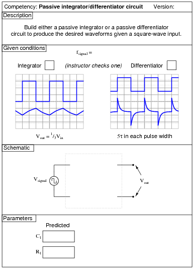
Here, students must calculate values for C1 and R1 that will produce the Vout waveshape specified in the "Given conditions" oscilloscope plot. The input signal, of course, is a square wave. Students must calculate the time constant of the circuit (t) such that the pulse fully decays within the pulse width (half-period) of the square wave. With 5 t being the accepted standard for full charge/discharge of a time-constant circuit, this is an easy calculation.
There are many different combinations of values for C1 and R1 possible for any given square-wave signal frequencies. The purpose of this exercise is for students to be able to predict and select practical component values from their parts kits.
An extension of this exercise is to incorporate troubleshooting questions. Whether using this exercise as a performance assessment or simply as a concept-building lab, you might want to follow up your students' results by asking them to predict the consequences of certain circuit faults.
Question 42:
|
|
Notes:
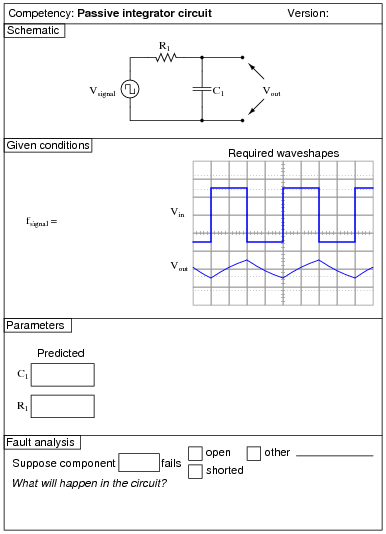
Here, students must calculate values for C1 and R1 that will produce the Vout waveshape specified in the "Given conditions" oscilloscope plot. The input signal, of course, is a square wave. Students should be able to show mathematically why the time constant of the integrator (t) must be 69.3% of the waveform's half-period. Instructors, note: the calculations for this circuit, with Vout = 1/3Vin, are exactly the same as for a 555 timer circuit, because 555 timers also cycle their capacitors' voltages at peak-to-peak values equal to one-third of the supply voltage.
There are many different combinations of values for C1 and R1 possible for any given square-wave signal frequencies. The purpose of this exercise is for students to be able to predict and select practical component values from their parts kits.
An extension of this exercise is to incorporate troubleshooting questions. Whether using this exercise as a performance assessment or simply as a concept-building lab, you might want to follow up your students' results by asking them to predict the consequences of certain circuit faults.
Question 43:
|
|
Notes:
Here, students must calculate values for C1 and R1 that will produce the Vout waveshape specified in the "Given conditions" oscilloscope plot. The input signal, of course, is a square wave.
If the chosen circuit is a differentiator, students must calculate the time constant of the circuit (t) such that the pulse fully decays within the pulse width (half-period) of the square wave. With 5 t being the accepted standard for full charge/discharge of a time-constant circuit, this is an easy calculation.
If the chosen circuit is an integrator, students should be able to show mathematically why the time constant of the integrator (t) must be 69.3% of the waveform's half-period. Instructors, note: the calculations for this circuit, with Vout = 1/3Vin, are exactly the same as for a 555 timer circuit, because 555 timers also cycle their capacitors' voltages at peak-to-peak values equal to one-third of the supply voltage.
There are many different combinations of values for C1 and R1 possible for any given square-wave signal frequencies. The purpose of this exercise is for students to be able to predict and select practical component values from their parts kits.
An extension of this exercise is to incorporate troubleshooting questions. Whether using this exercise as a performance assessment or simply as a concept-building lab, you might want to follow up your students' results by asking them to predict the consequences of certain circuit faults.
Question 44:
|
|
Notes:
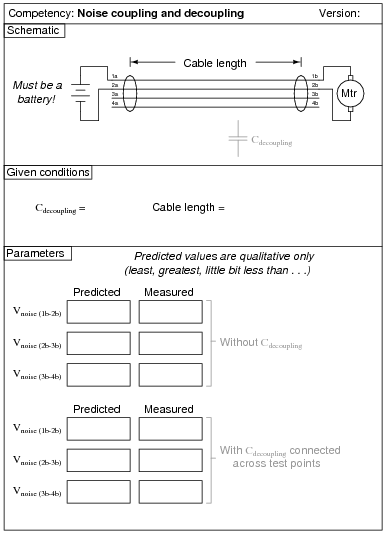
The longer the cable, the better the coupling between the motor conductors and the other conductors. I have found that this exercise is practical with just a few feet of four-wire telephone cable.
It is very important to use a battery for this exercise, and not an AC-DC power supply. The filter capacitors in an AC-DC power supply naturally decouple the motor's noise voltage, making it difficult to measure any at all!
Noise voltage should be measured with an oscilloscope set to AC input coupling, and recorded as peak-to-peak volts.
Question 45:
|
|
Notes:
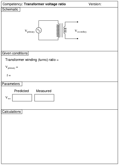
You may use an audio frequency impedance matching (1000:8 ohms) transformer or a step-down power transformer for this exercise. In either case, students need to know or figure out the turns ratio before proceeding with the experiment. If you are using an audio transformer, use a sine-wave signal generator for the voltage source, but avoid frequencies below 1kHz. If you are using a power transformer, use a Variac to provide adjustable primary voltage.
An extension of this exercise is to incorporate troubleshooting questions. Whether using this exercise as a performance assessment or simply as a concept-building lab, you might want to follow up your students' results by asking them to predict the consequences of certain circuit faults.
Question 46:
|
|
Notes:
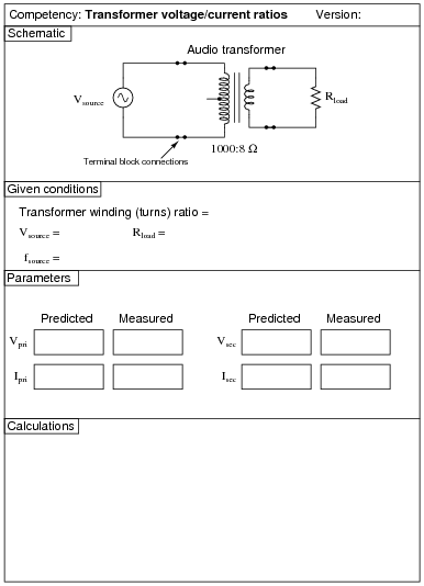
Use an audio frequency impedance matching (1000:8 ohms) transformer for this exercise, using a load resistance great enough not to overload the signal generator powering it. I recommend using a 100 kW resistor for the load. With the audio transformer's impedance ratio, this should appear as an 800 W load to the signal generator. Avoid frequencies below 1 kHz - power line frequency is much too low for this type of transformer.
An extension of this exercise is to incorporate troubleshooting questions. Whether using this exercise as a performance assessment or simply as a concept-building lab, you might want to follow up your students' results by asking them to predict the consequences of certain circuit faults.
Question 47:
|
|
Notes:
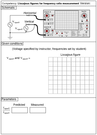
Lissajous figures are very informative if one understands how to interpret them. The purpose of this exercise is for students to learn exactly how to do that, in the context of measuring frequency (ratios). Please use sinusoidal AC sources (variable-frequency signal generators) for this exercise.
The instructor will determine the voltage of the two sources (set the same), and also will graphically specify the Lissajous figure by drawing the desired figure on the oscilloscope screen illustration. The student's task is to figure out what frequency ratio will generate this pattern on the oscilloscope screen, and set the signal generators to that ratio (one set to 1 kHz, the other to the appropriate frequency). This works best if the student can only see the signal generator controls and frequency counter displays, and only the instructor can see the oscilloscope display.
Here are some sample Lissajous figures to draw for your students to duplicate:

|
|
Question 48:
|
|
Notes:
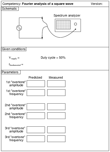
By the word overtone, I imply the musical concept: the successive harmonics appearing in this particular non-sinusoidal waveform. If I were to say "1st harmonic," "2nd harmonic," and "3rd harmonic," this would specifically refer to ffundamental, 2ffundamental, and 3ffundamental, respectively. The first of these would be given, the second nonexistent in a square wave with 50% duty cycle, leaving only the third as something to actually predict and measure. By övertones," I mean the first, second, and third frequencies greater than the fundamental frequency found in a square wave, that happen to be harmonics of the fundamental.
If you lack a spectrum analyzer in your lab, fear not! There are free software packages in existence allowing you to use the audio input of a personal computer's sound card as a (limited) spectrum analyzer and oscilloscope! You may find some of these packages by searching on the Internet. One that I've used (2002) successfully in my own class is called WinScope.
Question 49:
|
|
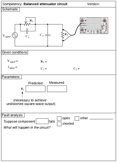
Note: this circuit works on the same basic principle as the compensation adjustment on high-quality oscilloscope probes, except that here the resistor is variable and not the capacitor.
Notes:
Use a square-wave function generator for the AC voltage source. I have built this circuit using resistances of approximately 4.7 kW and capacitances of approximately 0.1 mF, and achieved good results with a square-wave (fundamental) frequency of about 300 Hz. Of course, the R1 resistance calculation is more challenging if the two capacitor values are unequal!
Incidentally, this circuit may be used to comparatively measure reactive components such as capacitors and inductors, since the square wave signal will be faithfully reproduced only when the [(R1)/(R2)] ratio equals the [(XC1)/(XC2)] or [(XL1)/(XL2)] ratio. To be honest, the idea was not mine. I found it in an old book, the Electronics Manual for Radio Engineers, by Vin Zeluff and John Markus, first edition (1949), page 427. Apparently, the inventor of this ingenious impedance measurement technique was an employee of Allen B. DuMont Lab., Inc. named Peter S. Christaldi, who obtained a patent for the technique on October 15, 1946 (patent number 2,409,419 for those who are interested).
An extension of this exercise is to incorporate troubleshooting questions. Whether using this exercise as a performance assessment or simply as a concept-building lab, you might want to follow up your students' results by asking them to predict the consequences of certain circuit faults.
Question 50:
|
|
Notes:
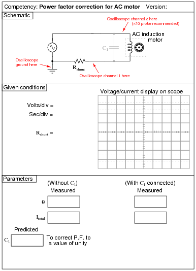
When presenting this as a performance assessment for a group of students, you will need to show the voltage/current waveforms as part of the "given" conditions. A good way to do this is to use a PC-based oscilloscope to measure the waveforms, and then display the image using a video projector.
I have found that small synchronous AC motors such as those used in clock mechanisms and in some appliances (microwave oven carousels, for example) will run satisfactorily at 24 volts AC. Small shaded-pole motors such as those used in household bathroom fans and household appliances (microwave oven cooling fans, for example) may be operated in a relatively safe manner from low-voltage AC power by stepping the voltage up through a power transformer connected directly to the motor. Use a ßtep down" power transformer operating in reverse (as a step-up unit), with the higher voltage wires connected and taped to the motor so that the only "loose" wire connections are on the low-voltage side. Here is a power supply circuit I recommend for the task:
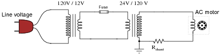
|
|
This circuit ensures the motor only receives about 60 volts, reducing shock hazard somewhat and allowing the use of capacitors rated for 100 volts (a common mylar capacitor rating). The smaller the motor, the less capacitance will be required to correct for power factor. Remind your students that the capacitors used in this exercise must be non-polarized, since they must operate on AC and not DC!
A shunt resistor value of 1 ohm is recommended, but not absolutely required. You just need a low-value resistor that will provide a ready point of measurement for current (with the oscilloscope) without imposing too much series resistance in the motor circuit.
Question 51:
|
|
Notes:
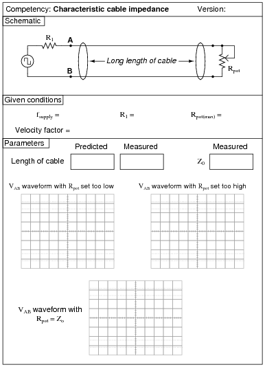
This is a very simple yet effective exercise in demonstrating the effects of reflections in cables where the termination resistance (Rpot) is unequal to the cable's characteristic impedance (Z0). It is also an easy way to measure Z0, by adjusting Rpot until a match is shown by an undistorted square-wave between points A and B.
I've used ordinary "zip cord" type speaker wire for this experiment. You can also use household extension cords or lengths of coaxial cable if you prefer. Coax has the benefit of already being rated for a specified impedance, unlike the other cable types listed. A length of 100 feet works well to produce time delays easily measurable with inexpensive oscilloscopes.
The purpose of resistor R1 is to ßwamp" the square-wave signal generator's own Thévenin impedance, so it does not become a significant factor in the system. The maximum resistance of rheostat Rpot is really not that critical. I've easily achieved a match on speaker cable with Z0 � 136 W using a 10 kW potentiometer for Rpot. A 1 kW potentiometer would probably be best.
If you wish your students to be able to accurately predict the length of their cable from the waveshapes displayed by the oscilloscope, you need to determine the cable's velocity factor beforehand, and write that value in the "Given conditions" section. Otherwise, you could have students infer velocity factor from cable length and oscilloscope measurements.