Performance-based assessments for DC circuit competencies
Question 1:
| (Template) |
|
|
Notes:
Any relevant notes for the assessment activity go here.
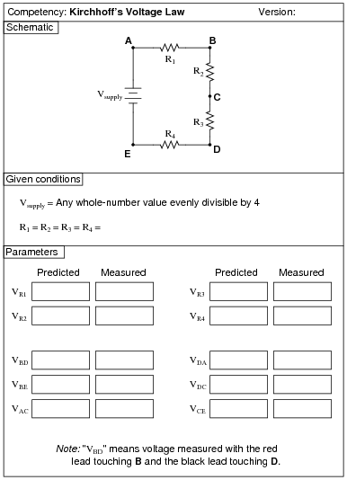
Question 2:
|
|
Notes:
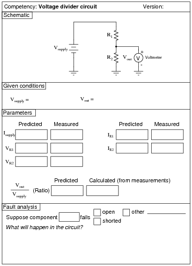
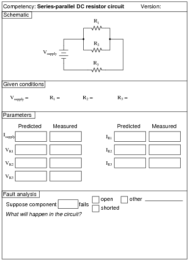
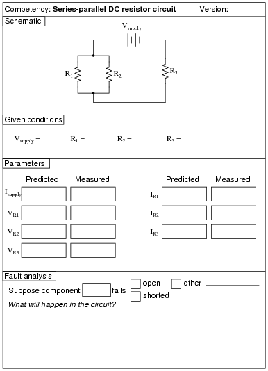
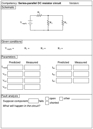
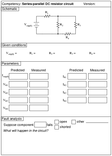
Use a variable-voltage, regulated power supply to supply any amount of DC voltage below 30 volts. Students will have to choose resistor values appropriate to the task.
An extension of this exercise is to incorporate troubleshooting questions. Whether using this exercise as a performance assessment or simply as a concept-building lab, you might want to follow up your students' results by asking them to predict the consequences of certain circuit faults.
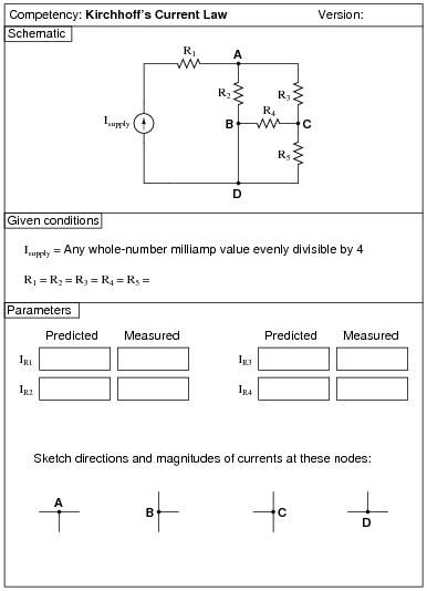
Question 3:
|
|
Notes:
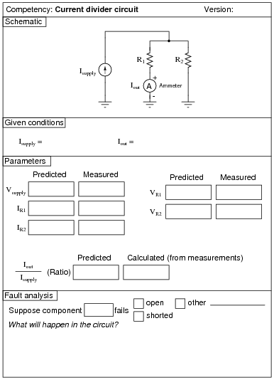
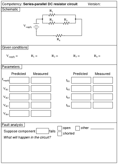
Use a variable-current, regulated power supply to supply any amount of DC current below a few milliamps. Students will have to choose resistor values appropriate to the task. I recommend low-value resistors so as to keep the voltage drop (and power dissipation!) low.
An extension of this exercise is to incorporate troubleshooting questions. Whether using this exercise as a performance assessment or simply as a concept-building lab, you might want to follow up your students' results by asking them to predict the consequences of certain circuit faults.
Question 4:
|
|
Notes:
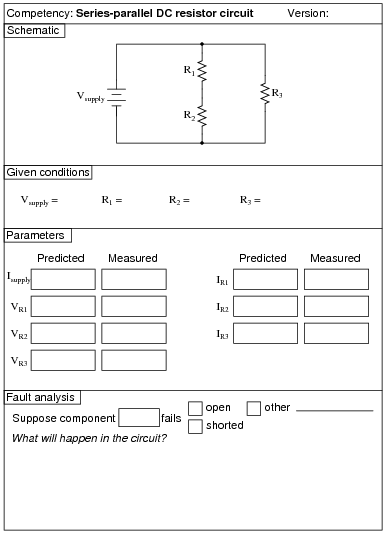
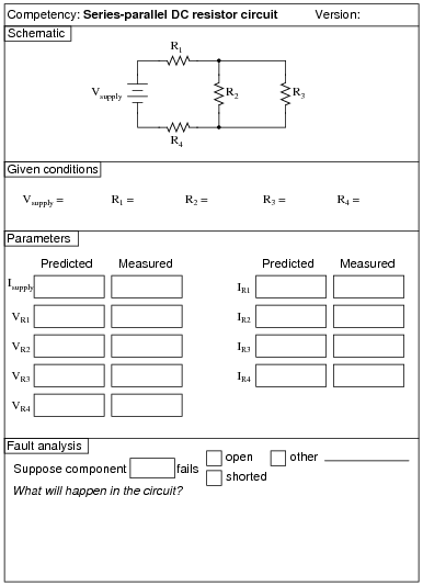
Use a variable-voltage, regulated power supply to supply any amount of DC voltage below 30 volts. Specify standard resistor values, all between 1 kW and 100 kW (1k5, 2k2, 2k7, 3k3, 4k7, 5k1, 6k8, 10k, 22k, 33k, 39k 47k, 68k, etc.).
An extension of this exercise is to incorporate troubleshooting questions. Whether using this exercise as a performance assessment or simply as a concept-building lab, you might want to follow up your students' results by asking them to predict the consequences of certain circuit faults.
Question 5:
|
|
Notes:
Use a variable-voltage, regulated power supply to supply any amount of DC voltage below 30 volts. Specify standard resistor values, all between 1 kW and 100 kW (1k5, 2k2, 2k7, 3k3, 4k7, 5k1, 6k8, 10k, 22k, 33k, 39k 47k, 68k, etc.).
An extension of this exercise is to incorporate troubleshooting questions. Whether using this exercise as a performance assessment or simply as a concept-building lab, you might want to follow up your students' results by asking them to predict the consequences of certain circuit faults.
Question 6:
|
|
Notes:
Use a variable-voltage, regulated power supply to supply any amount of DC voltage below 30 volts. Specify standard resistor values, all between 1 kW and 100 kW (1k5, 2k2, 2k7, 3k3, 4k7, 5k1, 6k8, 10k, 22k, 33k, 39k 47k, 68k, etc.).
An extension of this exercise is to incorporate troubleshooting questions. Whether using this exercise as a performance assessment or simply as a concept-building lab, you might want to follow up your students' results by asking them to predict the consequences of certain circuit faults.
Question 7:
|
|
Notes:
Use a variable-voltage, regulated power supply to supply any amount of DC voltage below 30 volts. Specify standard resistor values, all between 1 kW and 100 kW (1k5, 2k2, 2k7, 3k3, 4k7, 5k1, 6k8, 10k, 22k, 33k, 39k 47k, 68k, etc.).
An extension of this exercise is to incorporate troubleshooting questions. Whether using this exercise as a performance assessment or simply as a concept-building lab, you might want to follow up your students' results by asking them to predict the consequences of certain circuit faults.
Question 8:
|
|
Notes:
Use a variable-voltage, regulated power supply to supply any amount of DC voltage below 30 volts. Specify standard resistor values, all between 1 kW and 100 kW (1k5, 2k2, 2k7, 3k3, 4k7, 5k1, 6k8, 8k2, 10k, 22k, 33k, 39k 47k, 68k, 82k, etc.).
An extension of this exercise is to incorporate troubleshooting questions. Whether using this exercise as a performance assessment or simply as a concept-building lab, you might want to follow up your students' results by asking them to predict the consequences of certain circuit faults.
Question 9:
|
|
Notes:
Use a variable-voltage, regulated power supply to supply any amount of DC voltage below 30 volts. Specify standard resistor values, all between 1 kW and 100 kW (1k5, 2k2, 2k7, 3k3, 4k7, 5k1, 6k8, 8k2, 10k, 22k, 33k, 39k 47k, 68k, 82k, etc.).
An extension of this exercise is to incorporate troubleshooting questions. Whether using this exercise as a performance assessment or simply as a concept-building lab, you might want to follow up your students' results by asking them to predict the consequences of certain circuit faults.
Question 10:
|
|
Notes:
Use a variable-voltage, regulated power supply to supply any amount of DC voltage below 30 volts. Specify standard resistor values, all between 1 kW and 100 kW (1k5, 2k2, 2k7, 3k3, 4k7, 5k1, 6k8, 8k2, 10k, 22k, 33k, 39k 47k, 68k, 82k, etc.).
An extension of this exercise is to incorporate troubleshooting questions. Whether using this exercise as a performance assessment or simply as a concept-building lab, you might want to follow up your students' results by asking them to predict the consequences of certain circuit faults.
Question 11:
|
|
Notes:
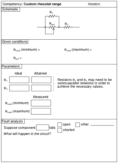
Be sure to remind your students that resistances R1 and R2 may need to be series-parallel networks in themselves, to achieve the necessary values. An alternative you may wish to permit is the use of 10-turn (precision) potentiometers connected as rheostats for R1 and R2. This way the circuit's minimum and maximum values may be precisely calibrated. The main potentiometer, Rpot1, should be a 3/4 turn unit, to allow fast checking of minimum and maximum total resistance, and it should be some common value such as 1 kW or 10 kW.
Question 12:
|
|
Notes:
Students need not measure potentiometer shaft angles in order to do this exercise. Rather, all they need to do is measure resistance between the wiper and the two outer terminals to set the potentiometer to a position where it will produce the specified division of voltage.
An extension of this exercise is to incorporate troubleshooting questions. Whether using this exercise as a performance assessment or simply as a concept-building lab, you might want to follow up your students' results by asking them to predict the consequences of certain circuit faults.
Question 13:
|
|
Notes:
An extension of this exercise is to incorporate troubleshooting questions. Whether using this exercise as a performance assessment or simply as a concept-building lab, you might want to follow up your students' results by asking them to predict the consequences of certain circuit faults.
Question 14:
|
|
Notes:
I recommend students use a normal regulated (voltage) power supply, adjusting the output voltage until the output current is at 4 mA. 1 kW resistors work well for this circuit, requiring only 6.4 volts from the power supply to achieve 4 mA total current.
An extension of this exercise is to incorporate troubleshooting questions. Whether using this exercise as a performance assessment or simply as a concept-building lab, you might want to follow up your students' results by asking them to predict the consequences of certain circuit faults.
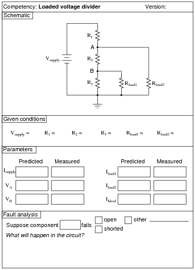
Question 15:
|
|
Notes:
Use a variable-voltage, regulated power supply to supply any amount of DC voltage below 30 volts. Specify standard resistor values, all between 1 kW and 100 kW (1k5, 2k2, 2k7, 3k3, 4k7, 5k1, 6k8, 8k2, 10k, 22k, 33k, 39k 47k, 68k, 82k, etc.).
I have used this circuit as both a "quick" lab exercise and a troubleshooting exercise, using values of 10 kW for R1, R2, and R3; 15 kW for R(load1); 22 kW for R(load2); and 6 volts for the power supply. Of course, these component values are not critical, but they do provide easy-to measure voltages and currents without incurring excessive impedances that would cause significant voltmeter loading problems.
An extension of this exercise is to incorporate troubleshooting questions. Whether using this exercise as a performance assessment or simply as a concept-building lab, you might want to follow up your students' results by asking them to predict the consequences of certain circuit faults.
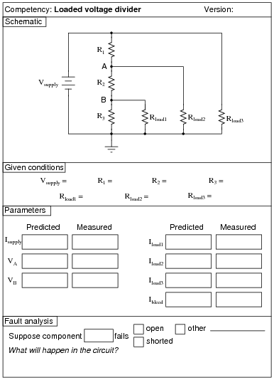
Question 16:
|
|
Notes:
Use a variable-voltage, regulated power supply to supply any amount of DC voltage below 30 volts. Specify standard resistor values, all between 1 kW and 100 kW (1k5, 2k2, 2k7, 3k3, 4k7, 5k1, 6k8, 10k, 22k, 33k, 39k 47k, 68k, etc.).
An extension of this exercise is to incorporate troubleshooting questions. Whether using this exercise as a performance assessment or simply as a concept-building lab, you might want to follow up your students' results by asking them to predict the consequences of certain circuit faults.
Question 17:
|
|
Notes:
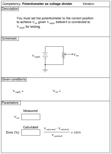
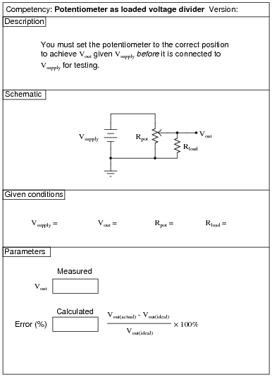
Students need not measure potentiometer shaft angles in order to do this exercise. Rather, all they need to do is measure resistance between the wiper and the two outer terminals to set the potentiometer to a position where it will produce the specified division of voltage.
Rpot refers to the potentiometer's nominal full-range value (for example, 1 kW or 5 kW), and not to its particular setting. The setting is what the student must figure out to achieve Vout.
An extension of this exercise is to incorporate troubleshooting questions. Whether using this exercise as a performance assessment or simply as a concept-building lab, you might want to follow up your students' results by asking them to predict the consequences of certain circuit faults.
Question 18:
|
|
Notes:
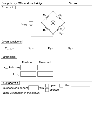
Use a variable-voltage, regulated power supply to supply any amount of DC voltage below 30 volts. Specify standard resistor values, all between 1 kW and 100 kW (1k5, 2k2, 2k7, 3k3, 4k7, 5k1, 6k8, 10k, 22k, 33k, 39k 47k, 68k, etc.), and be sure to specify a potentiometer value in excess of the amount required to balance the bridge.
An extension of this exercise is to incorporate troubleshooting questions. Whether using this exercise as a performance assessment or simply as a concept-building lab, you might want to follow up your students' results by asking them to predict the consequences of certain circuit faults.
Question 19:
|
|
Notes:
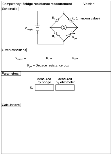
Use a variable-voltage, regulated power supply to supply any amount of DC voltage below 30 volts. Use precision resistors for R1 and R2, and use any standard resistor value for Rx between 1 kW and 100 kW.
An extension of this exercise is to incorporate troubleshooting questions. Whether using this exercise as a performance assessment or simply as a concept-building lab, you might want to follow up your students' results by asking them to predict the consequences of certain circuit faults.
Question 20:
|
|
Notes:
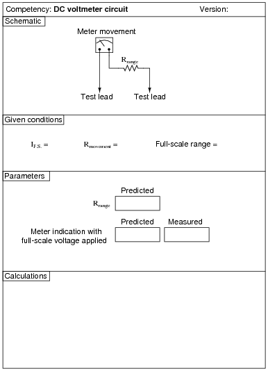
Students may use potentiometers in their range resistance networks to achieve precise values. However, they are not allowed to adjust those potentiometers after connecting them to the meter movement - they must set their potentiometer(s) during the "prediction" step of the assessment before the circuit is completely built.
An extension of this exercise is to incorporate troubleshooting questions. Whether using this exercise as a performance assessment or simply as a concept-building lab, you might want to follow up your students' results by asking them to predict the consequences of certain circuit faults.
Question 21:
|
|
Notes:
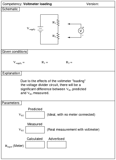
Be sure to specify resistor values for the voltage divider that will show a marked impact when measured with the type of voltmeter you expect your students to use. If you size the resistors for a modest impact measured with an analog voltmeter (20,000 W/Volt), your students may not see much of an impact when using a modern digital voltmeter (Zin > 10 MW).
New students often have a difficult time grasping the main idea of this activity, due to the assumption of the voltmeter's indication always being taken as true. The purpose of this activity is to shatter that assumption: to teach students that electrical measurements are never truly passive - rather, they invariably impact the circuit being measured in some way. Usually, the impact is so small it may be safely ignored. Here, due to the large resistor values used in the divider circuit, the impact of voltmeter usage on the circuit is non-trivial.
Another aspect of this activity that escapes some students' attention is that the circuit must be analyzed twice: once with the meter connected and once without. The point here is that the meter becomes a component of the circuit when it is connected across R2, and thus changes all the voltages and currents.
Question 22:
|
|
Notes:
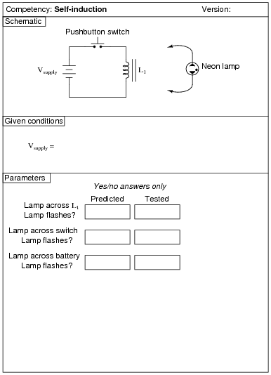
Students may either use ready-made inductors for this experiment (the larger the value, the more impressive the light flash!) or inductors of their own making (using old solenoid valve coils, or hand-wound coils around steel bolts). Power transformer primary windings also work well for this.
Question 23:

|
|
Notes:
You will need an inductance meter in your lab to do this exercise. If you don't have one, you should get one right away!
Question 24:
|
|
Notes:
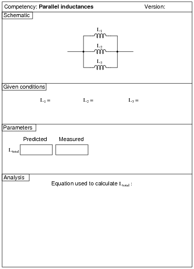
You will need an inductance meter in your lab to do this exercise. If you don't have one, you should get one right away!
Question 25:
|
|
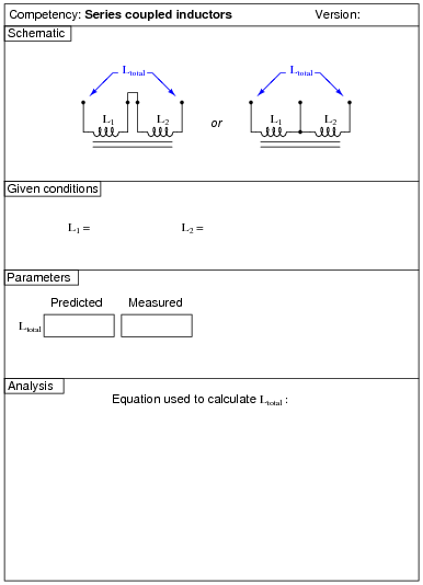
You might be surprised to find that Ltotal � L1 + L2. This is due to the mutual inductance between inductors L1 and L2.
Notes:
In case students don't have access to a pair of inductors on a common core, they may either make their own by winding wire around a long ferromagnetic core, or use a center-tapped inductor (or transformer winding). The latter solution is probably the easiest:

|
|
Inexpensive audio output transformers (with center-tapped 1000 W primary windings) work very well for this. Your students' parts kits should contain at least one of these transformers anyway if they are to do audio coupling experiments later.
You will need an inductance meter in your lab to do this exercise. If you don't have one, you should get one right away!
Question 26:
|
|
Notes:
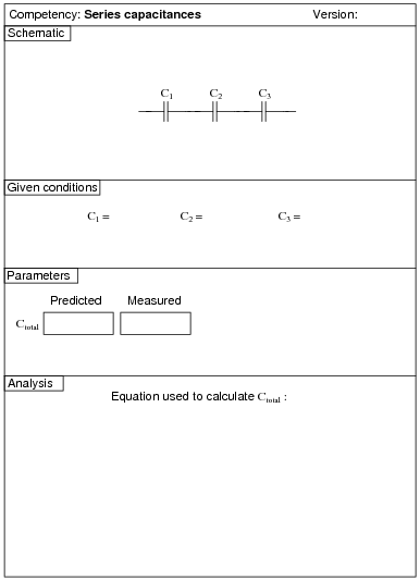
Many modern digital multimeters come equipped with capacitance measurement built-in. If your students do not have these meters, you will either need to provide one for them to use, or provide an LCR meter. If you don't have either one of these instruments, you should get one right away!
Question 27:
|
|
Notes:
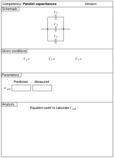
Many modern digital multimeters come equipped with capacitance measurement built-in. If your students do not have these meters, you will either need to provide one for them to use, or provide an LCR meter. If you don't have either one of these instruments, you should get one right away!
Question 28:
|
|
Notes:
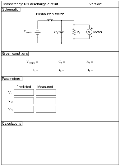
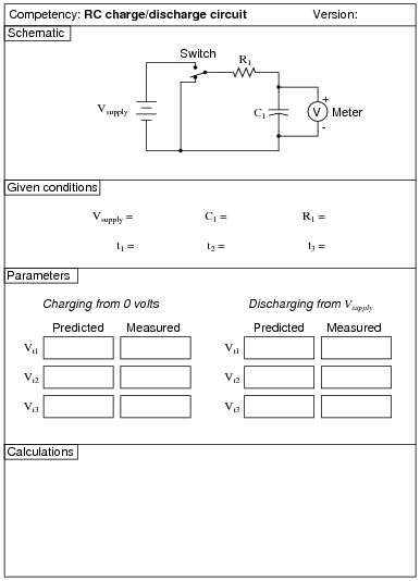
I recommend choosing resistor and capacitor values that yield time constants in the range that may be accurately tracked with a stopwatch. I also recommend using resistor values significantly less than the voltmeter's input impedance, so that voltmeter loading does not significantly contribute to the decay rate.
Good time values to use (t1, t2, t3) would be in the range of 5, 10, and 15 seconds, respectively.
An extension of this exercise is to incorporate troubleshooting questions. Whether using this exercise as a performance assessment or simply as a concept-building lab, you might want to follow up your students' results by asking them to predict the consequences of certain circuit faults.
Question 29:
|
|
Notes:
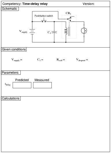
Two very important "given" parameters are the relay coil resistance (Rcoil) and the relay dropout voltage (Vdropout). These are best determined experimentally.
Many students fail to grasp the purpose of this exercise until it is explained. The idea here is to predict when the relay will "drop out" after the switch is opened. This means solving for t in the time-constant (decay) equation given the initial capacitor voltage, time constant (t), and the capacitor voltage at time t. Because this involves the use of logarithms, students may be perplexed until given assistance.
An extension of this exercise is to incorporate troubleshooting questions. Whether using this exercise as a performance assessment or simply as a concept-building lab, you might want to follow up your students' results by asking them to predict the consequences of certain circuit faults.
Question 30:
|
|
Notes:
I recommend choosing resistor and capacitor values that yield time constants in the range that may be accurately tracked with a stopwatch. I also recommend using resistor values significantly less than the voltmeter's input impedance, so that voltmeter loading does not significantly contribute to the decay rate.
Good time values to use (t1, t2, t3) would be in the range of 5, 10, and 15 seconds, respectively.
An extension of this exercise is to incorporate troubleshooting questions. Whether using this exercise as a performance assessment or simply as a concept-building lab, you might want to follow up your students' results by asking them to predict the consequences of certain circuit faults.
Question 31:
|
|
Notes:
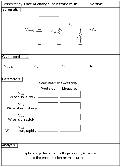
I recommend a supply voltage of 12 volts, a potentiometer value of 10 kW, a capacitor value of 0.1 mF, and a loading resistor (R1) of 1 MW. Use a DMM so as to not load the circuit any more than necessary. If you wish to choose different capacitor/resistor values, I strongly suggest choosing them such that the time constant (t) of the circuit significantly faster than 1 second.
An extension of this exercise is to incorporate troubleshooting questions. Whether using this exercise as a performance assessment or simply as a concept-building lab, you might want to follow up your students' results by asking them to predict the consequences of certain circuit faults.