Performance-based assessments for basic electricity competencies
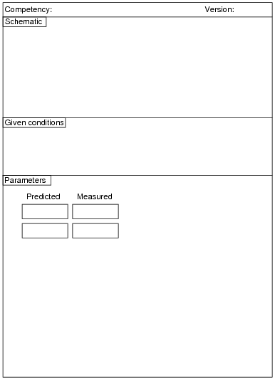
Question 1:
| (Template) |
|
|
Notes:
Any relevant notes for the assessment activity go here.
Question 2:

|
|
Notes:
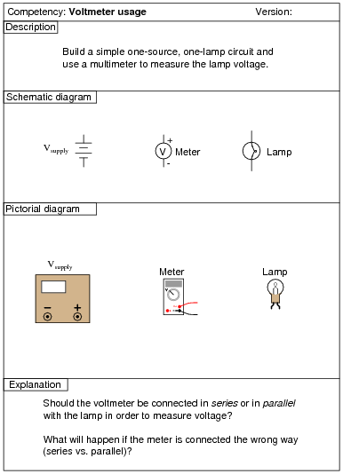
The purpose of this exercise is to make absolutely sure students can safely measure voltage with a multimeter.
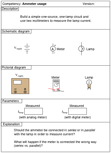
Question 3:
|
|
IMPORTANT NOTE: do not actually try to connect the ammeter improperly in the circuit, as the meter may be damaged in the process!
Notes:
The purpose of this exercise is to make absolutely sure students can safely measure current with a multimeter.
Question 4:
|
|
Notes:
Use a variable-voltage, regulated power supply to supply a suitable DC voltage for the incandescent lamp.
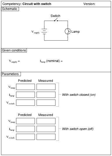
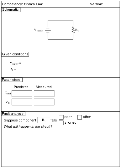
Question 5:
|
|
Notes:
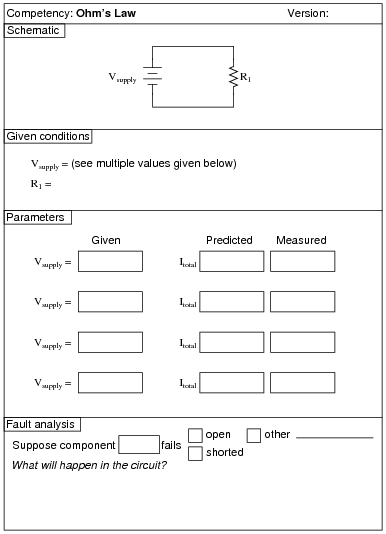
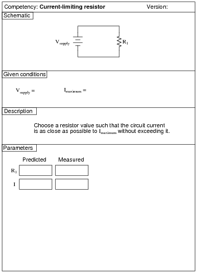
Use a variable-voltage, regulated power supply to supply any amount of DC voltage below 30 volts. Specify a standard resistor value, somewhere between 1 kW and 100 kW (1k5, 2k2, 2k7, 3k3, 4k7, 5k1, 6k8, 10k, 22k, 33k, 39k 47k, 68k, etc.).
If using this question as a lab exercise rather than an assessment, I recommend specifying a voltage that is standard for batteries, so students don't necessarily have to have an adjustable power supply available to do this lab.
For example, specify Vsupply as 6 volts and R1 as 33 kW. The resulting current is sufficient to provide a nice, strong needle deflection on most cheap analog ammeters, too!
Question 6:
|
|
Notes:
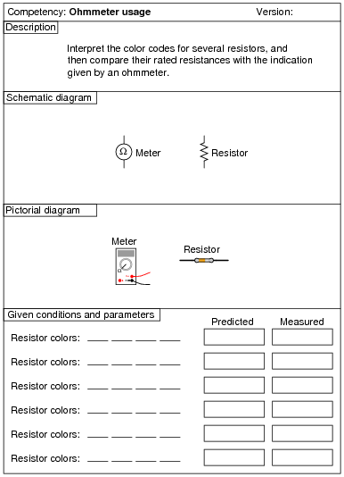
The purpose of this exercise is to make absolutely sure students can accurately measure resistance with a multimeter, and also that they can interpret resistor color codes. Select resistors that span a wide range, from less than 10 ohms to millions of ohms.
I recommend the following resistor color codes for students to try (all 5% tolerance):
- �
- Blk, Brn, Grn, Gld
- �
- Brn, Red, Brn, Gld
- �
- Blu, Gry, Blk, Gld
- �
- Red, Red, Org, Gld
- �
- Brn, Grn, Yel, Gld
- �
- Org, Org, Red, Gld
A good extension of this assessment is to have students demonstrate competency using both digital and analog multimeters!
Question 7:
|
|
Notes:
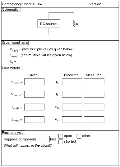
Use a variable-voltage, regulated power supply to supply any amount of DC voltage below 30 volts. Specify a standard resistor value, somewhere between 1 kW and 100 kW (1k5, 2k2, 2k7, 3k3, 4k7, 5k1, 6k8, 10k, 22k, 33k, 39k 47k, 68k, etc.).
An interesting "twist" on this exercise is to specify the value of resistor R1 in colors. For example: Red, Vio, Red, Gld instead of 2.7 kW.
Question 8:
|
|
Notes:
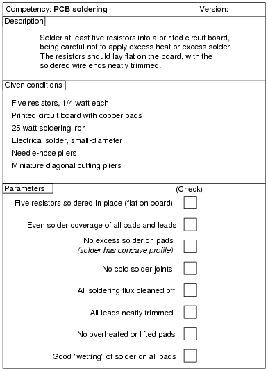
The purpose of this exercise is to ensure students can make good solder joints on a printed circuit board.
Question 9:
|
|
Notes:
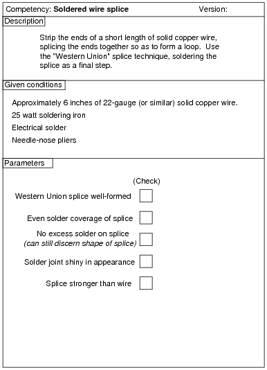
The purpose of this exercise is to ensure students can solder a good wire splice.
Question 10:
|
|
Notes:
The purpose of this exercise is to make absolutely sure students can safely measure voltage with a multimeter.
A good extension of this assessment is to have students demonstrate competency using both digital and analog multimeters!
Question 11:

|
|
IMPORTANT NOTE: do not actually try to connect the ammeter improperly in the circuit, as the meter may be damaged in the process!
Notes:
The purpose of this exercise is to make absolutely sure students can safely measure current with a multimeter.
A good extension of this assessment is to have students demonstrate competency using both digital and analog multimeters!
Question 12:
|
|
Notes:
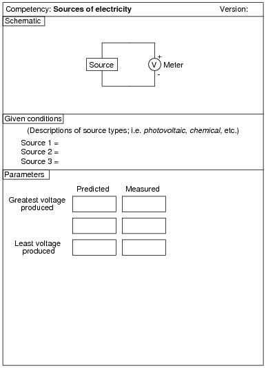
In this performance assessment, different electricity sources are suggested by way of conversion phenomena. In other words, the instructor will list such things as photovoltaic and piezoelectric, and students will have to choose the correct components to demonstrate conversion of energy into electrical form. Then, students will demonstrate each conversion for the instructor, ranking them in order of the voltage magnitude generated by each demonstration.
The purpose of this exercise is not only for students to obtain a practical understanding of electricity sources, but also to understand the relative magnitudes of each one. It is important for students to know, for instance, that thermoelectricity is a rather weak effect compared to piezoelectricity. This will help them understand the relative sensitivity of sensors and other electrical devices in the future.
Possible sources to list for student demonstration are:
- �
- Photovoltaic
- �
- Piezoelectric
- �
- Electromagnetic
- �
- Chemical
- �
- Thermoelectric
Of course, your selection of sources for student demonstration depends on the parts and equipment available to them.
Question 13:
|
|
Notes:
Use a variable-voltage, regulated power supply to supply any amount of DC voltage below 30 volts. Specify a standard resistor value, somewhere between 1 kW and 100 kW (1k5, 2k2, 2k7, 3k3, 4k7, 5k1, 6k8, 10k, 22k, 33k, 39k 47k, 68k, etc.).
Question 14:
|
|
Notes:
Use a variable-voltage, regulated power supply to supply any amount of DC voltage below 30 volts. Specify a standard resistor value, somewhere between 1 kW and 100 kW (1k5, 2k2, 2k7, 3k3, 4k7, 5k1, 6k8, 10k, 22k, 33k, 39k 47k, 68k, etc.).
Question 15:
|
|
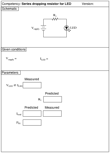
Notes:
Use a variable-voltage, regulated power supply to supply any amount of DC voltage below 30 volts. If using this question as a lab exercise rather than an assessment, I recommend specifying a voltage that is standard for batteries, so students don't necessarily have to have an adjustable power supply available to do this lab.
In this exercise, the student must both quantitatively and qualitatively analyze the circuit, because the ideal resistor value probably does not exist. As the instructor, it is you task to choose voltage and current specifications that preclude exact solutions with common resistor values.
Question 16:
|
|
Notes:
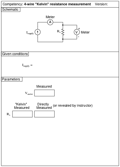
You will need to provide some low-resistance specimens for your students to measure using this technique. Motor armature coils work well for this purpose, as do large power resistors with the labels scratched off.
Question 17:
|
|
Notes:
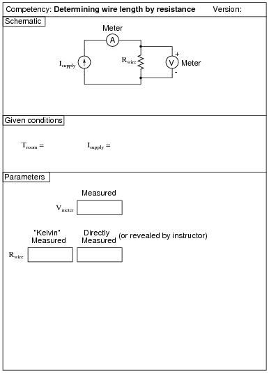
You will need to provide some spools of wire for your students to measure using this technique. Your students will need to find wire tables correlating length with resistance (at different temperatures, if the room temperature is significantly different from the standard temperature given in the table).
Question 18:
|
|
Notes:
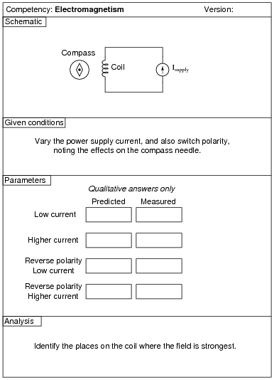
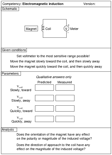
Old solenoid valve coils work very well for this exercise, as do spools of wire with large steel bolts passed through the center. Students may also wind their own coils using small-gauge magnet wire and a steel bolt. If the coils are hollow, you may experiment with and without ferrous cores, to demonstrate the effects of a ferromagnetic flux path on the field strength produced.
Question 19:
|
|
Notes:
Old solenoid valve coils work very well for this exercise, as do spools of wire with large steel bolts passed through the center. Students may also wind their own coils using small-gauge magnet wire and a steel bolt.
Please note that students will not be able to predict the polarity of the induced voltage unless they know the rotation of the coil windings and the polarity of their magnet. This will only be possible if the windings are exposed to view or if the students wind their own coils, and if the magnet has its poles labeled "North" and "South" (or if this is determined experimentally by using the magnet as a compass).
Use magnets that are as strong as possible, and that have their poles on the physical ends. This may seem like a strange request, but I've seen students bring some unusual magnets to class for this experiment, whose poles are not located on the ends. One type of magnet that works well is the so-called "cow magnet," used by cattle ranchers to protect cows' multiple stomachs from injury from ingestion of fence staples and other ferromagnetic objects. These are a few inches long, cylindrical in shape (so the cow can swallow it like a big pill), and quite strong.
If students are using analog multimeters to measure the coil's induced voltage, be sure to keep the multimeter far away from the magnet. Analog meter movements are generally quite sensitive to external magnetic fields and may register falsely if positioned too close to a strong magnet.
Question 20:
|
|
Notes:
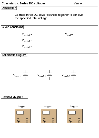
Use variable-voltage, regulated power supplies to supply any amount of DC voltage below 30 volts.
Question 21:
|
|
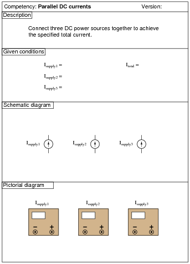
Caution! Consult your instructor to see how to set up each power supply to be a safe current source before attempting to connect them together!
Notes:
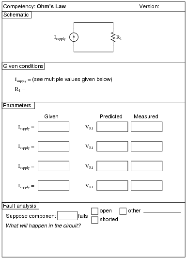
Use regulated power supplies with adjustable current limits to act as current sources (voltage adjustments set to "full" while current adjustments set the desired output current for each). Keep the currents less than one amp for each supply.
Question 22:
|
|
Notes:
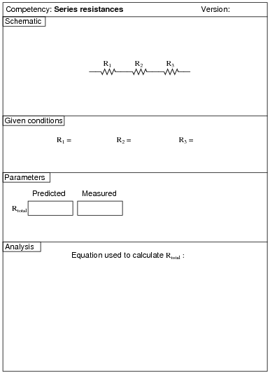
Specify standard resistor values, all between 1 kW and 100 kW (1k5, 2k2, 2k7, 3k3, 4k7, 5k1, 6k8, 10k, 22k, 33k, 39k 47k, 68k, etc.).
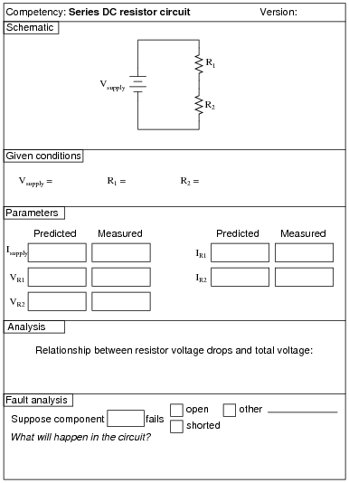
Question 23:
|
|
Notes:
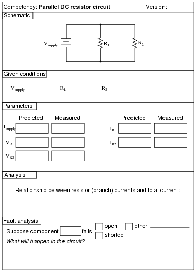
Use a variable-voltage, regulated power supply to supply any amount of DC voltage below 30 volts. Specify standard resistor values, all between 1 kW and 100 kW (1k5, 2k2, 2k7, 3k3, 4k7, 5k1, 6k8, 10k, 22k, 33k, 39k 47k, 68k, etc.).
An extension of this exercise is to incorporate troubleshooting questions. Whether using this exercise as a performance assessment or simply as a concept-building lab, you might want to follow up your students' results by asking them to predict the consequences of certain circuit faults.
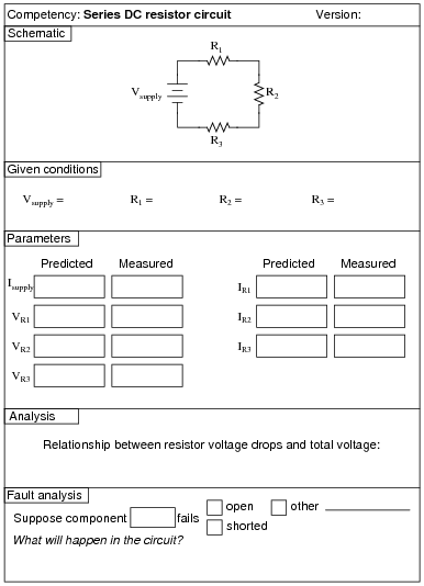
Question 24:
|
|
Notes:
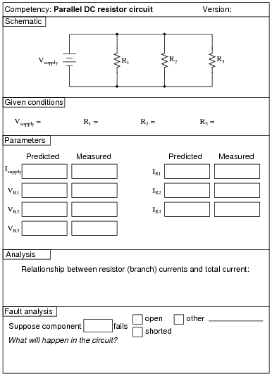
Use a variable-voltage, regulated power supply to supply any amount of DC voltage below 30 volts. Specify standard resistor values, all between 1 kW and 100 kW (1k5, 2k2, 2k7, 3k3, 4k7, 5k1, 6k8, 8k2, 10k, 22k, 33k, 39k 47k, 68k, 82k, etc.).
An extension of this exercise is to incorporate troubleshooting questions. Whether using this exercise as a performance assessment or simply as a concept-building lab, you might want to follow up your students' results by asking them to predict the consequences of certain circuit faults.
Question 25:
|
|
Notes:
Use a variable-voltage, regulated power supply to supply any amount of DC voltage below 30 volts. For added challenge, set the power supply voltage high enough (at least 15 volts) that a 1/4 watt resistor will be inadequately rated for the power dissipation.
An extension of this exercise is to incorporate troubleshooting questions. Whether using this exercise as a performance assessment or simply as a concept-building lab, you might want to follow up your students' results by asking them to predict the consequences of certain circuit faults.
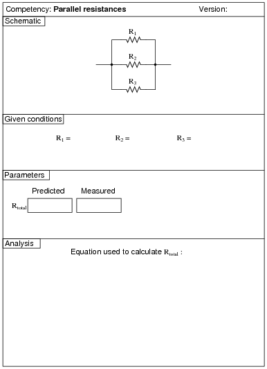
Question 26:
|
|
Notes:
Specify standard resistor values, all between 1 kW and 100 kW (1k5, 2k2, 2k7, 3k3, 4k7, 5k1, 6k8, 10k, 22k, 33k, 39k 47k, 68k, etc.).
Question 27:
|
|
Notes:
Use a variable-voltage, regulated power supply to supply any amount of DC voltage below 30 volts. Specify standard resistor values, all between 1 kW and 100 kW (1k5, 2k2, 2k7, 3k3, 4k7, 5k1, 6k8, 10k, 22k, 33k, 39k 47k, 68k, etc.).
An extension of this exercise is to incorporate troubleshooting questions. Whether using this exercise as a performance assessment or simply as a concept-building lab, you might want to follow up your students' results by asking them to predict the consequences of certain circuit faults.
Question 28:
|
|
Notes:
Use a variable-voltage, regulated power supply to supply any amount of DC voltage below 30 volts. Specify standard resistor values, all between 1 kW and 100 kW (1k5, 2k2, 2k7, 3k3, 4k7, 5k1, 6k8, 8k2, 10k, 22k, 33k, 39k 47k, 68k, 82k, etc.).
An extension of this exercise is to incorporate troubleshooting questions. Whether using this exercise as a performance assessment or simply as a concept-building lab, you might want to follow up your students' results by asking them to predict the consequences of certain circuit faults.
Question 29:
|
|
Notes:
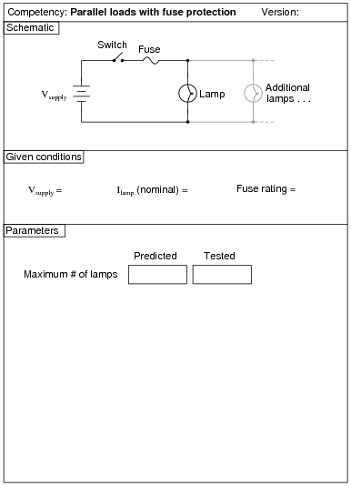
Use a variable-voltage, regulated power supply to supply a suitable DC voltage for the incandescent lamp. Set the power supply current limit such that it outputs enough to blow the fuse, but not enough to damage anything else. The fuse needs to be rated for a current value practical for a reasonable number of parallel-connected lamps.