Performance-based assessments for analog integrated circuit competencies
Question 1:
|
|
Notes:
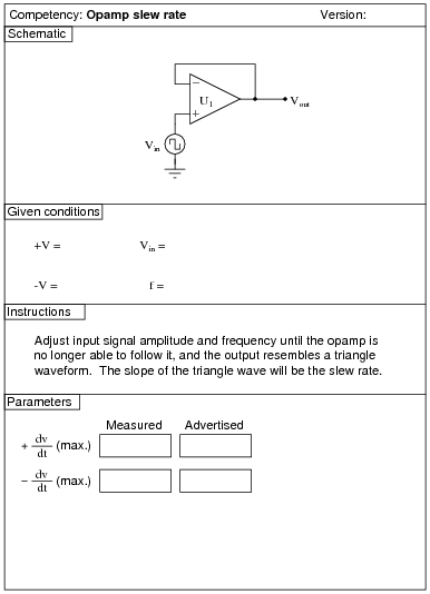
Use a dual-voltage, regulated power supply to supply power to the opamp. I recommend using a ßlow" op-amp to make the slewing more easily noticeable. If a student chooses a relatively fast-slew op-amp such as the TL082, their signal frequency may have to go up into the megahertz range before the slewing becomes evident. At these speeds, parasitic inductance and capacitance in their breadboards and test leads will cause bad "ringing" and other artifacts muddling the interpretation of the circuit's performance.
I have had good success using the following values:
- �
- +V = +12 volts
- �
- -V = -12 volts
- �
- Vin = 4 V peak-to-peak, at 300 kHz
- �
- U1 = one-half of LM1458 dual operational amplifier
An extension of this exercise is to incorporate troubleshooting questions. Whether using this exercise as a performance assessment or simply as a concept-building lab, you might want to follow up your students' results by asking them to predict the consequences of certain circuit faults.
Question 2:
|
|
Notes:
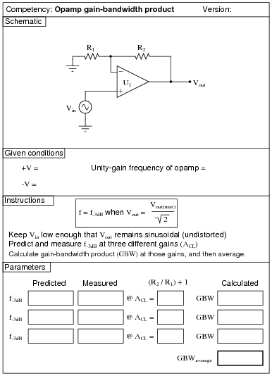
The purpose of this exercise is to empirically determine the gain-bandwidth product (GBW) of a closed-loop opamp amplifier circuit by setting it up for three different closed-loop gains (ACL), measuring the cutoff frequency (f-3dB) at those gains, and calculating the product of the two (ACL f-3dB) at each gain. Since this amplifier is DC-coupled, there is no need to measure a lower cutoff frequency in order to calculate bandwidth, just the high cutoff frequency.
What GBW tells us is that any opamp has the tendency to act as a low-pass filter, its cutoff frequency being dependent on how much gain we are trying to get out of the opamp. We can have large gain at modest frequencies, or a high bandwidth at modest gain, but not both! This lab exercise is designed to let students see this limitation. As they set up their opamp circuits with greater and greater gains ([(R2)/(R1)] + 1), they will notice the opamp "cut off" like a low-pass filter at lower and lower frequencies.
For the "given" value of unity-gain frequency, you must consult the datasheet for the opamp you choose. I like to use the popular TL082 BiFET opamp for a lot of AC circuits, because it delivers good performance at a modest price and excellent availability. However, the GBW for the TL082 is so high (3 MHz typical) that breadboard and wiring layout become issues when testing at low gains, due to the resulting high frequencies necessary to show cutoff. The venerable 741 is a better option because its gain-bandwidth product is significantly lower (1 to 1.5 MHz typical).
It is very important in this exercise to maintain an undistorted opamp output, even when the closed-loop gain is very high. Failure to do so will result in the f-3dB points being skewed by slew-rate limiting. What we're looking for here are the cutoff frequencies resulting from loss of small-signal open-loop gain (AOL) inside the opamp. To maintain small-signal status, we must ensure the signal is not being distorted!
Some typical values I was able to calculate for GBW product are 3.8 ×10⁶ for the BiFET TL082, 1.5 ×10⁶ for the LM1458, and around 800 ×103 for the LM741C.
An extension of this exercise is to incorporate troubleshooting questions. Whether using this exercise as a performance assessment or simply as a concept-building lab, you might want to follow up your students' results by asking them to predict the consequences of certain circuit faults.
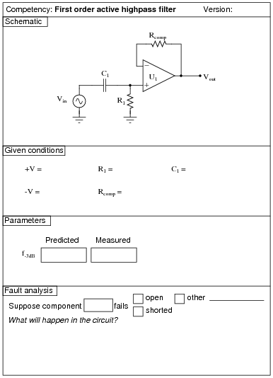
Question 3:

|
|
Notes:
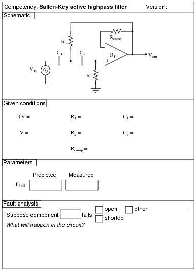
I recommend setting the function generator output for 1 volt, to make it easier for students to measure the point of "cutoff". You may set it at some other value, though, if you so choose (or let students set the value themselves when they test the circuit!).
For capacitors, I recommend students choose three (3) capacitors of equal value if they wish to build the Sallen-Key circuit with a Butterworth response (where C2 = 2 C1). Capacitor C1 will be a single capacitor, while capacitor C2 will be two capacitors connected in parallel. This generally ensures a more precise 1:2 ratio than choosing individual components.
I also recommend having students use an oscilloscope to measure AC voltage in a circuit such as this, because some digital multimeters have difficulty accurately measuring AC voltage much beyond line frequency range. I find it particularly helpful to set the oscilloscope to the "X-Y" mode so that it draws a thin line on the screen rather than sweeps across the screen to show an actual waveform. This makes it easier to measure peak-to-peak voltage.
Values that have proven to work well for this exercise are given here, although of course many other values are possible:
- �
- +V = +12 volts
- �
- -V = -12 volts
- �
- R1 = 10 kW
- �
- R2 = 10 kW
- �
- Rcomp = 20 kW (actually, two 10 kW resistors in series)
- �
- C1 = 0.001 mF
- �
- C2 = 0.002 mF (actually, two 0.001 mF capacitors in parallel)
- �
- U1 = one-half of LM1458 dual operational amplifier
This combination of components gave a predicted cutoff frequency of 11.25 kHz, with an actual cutoff frequency (not factoring in component tolerances) of 11.36 kHz.
Question 4:
|
|
Notes:
I recommend setting the function generator output for 1 volt, to make it easier for students to measure the point of "cutoff". You may set it at some other value, though, if you so choose (or let students set the value themselves when they test the circuit!).
For resistors, I recommend students choose three (3) resistors of equal value if they wish to build the Sallen-Key circuit with a Butterworth response (where R2 = 1/2 R1). Resistor R1 will be a single resistor, while resistor R2 will be two resistors connected in parallel. This generally ensures a more precise 1:2 ratio than choosing individual components.
I also recommend having students use an oscilloscope to measure AC voltage in a circuit such as this, because some digital multimeters have difficulty accurately measuring AC voltage much beyond line frequency range. I find it particularly helpful to set the oscilloscope to the "X-Y" mode so that it draws a thin line on the screen rather than sweeps across the screen to show an actual waveform. This makes it easier to measure peak-to-peak voltage.
Values that have proven to work well for this exercise are given here, although of course many other values are possible:
- �
- +V = +12 volts
- �
- -V = -12 volts
- �
- R1 = 10 kW
- �
- R2 = 5 kW (actually, two 10 kW resistors in parallel)
- �
- Rcomp = 10 kW
- �
- C1 = 0.002 mF (actually, two 0.001 mF capacitors in parallel)
- �
- C2 = 0.002 mF (actually, two 0.001 mF capacitors in parallel)
- �
- U1 = one-half of LM1458 dual operational amplifier
This combination of components gave a predicted cutoff frequency of 11.25 kHz, with an actual cutoff frequency (not factoring in component tolerances) of 11.11 kHz.
Question 5:
|
|
Notes:
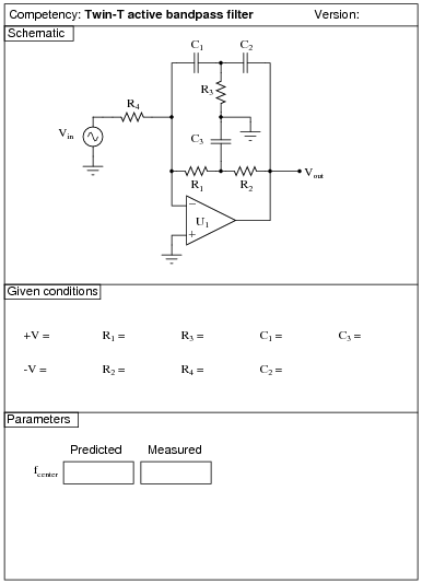
I also recommend having students use an oscilloscope to measure AC voltage in a circuit such as this, because some digital multimeters have difficulty accurately measuring AC voltage much beyond line frequency range. I find it particularly helpful to set the oscilloscope to the "X-Y" mode so that it draws a thin line on the screen rather than sweeps across the screen to show an actual waveform. This makes it easier to measure peak-to-peak voltage.
Values that have proven to work well for this exercise are given here, although of course many other values are possible:
- �
- +V = +12 volts
- �
- -V = -12 volts
- �
- R1 = 10 kW
- �
- R2 = 10 kW
- �
- R3 = 5 kW (actually, two 10 kW resistors in parallel)
- �
- R4 = 100 kW
- �
- C1 = 0.001 mF
- �
- C2 = 0.001 mF
- �
- C3 = 0.002 mF (actually, two 0.001 mF capacitors in parallel)
- �
- U1 = one-half of LM1458 dual operational amplifier
This combination of components gave a predicted center frequency of 15.92 kHz, with an actual cutoff frequency (not factoring in component tolerances) of 15.63 kHz.
Question 6:
|
|
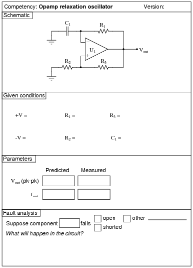
Notes:
Use a dual-voltage, regulated power supply to supply power to the opamp. Specify standard resistor values, all between 1 kW and 100 kW (1k5, 2k2, 2k7, 3k3, 4k7, 5k1, 6k8, 10k, 22k, 33k, 39k 47k, 68k, etc.).
I have had good success using the following values:
- �
- +V = +12 volts
- �
- -V = -12 volts
- �
- R1 = 10 kW
- �
- R2 = 10 kW
- �
- R3 = 10 kW
- �
- C1 = 0.1 mF
- �
- U1 = one-half of LM1458 dual operational amplifier
An extension of this exercise is to incorporate troubleshooting questions. Whether using this exercise as a performance assessment or simply as a concept-building lab, you might want to follow up your students' results by asking them to predict the consequences of certain circuit faults.
Question 7:
|
|
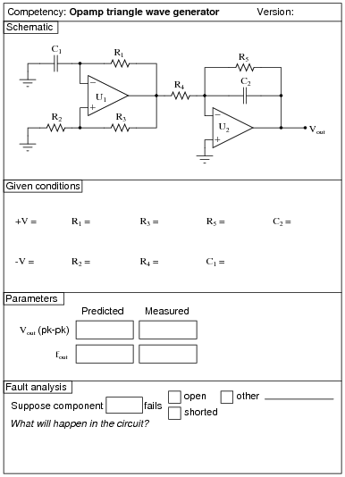
Notes:
Use a dual-voltage, regulated power supply to supply power to the opamp. Specify standard resistor values, all between 1 kW and 100 kW (1k5, 2k2, 2k7, 3k3, 4k7, 5k1, 6k8, 10k, 22k, 33k, 39k 47k, 68k, etc.).
I have had good success using the following values:
- �
- +V = +12 volts
- �
- -V = -12 volts
- �
- R1 = 10 kW
- �
- R2 = 10 kW
- �
- R3 = 10 kW
- �
- R4 = 10 kW
- �
- R5 = 100 kW
- �
- C1 = 0.1 mF
- �
- C2 = 0.47 mF
- �
- U1 = one-half of LM1458 dual operational amplifier
- �
- U2 = other half of LM1458 dual operational amplifier
It is a good idea to choose capacitor C2 as a larger value than capacitor C1, so that the second opamp does not saturate.
An extension of this exercise is to incorporate troubleshooting questions. Whether using this exercise as a performance assessment or simply as a concept-building lab, you might want to follow up your students' results by asking them to predict the consequences of certain circuit faults.
Question 8:
|
|
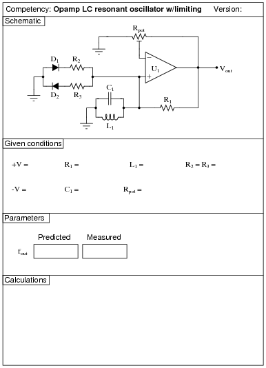
Notes:
Use a dual-voltage, regulated power supply to supply power to the opamp. Specify standard resistor values, all between 1 kW and 100 kW (1k5, 2k2, 2k7, 3k3, 4k7, 5k1, 6k8, 10k, 22k, 33k, 39k 47k, 68k, etc.).
I have had good success using the following values:
- �
- +V = +12 volts
- �
- -V = -12 volts
- �
- R1 = 10 kW
- �
- R2 = R3 = 1 kW
- �
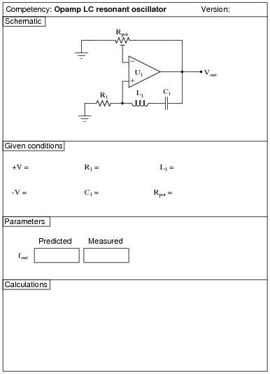
- Rpot = 10 kW multi-turn
- �
- C1 = 0.001 mF or 0.47 mF
- �
- L1 = 100 mH
- �
- D1 = D2 = 1N4148
- �
- U1 = one-half of LM1458 dual operational amplifier
With the presence of the amplitude-limiting diodes D1 and D2, the potentiometer adjustment is not nearly as sensitive as without. Try removing both diodes to see what happens when there is no amplitude limiting at all! Students will have to finely adjust the multi-turn potentiometer to achieve a good sine wave (meeting the Barkhausen criterion). With the diodes in place, however, you may adjust the potentiometer for a loop gain just above unity with the only consequence being slight distortion of the waveform rather than severe distortion.
An extension of this exercise is to incorporate troubleshooting questions. Whether using this exercise as a performance assessment or simply as a concept-building lab, you might want to follow up your students' results by asking them to predict the consequences of certain circuit faults.
Question 9:
|
|
Notes:
An extension of this exercise is to incorporate troubleshooting questions. Whether using this exercise as a performance assessment or simply as a concept-building lab, you might want to follow up your students' results by asking them to predict the consequences of certain circuit faults.
Question 10:
|
|
Notes:
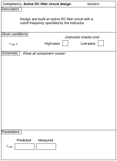
Use a sine-wave function generator for the AC voltage source. Specify a cutoff frequency within the audio range.
I recommend setting the function generator output for 1 volt, to make it easier for students to measure the point of "cutoff". You may set it at some other value, though, if you so choose (or let students set the value themselves when they test the circuit!).
I also recommend having students use an oscilloscope to measure AC voltage in a circuit such as this, because some digital multimeters have difficulty accurately measuring AC voltage much beyond line frequency range. I find it particularly helpful to set the oscilloscope to the "X-Y" mode so that it draws a thin line on the screen rather than sweeps across the screen to show an actual waveform. This makes it easier to measure peak-to-peak voltage.
Question 11:
|
|
Notes:
An extension of this exercise is to incorporate troubleshooting questions. Whether using this exercise as a performance assessment or simply as a concept-building lab, you might want to follow up your students' results by asking them to predict the consequences of certain circuit faults.
Question 12:
|
|
Notes:
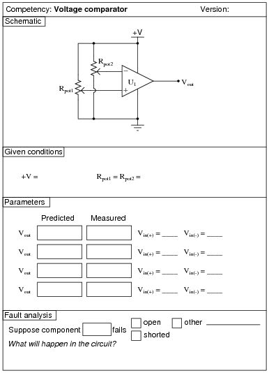
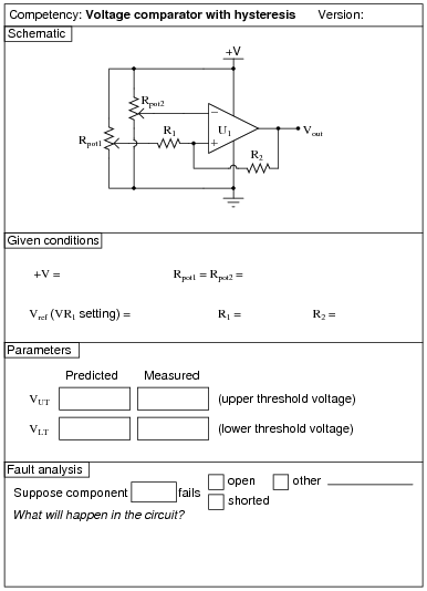
You may wish to use either an operational amplifier or a true comparator for this exercise. Whether or not the specific device has rail-to-rail output swing capability is your choice as well.
An extension of this exercise is to incorporate troubleshooting questions. Whether using this exercise as a performance assessment or simply as a concept-building lab, you might want to follow up your students' results by asking them to predict the consequences of certain circuit faults.
Question 13:
|
|
Notes:
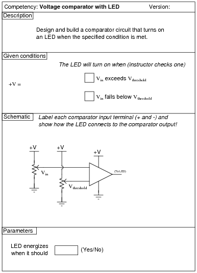
Students are free to connect the LED to the comparator in any way they choose (current-sourcing or current-sinking).
An extension of this exercise is to incorporate troubleshooting questions. Whether using this exercise as a performance assessment or simply as a concept-building lab, you might want to follow up your students' results by asking them to predict the consequences of certain circuit faults.
Question 14:
|
|
Notes:
You may wish to use either an operational amplifier or a true comparator for this exercise. Whether or not the specific device has rail-to-rail output swing capability is your choice as well.
An extension of this exercise is to incorporate troubleshooting questions. Whether using this exercise as a performance assessment or simply as a concept-building lab, you might want to follow up your students' results by asking them to predict the consequences of certain circuit faults.
Question 15:
|
|
Notes:
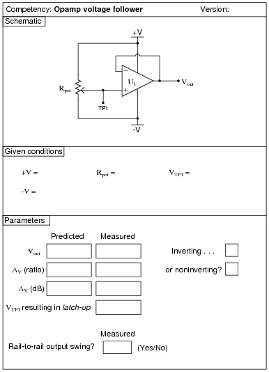
Use a dual-voltage, regulated power supply to supply power to the opamp.
I have had good success using the following values:
- �
- +V = +12 volts
- �
- -V = -12 volts
- �
- VTP1 = Any voltage well between +V and -V
- �
- Rpot = 10 kW linear potentiometer
- �
- U1 = TL081 BiFET operational amplifier (or one-half of a TL082)
In order to demonstrate latch-up, you must have an op-amp capable of latching up. Thus, you should avoid op-amps such as the LM741 and LM1458. I recommend using an op-amp such as the TL082 for this exercise because it not only latches up, but also does not swing its output voltage rail-to-rail. Students need to see both these common limitations when they first learn how to use op-amps.
In case your students ask, test point TP1 is for measuring the output of the potentiometer rather than as a place to inject external signals into. All you need to connect to TP1 is a voltmeter!
An extension of this exercise is to incorporate troubleshooting questions. Whether using this exercise as a performance assessment or simply as a concept-building lab, you might want to follow up your students' results by asking them to predict the consequences of certain circuit faults.
Question 16:
|
|
Notes:
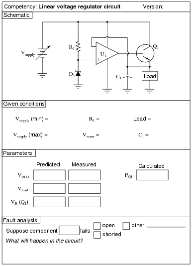
Use a power transistor for this circuit, as general-purpose signal transistors may not have sufficient power dissipation ratings to survive the loading students may put them through! I recommend a small DC motor as a load. An electric motor offers an easy way to increase electrical loading by placing a mechanical load on the shaft. By doing this, students can see for themselves how well the circuit maintains load voltage (resisting voltage ßag" under increasing load current).
I have found that this circuit is excellent for getting students to understand how negative feedback really works. Here, the opamp adjusts the power transistor's base voltage to whatever it needs to be in order to maintain the load voltage at the same level as the reference set by the zener diode. Any sort of loss incurred by the transistor (most notably VBE) is automatically compensated for by the opamp.
An extension of this exercise is to incorporate troubleshooting questions. Whether using this exercise as a performance assessment or simply as a concept-building lab, you might want to follow up your students' results by asking them to predict the consequences of certain circuit faults.
Question 17:
|
|
Notes:
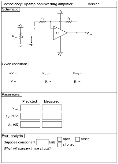
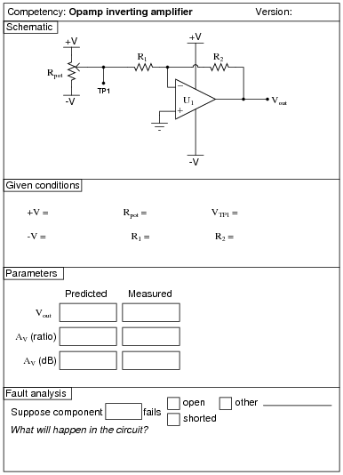
Use a dual-voltage, regulated power supply to supply power to the opamp. Specify standard resistor values, all between 1 kW and 100 kW (1k5, 2k2, 2k7, 3k3, 4k7, 5k1, 6k8, 10k, 22k, 33k, 39k 47k, 68k, etc.).
I have had good success using the following values:
- �
- +V = +12 volts
- �
- -V = -12 volts
- �
- VTP1 = Any voltage well between +V and -V not resulting in output saturation
- �
- R1 = 10 kW
- �
- R2 = 27 kW
- �
- Rpot = 10 kW linear potentiometer
- �
- U1 = TL081 BiFET operational amplifier (or one-half of a TL082)
An extension of this exercise is to incorporate troubleshooting questions. Whether using this exercise as a performance assessment or simply as a concept-building lab, you might want to follow up your students' results by asking them to predict the consequences of certain circuit faults.
Question 18:
|
|
Notes:
Use a dual-voltage, regulated power supply to supply power to the opamp. Specify standard resistor values, all between 1 kW and 100 kW (1k5, 2k2, 2k7, 3k3, 4k7, 5k1, 6k8, 10k, 22k, 33k, 39k 47k, 68k, etc.).
I have had good success using the following values:
- �
- +V = +12 volts
- �
- -V = -12 volts
- �
- VTP1 = Any voltage well between +V and -V not resulting in output saturation
- �
- R1 = 10 kW
- �
- R2 = 27 kW
- �
- Rpot = 10 kW linear potentiometer
- �
- U1 = TL081 BiFET operational amplifier (or one-half of a TL082)
An extension of this exercise is to incorporate troubleshooting questions. Whether using this exercise as a performance assessment or simply as a concept-building lab, you might want to follow up your students' results by asking them to predict the consequences of certain circuit faults.
Question 19:
|
|
Notes:
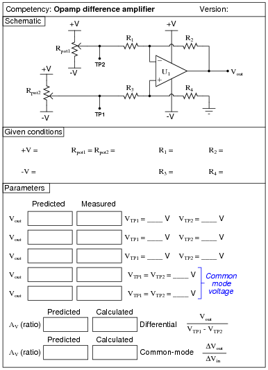
Use a dual-voltage, regulated power supply to supply power to the opamp. Specify all four resistors as equal value, between 1 kW and 100 kW (1k5, 2k2, 2k7, 3k3, 4k7, 5k1, 6k8, 10k, 22k, 33k, 39k 47k, 68k, etc.). This will ensure a differential voltage gain of unity. If you want to have a different voltage gain, then by all means specify these resistor values however you see fit!
Differential gain is calculated by averaging the quotients of each measured Vout value with its respective Vin(+) - Vin(-) differential input voltage. Common-mode gain is calculated by dividing the difference in output voltages (DVout) by the difference in common-mode input voltages (DVin).
An extension of this exercise is to incorporate troubleshooting questions. Whether using this exercise as a performance assessment or simply as a concept-building lab, you might want to follow up your students' results by asking them to predict the consequences of certain circuit faults.
Question 20:
|
|
Notes:
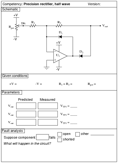
Choose both positive input voltage values and negative input voltage values, so that students may predict and measure the output of this circuit under both types of conditions. The choice of diodes is not critical, as any rectifier diodes will work. The two resistor values should be equal, and at least as high as the potentiometer value. I recommend a 10 kW potentiometer and 15 kW resistors.
A good follow-up question to ask is what would be required to change the polarity of this half-wave precision rectifier circuit.
An extension of this exercise is to incorporate troubleshooting questions. Whether using this exercise as a performance assessment or simply as a concept-building lab, you might want to follow up your students' results by asking them to predict the consequences of certain circuit faults.
Question 21:
|
|
Notes:
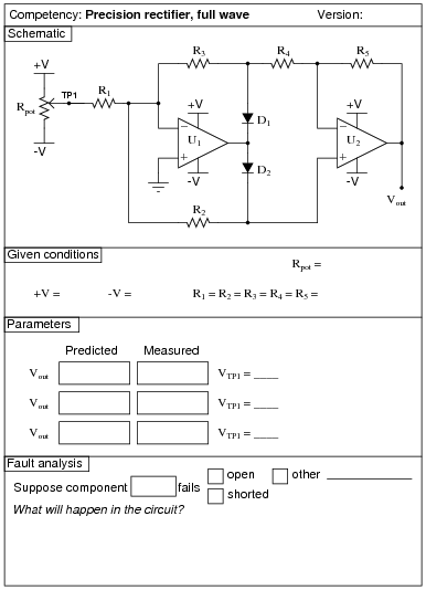
Choose both positive input voltage values and negative input voltage values, so that students may predict and measure the output of this circuit under both types of conditions. The choice of diodes is not critical, as any rectifier diodes will work. All resistor values need to be equal, and at least as high as the potentiometer value. I recommend a 10 kW potentiometer and 15 kW resistors.
A good follow-up question to ask is what would be required to change the polarity of this full-wave precision rectifier circuit.
An extension of this exercise is to incorporate troubleshooting questions. Whether using this exercise as a performance assessment or simply as a concept-building lab, you might want to follow up your students' results by asking them to predict the consequences of certain circuit faults.
Question 22:
|
|
Notes:
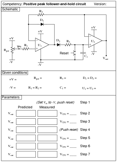
Choose values for Vin that show the circuit's ability to "hold" the last highest (most positive) input voltage.
I have found these values to work well:
- �
- +V = +12 volts
- �
- -V = -12 volts
- �
- R1 = R2 = 10 kW
- �
- R3 = 10 kW
- �
- Rpot = 10 kW
- �
- C1 = 1 mF (non-electrolytic, low leakage polyester or ceramic)
- �
- D1 = D2 = 1N4148 switching diode
- �
- U1 = U2 = TL082 dual BiFET opamp
The TL082 opamp works well in this circuit for three reasons: first, it is a dual opamp, providing both necessary opamps in a single 8-pin package. Second, its JFET input stage provides the low input bias currents necessary to avoid draining the capacitor too rapidly. Third, it is free from latch-up, which makes it possible to reset the capacitor voltage to the full (negative) rail voltage and still have a valid output.
An extension of this exercise is to incorporate troubleshooting questions. Whether using this exercise as a performance assessment or simply as a concept-building lab, you might want to follow up your students' results by asking them to predict the consequences of certain circuit faults.
Question 23:
|
|
Notes:
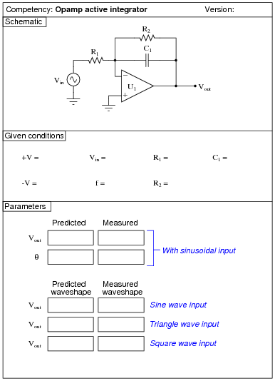
Use a dual-voltage, regulated power supply to supply power to the opamp. Specify standard resistor values, all between 1 kW and 100 kW (1k5, 2k2, 2k7, 3k3, 4k7, 5k1, 6k8, 10k, 22k, 33k, 39k 47k, 68k, etc.).
I have had good success using the following values:
- �
- +V = +12 volts
- �
- -V = -12 volts
- �
- Vin = 1 V peak-to-peak, at 10 kHz
- �
- R1 = 10 kW
- �
- R2 = 100 kW
- �
- C1 = 0.001 mF
- �
- U1 = one-half of LM1458 dual operational amplifier
A good follow-up activity for this circuit is to change the input frequency, and predict/measure the phase shift (Q) between input and output for sinusoidal waveforms. The results may be surprising, especially if you are accustomed to the behavior of a passive integrator circuit.
An extension of this exercise is to incorporate troubleshooting questions. Whether using this exercise as a performance assessment or simply as a concept-building lab, you might want to follow up your students' results by asking them to predict the consequences of certain circuit faults.
Question 24:
|
|
Notes:
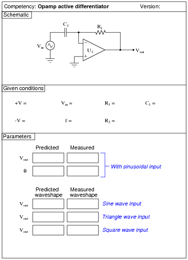
Use a dual-voltage, regulated power supply to supply power to the opamp. Specify standard resistor values, all between 1 kW and 100 kW (1k5, 2k2, 2k7, 3k3, 4k7, 5k1, 6k8, 10k, 22k, 33k, 39k 47k, 68k, etc.).
I have had good success using the following values:
- �
- +V = +12 volts
- �
- -V = -12 volts
- �
- Vin = 1 V peak-to-peak, at 1 kHz
- �
- R1 = 1 kW
- �
- C1 = 0.1 mF
- �
- U1 = one-half of LM1458 dual operational amplifier
A good follow-up activity for this circuit is to change the input frequency, and predict/measure the phase shift (Q) between input and output for sinusoidal waveforms. The results may be surprising, especially if you are accustomed to the behavior of a passive differentiator circuit.
Students may become dismayed if they see a "noisy" output waveform, especially if they have just completed the active integrator circuit exercise. Explain to them that noise on the output of a differentiator circuit is quite normal due to the proper function of a differentiator: to provide voltage amplification proportional to the frequency of the signal. This means that even a little high-frequency noise on the input will show up on the output in magnified form. Remind them that this is what differentiators are supposed to do, and it is not some idiosyncrasy of the circuit.
Active differentiator circuits are great for displaying distortions in the input waveform. While pure sine waves in should produce pure sine waves out, and pure triangle waves in should produce pure square waves out, deviations from these "pure" waveform types will produce output waveforms that obviously deviate from their ideal forms. Usually, a "distorted" output does not indicate a fault in the circuit, but rather a subtle distortion in the input signal that would otherwise go unseen due to its miniscule magnitude.
An extension of this exercise is to incorporate troubleshooting questions. Whether using this exercise as a performance assessment or simply as a concept-building lab, you might want to follow up your students' results by asking them to predict the consequences of certain circuit faults.
Question 25:
|
|
Notes:
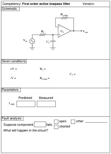
I recommend setting the function generator output for 1 volt, to make it easier for students to measure the point of "cutoff". You may set it at some other value, though, if you so choose (or let students set the value themselves when they test the circuit!).
I also recommend having students use an oscilloscope to measure AC voltage in a circuit such as this, because some digital multimeters have difficulty accurately measuring AC voltage much beyond line frequency range. I find it particularly helpful to set the oscilloscope to the "X-Y" mode so that it draws a thin line on the screen rather than sweeps across the screen to show an actual waveform. This makes it easier to measure peak-to-peak voltage.
Be sure to choose component values that will yield a frequency well within the range that the specified opamp can handle! It would be foolish, for example, to specify a cutoff frequency in the megahertz range if the particular opamp being used was an LM741.
Question 26:
|
|
Notes:
I recommend setting the function generator output for 1 volt, to make it easier for students to measure the point of "cutoff". You may set it at some other value, though, if you so choose (or let students set the value themselves when they test the circuit!).
I also recommend having students use an oscilloscope to measure AC voltage in a circuit such as this, because some digital multimeters have difficulty accurately measuring AC voltage much beyond line frequency range. I find it particularly helpful to set the oscilloscope to the "X-Y" mode so that it draws a thin line on the screen rather than sweeps across the screen to show an actual waveform. This makes it easier to measure peak-to-peak voltage.
Be sure to choose component values that will yield a frequency well within the range that the specified opamp can handle! It would be foolish, for example, to specify a cutoff frequency in the megahertz range if the particular opamp being used was an LM741.
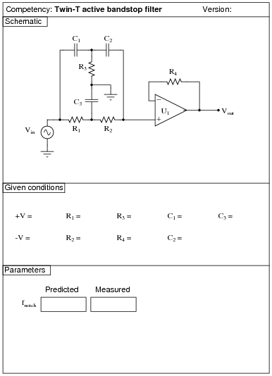
Question 27:
|
|
Notes:
I also recommend having students use an oscilloscope to measure AC voltage in a circuit such as this, because some digital multimeters have difficulty accurately measuring AC voltage much beyond line frequency range. I find it particularly helpful to set the oscilloscope to the "X-Y" mode so that it draws a thin line on the screen rather than sweeps across the screen to show an actual waveform. This makes it easier to measure peak-to-peak voltage.
Values that have proven to work well for this exercise are given here, although of course many other values are possible:
- �
- +V = +12 volts
- �
- -V = -12 volts
- �
- R1 = 10 kW
- �
- R2 = 10 kW
- �
- R3 = 5 kW (actually, two 10 kW resistors in parallel)
- �
- R4 = 20 kW (actually, two 10 kW resistors in series)
- �
- C1 = 0.001 mF
- �
- C2 = 0.001 mF
- �
- C3 = 0.002 mF (actually, two 0.001 mF capacitors in parallel)
- �
- U1 = one-half of LM1458 dual operational amplifier
This combination of components gave a predicted notch frequency of 15.92 kHz, with an actual cutoff frequency (not factoring in component tolerances) of 15.87 kHz.
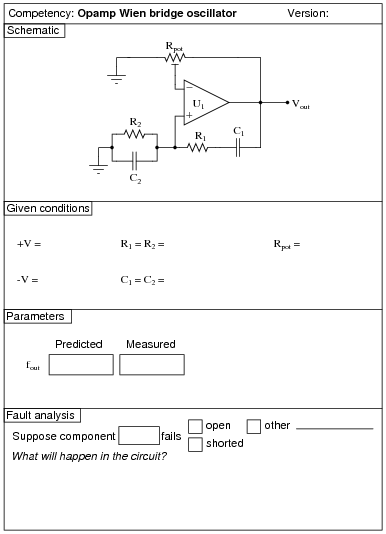
Question 28:
|
|
Notes:
Use a dual-voltage, regulated power supply to supply power to the opamp. Specify standard resistor values, all between 1 kW and 100 kW (1k5, 2k2, 2k7, 3k3, 4k7, 5k1, 6k8, 10k, 22k, 33k, 39k 47k, 68k, etc.).
I have had good success using the following values:
- �
- +V = +12 volts
- �
- -V = -12 volts
- �
- R1 = R2 = 10 kW
- �
- Rpot = 10 kW multi-turn
- �
- C1 = C2 = 0.001 mF
- �
- U1 = one-half of LM1458 dual operational amplifier
Note that due to the lack of automatic gain control in this circuit, the potentiometer adjustment is very sensitive! Students will have to finely adjust the multi-turn potentiometer to achieve a good sine wave (meeting the Barkhausen criterion).
An extension of this exercise is to incorporate troubleshooting questions. Whether using this exercise as a performance assessment or simply as a concept-building lab, you might want to follow up your students' results by asking them to predict the consequences of certain circuit faults.
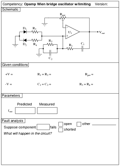
Question 29:
|
|
Notes:
Use a dual-voltage, regulated power supply to supply power to the opamp. Specify standard resistor values, all between 1 kW and 100 kW (1k5, 2k2, 2k7, 3k3, 4k7, 5k1, 6k8, 10k, 22k, 33k, 39k 47k, 68k, etc.).
I have had good success using the following values:
- �
- +V = +12 volts
- �
- -V = -12 volts
- �
- R1 = R2 = 10 kW
- �
- R3 = R4 = 10 kW
- �
- Rpot = 10 kW multi-turn
- �
- C1 = C2 = 0.001 mF
- �
- D1 = 1N4148
- �
- D2 = 1N4148
- �
- U1 = one-half of LM1458 dual operational amplifier
With the presence of the amplitude-limiting diodes D1 and D2, the potentiometer adjustment is not nearly as sensitive as without. Try removing both diodes to see what happens when there is no amplitude limiting at all! Students will have to finely adjust the multi-turn potentiometer to achieve a good sine wave (meeting the Barkhausen criterion). With the diodes in place, however, you may adjust the potentiometer for a loop gain just above unity with the only consequence being slight distortion of the waveform rather than severe distortion.
An extension of this exercise is to incorporate troubleshooting questions. Whether using this exercise as a performance assessment or simply as a concept-building lab, you might want to follow up your students' results by asking them to predict the consequences of certain circuit faults.
Question 30:
|
|
Notes:
Use a dual-voltage, regulated power supply to supply power to the opamp. Specify standard resistor values, all between 1 kW and 100 kW (1k5, 2k2, 2k7, 3k3, 4k7, 5k1, 6k8, 10k, 22k, 33k, 39k 47k, 68k, etc.).
I have had good success using the following values:
- �
- +V = +12 volts
- �
- -V = -12 volts
- �
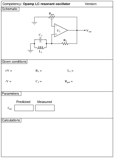
- R1 = 10 kW
- �
- Rpot = 10 kW multi-turn
- �
- C1 = 0.001 mF or 0.47 mF
- �
- L1 = 100 mH
- �
- U1 = one-half of LM1458 dual operational amplifier
Note that due to the lack of automatic gain control in this circuit, the potentiometer adjustment is very sensitive! Students will have to finely adjust the multi-turn potentiometer to achieve a good sine wave (meeting the Barkhausen criterion).
An extension of this exercise is to incorporate troubleshooting questions. Whether using this exercise as a performance assessment or simply as a concept-building lab, you might want to follow up your students' results by asking them to predict the consequences of certain circuit faults.
Question 31:
|
|
Notes:
Use a dual-voltage, regulated power supply to supply power to the opamp. Specify standard resistor values, all between 1 kW and 100 kW (1k5, 2k2, 2k7, 3k3, 4k7, 5k1, 6k8, 10k, 22k, 33k, 39k 47k, 68k, etc.).
I have had good success using the following values:
- �
- +V = +12 volts
- �
- -V = -12 volts
- �
- R1 = 10 kW
- �
- Rpot = 10 kW multi-turn
- �
- C1 = 0.001 mF or 0.47 mF
- �
- L1 = 100 mH
- �
- U1 = one-half of LM1458 dual operational amplifier
Note that due to the lack of automatic gain control in this circuit, the potentiometer adjustment is very sensitive! Students will have to finely adjust the multi-turn potentiometer to achieve a good sine wave (meeting the Barkhausen criterion).
An extension of this exercise is to incorporate troubleshooting questions. Whether using this exercise as a performance assessment or simply as a concept-building lab, you might want to follow up your students' results by asking them to predict the consequences of certain circuit faults.
Question 32:
|
|
Notes:
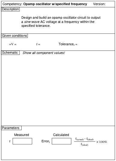
Students are free to choose any oscillator design that meets the criteria: sinusoidal output at a specified frequency.
An extension of this exercise is to incorporate troubleshooting questions. Whether using this exercise as a performance assessment or simply as a concept-building lab, you might want to follow up your students' results by asking them to predict the consequences of certain circuit faults.
Question 33:
|
|
Notes:
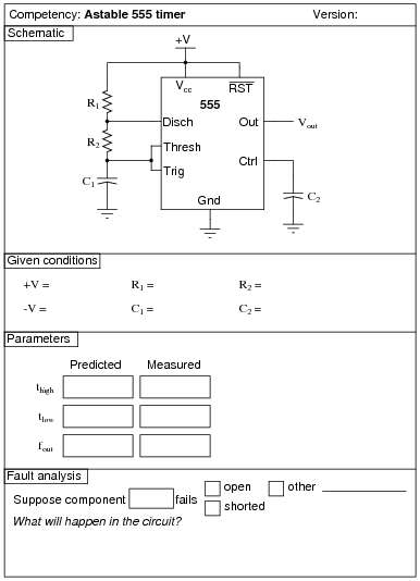
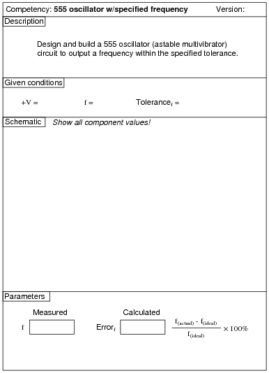
Students are free to choose any duty cycle they wish. The only performance criterion is output frequency.
An extension of this exercise is to incorporate troubleshooting questions. Whether using this exercise as a performance assessment or simply as a concept-building lab, you might want to follow up your students' results by asking them to predict the consequences of certain circuit faults.