Performance-based assessments for semiconductor circuit competencies
Question 1:
|
|
Notes:
Use a variable-voltage, regulated power supply to supply any amount of DC voltage below 30 volts. Specify standard resistor values, all between 1 kW and 100 kW (1k5, 2k2, 2k7, 3k3, 4k7, 5k1, 6k8, 10k, 22k, 33k, 39k 47k, 68k, etc.).
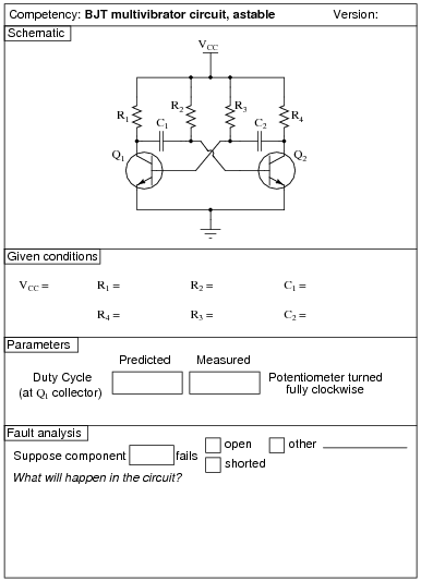
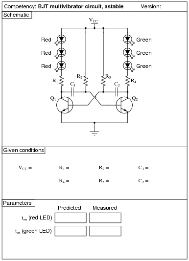
This circuit produces nice, sharp-edged square wave signals at the transistor collector terminals when resistors R1 and R4 are substantially smaller than resistors R2 and R3. This way, R2 and R3 dominate the capacitors' charging times, making calculation of duty cycle much more accurate. Component values I've used with success are 1 kW for R1 and R4, 100 kW for R2 and R3, and 0.1 mF for C1 and C2.
An extension of this exercise is to incorporate troubleshooting questions. Whether using this exercise as a performance assessment or simply as a concept-building lab, you might want to follow up your students' results by asking them to predict the consequences of certain circuit faults.
Question 2:
|
|
Notes:
Use a variable-voltage, regulated power supply to supply any amount of DC voltage below 30 volts. Specify standard resistor values, all between 1 kW and 100 kW (1k5, 2k2, 2k7, 3k3, 4k7, 5k1, 6k8, 10k, 22k, 33k, 39k 47k, 68k, etc.).
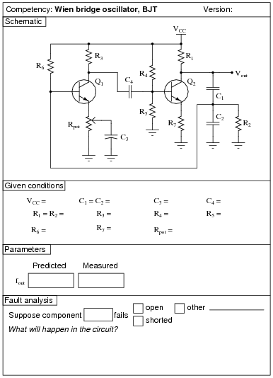
Rpot serves the purpose of providing variable AC gain in the first amplifier stage to meet the Barkhausen criterion.
I have had good success with the following values:
- �
- VCC = 12 volts
- �
- C1 and C2 = 0.001 mF
- �
- C3 = 47 mF
- �
- C4 = 0.47 mF
- �
- R1 and R2 = 4.7 kW
- �
- R3 = 4.7 kW
- �
- R4 = 39 kW
- �
- R5 = 22 kW
- �
- R6 = 27 kW
- �
- R7 = 3.3 kW
- �
- Rpot = 10 kW, linear
- �
- Q1 and Q2 = part number 2N2222
An extension of this exercise is to incorporate troubleshooting questions. Whether using this exercise as a performance assessment or simply as a concept-building lab, you might want to follow up your students' results by asking them to predict the consequences of certain circuit faults.
Question 3:
|
|
Notes:
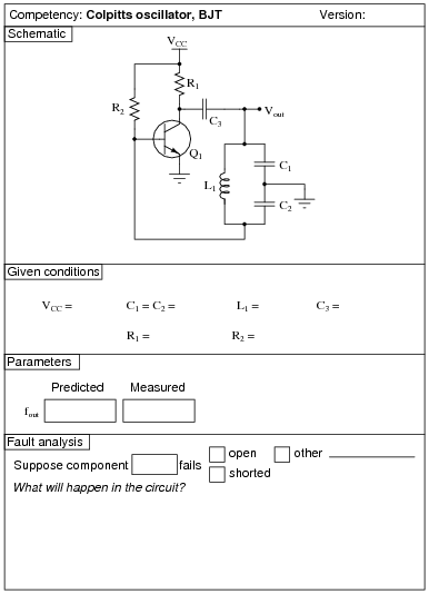
I have had great success with the following values:
- �
- VCC = 7 to 24 volts
- �
- C1 and C2 = 0.22 mF
- �
- C3 = 0.47 mF
- �
- L1 = 100 mH (ferrite core RF choke)
- �
- R1 = 22 kW
- �
- R2 = 1.5 MW
- �
- Q1 = part number 2N3403
With these component values, the output waveform was quite clean and the frequency was very close to predicted:
|
You might want to quiz your students on the purpose of resistor R2, since it usually only has to be present at power-up to initiate oscillation!
An extension of this exercise is to incorporate troubleshooting questions. Whether using this exercise as a performance assessment or simply as a concept-building lab, you might want to follow up your students' results by asking them to predict the consequences of certain circuit faults.
Question 4:
|
|
Notes:
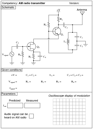
I have had great success with the following values:
- �
- +V = 7 to 24 volts
- �
- C1 and C2 = 0.001 mF
- �
- C3, C4, and C5 = 0.47 mF
- �
- L1 = 100 mH (ferrite core RF choke)
- �
- R1 = 22 kW
- �
- R2 = 1.5 MW
- �
- R3 = 6.8 kW
- �
- R4 = 100 kW
- �
- Q1 = part number 2N3403
- �
- Q2 = part number MPF 102
With these component values, the carrier waveform was quite clean and the frequency was almost exactly 700 kHz:
|
Modulation isn't that great, due to the crude nature of the circuit, but it is certainly good enough to hear over an appropriately tuned AM radio. Setting Vsignal and fsignal is a matter of experimentation, to achieve the desired degree of modulation and tone pitch.
An extension of this exercise is to incorporate troubleshooting questions. Whether using this exercise as a performance assessment or simply as a concept-building lab, you might want to follow up your students' results by asking them to predict the consequences of certain circuit faults.
Question 5:
|
|
Notes:
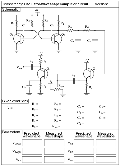
Use a variable-voltage, regulated power supply to supply any amount of DC voltage below 30 volts. Specify standard resistor values, all between 1 kW and 100 kW (1k5, 2k2, 2k7, 3k3, 4k7, 5k1, 6k8, 10k, 22k, 33k, 39k 47k, 68k, etc.).
This circuit demonstrates the use of passive integrators to convert a square wave into a pseudo-sine wave output. The multivibrator portion produces nice, sharp-edged square wave signals at the transistor collector terminals when resistors R1 and R4 are substantially smaller than resistors R2 and R3. Component values I've used with success are 1 kW for R1 and R4, 100 kW for R2 and R3, and 0.001 mF for C1 and C2.
Resistors R5 and R6, along with capacitors C3 and C4, form a dual passive integrator network to re-shape the square-wave output of the multivibrator into a pseudo-sine wave. These components' values must be chosen according to the multivibrator frequency, so that the integration is realistic without the attenuation being excessive. Integrator component values that have worked well for the multivibrator components previously specified are 10 kW for R5 and R6, and 0.1 mF for C3 and C4.
Transistor Q3 is just an emitter follower, placed there to give the amplifier section a high input impedance. Q3's emitter resistor value is not critical. I have used a 1 kW resistor for R7 with good success.
The last transistor (Q4) is for voltage amplification. A "trimmer" style potentiometer (10 kW recommended for Rpot) provides easy adjustment of biasing for different supply voltages. Using the potentiometer, I have operated this circuit on supply voltages ranging from -6 volts to -27 volts. Use a bypass capacitor (C7) large enough that its reactance at the operating frequency is negligible (less than 1 ohm is good), such as 33 mF. Resistor values I've used with success are 10 kW for R8 and 4.7 kW for R9. Coupling capacitor values are not terribly important, so long as they present minimal reactance at the operating frequency. I have used 0.47 mF for both C5 and C6 with good success.
You may find that the relatively high operating frequency of this circuit complicates matters with regard to parasitic capacitances. The fast rise and fall times of the strong square wave tend to couple easily to the sine-wave portions of the circuit, especially when the sine wave signal is so severely attenuated by the double integrators. One solution to this dilemma is to lower the operating frequency of the circuit, allowing a lower cutoff frequency for the double integrator (two-pole lowpass filter) section which in turn will improve the signal-to-noise ratio throughout. If you wish to try this, you may use these suggested component values:
- �
- R1 = 1 kW
- �
- R2 = 100 kW
- �
- R3 = 100 kW
- �
- R4 = 1 kW
- �
- R5 = 100 kW
- �
- R6 = 100 kW
- �
- R7 = 1 kW
- �
- R8 = 10 kW
- �
- R9 = 4.7 kW
- �
- Rpot = 10 kW
- �
- C1 = 0.047 mF
- �
- C2 = 0.047 mF
- �
- C3 = 0.1 mF
- �
- C4 = 0.047 mF
- �
- C5 = 1 mF
- �
- C6 = 1 mF
- �
- C7 = 33 mF
An extension of this exercise is to incorporate troubleshooting questions. Whether using this exercise as a performance assessment or simply as a concept-building lab, you might want to follow up your students' results by asking them to predict the consequences of certain circuit faults.
Question 6:
|
|
Notes:
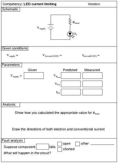
Use a variable-voltage, regulated power supply to supply any amount of DC voltage below 30 volts. Have students calculate the necessary current-limiting resistor for their LEDs based on measured values of Vforward for the LED (using a multimeter with a "diode-check" function). Let students research the typical forward current for their LED from an appropriate datasheet. Any LED should suffice for this activity.
An extension of this exercise is to incorporate troubleshooting questions. Whether using this exercise as a performance assessment or simply as a concept-building lab, you might want to follow up your students' results by asking them to predict the consequences of certain circuit faults.
Question 7:
|
|
Notes:
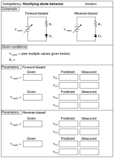
Use a variable-voltage, regulated power supply to supply any amount of DC voltage below 30 volts. Specify standard resistor values, all between 1 kW and 100 kW (1k5, 2k2, 2k7, 3k3, 4k7, 5k1, 6k8, 10k, 22k, 33k, 39k 47k, 68k, etc.). I recommend using one of the 1N400X series of rectifying diodes for their low cost and ruggedness.
An extension of this exercise is to incorporate troubleshooting questions. Whether using this exercise as a performance assessment or simply as a concept-building lab, you might want to follow up your students' results by asking them to predict the consequences of certain circuit faults.
Question 8:
|
|
Notes:
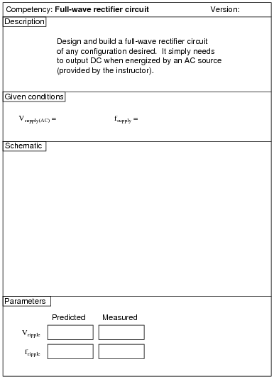
I recommend using 1N400X series rectifying diodes for all rectifier circuit designs. Make sure that the resistance value you specify for your load is not so low that the resistor's power dissipation is exceeded.
Watch out for harmonics in the power line voltage creating problems with RMS/peak voltage relationships. If this is a problem, try using a ferroresonant transformer to filter out some of the harmonic content. Do not try to use a sine-wave signal generator as an alternate source of AC power, because most signal generators have internal impedances that are much too high for such a task.
An extension of this exercise is to incorporate troubleshooting questions. Whether using this exercise as a performance assessment or simply as a concept-building lab, you might want to follow up your students' results by asking them to predict the consequences of certain circuit faults.
Question 9:
|
|
Notes:
I recommend using 1N400X series rectifying diodes for all rectifier circuit designs. Make sure that the resistance value you specify for your load is not so low that the resistor's power dissipation is exceeded.
Watch out for harmonics in the power line voltage creating problems with RMS/peak voltage relationships. If this is a problem, try using a ferroresonant transformer to filter out some of the harmonic content. Do not try to use a sine-wave signal generator as an alternate source of AC power, because most signal generators have internal impedances that are much too high for such a task.
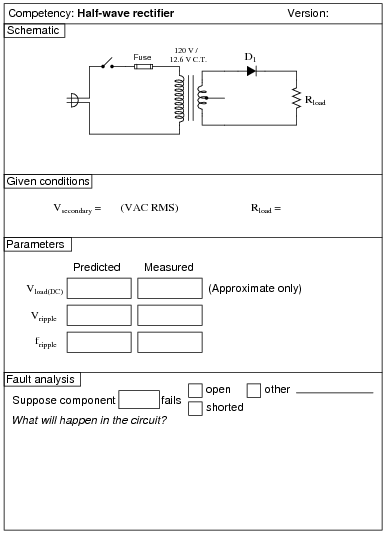
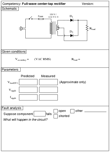
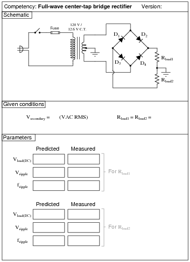
It is difficult to precisely calculate the DC load voltage from a rectifier circuit such as this when the transformer secondary voltage is relatively low. The diodes' forward voltage drop essentially distorts the rectified waveform so that it is not quite the same as what you would expect a full-wave rectified waveform to be:
|
|
Accurate calculation of the actual rectified wave-shape's average voltage value requires integration of the half-sine peak over a period less than p radians, which may very well be beyond the capabilities of your students. This is why I request approximations only on this parameter.
One approximation that works fairly well is to take the AC RMS voltage (in this case, half of the secondary winding's output, since this is a center-tap design), convert it to average voltage (multiply by 0.9), and then subtract the forward junction voltage lost by the diode (0.7 volts typical for silicon).
An extension of this exercise is to incorporate troubleshooting questions. Whether using this exercise as a performance assessment or simply as a concept-building lab, you might want to follow up your students' results by asking them to predict the consequences of certain circuit faults.
Question 10:
|
|
Notes:
I recommend using 1N400X series rectifying diodes for all rectifier circuit designs. Make sure that the resistance value you specify for your load is not so low that the resistor's power dissipation is exceeded.
Watch out for harmonics in the power line voltage creating problems with RMS/peak voltage relationships. If this is a problem, try using a ferroresonant transformer to filter out some of the harmonic content. Do not try to use a sine-wave signal generator as an alternate source of AC power, because most signal generators have internal impedances that are much too high for such a task.
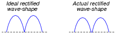
It is difficult to precisely calculate the DC load voltage from a rectifier circuit such as this when the transformer secondary voltage is relatively low. The diodes' forward voltage drop essentially distorts the rectified waveform so that it is not quite the same as what you would expect a full-wave rectified waveform to be:

|
|
Accurate calculation of the actual rectified wave-shape's average voltage value requires integration of the half-sine peak over a period less than p radians, which may very well be beyond the capabilities of your students. This is why I request approximations only on this parameter.
One approximation that works fairly well is to take the AC RMS voltage, convert it to average voltage (multiply by 0.9), and then subtract the total forward junction voltage lost by the diode (0.7 volts per diode typical for silicon, for a total of 1.4 volts).
An extension of this exercise is to incorporate troubleshooting questions. Whether using this exercise as a performance assessment or simply as a concept-building lab, you might want to follow up your students' results by asking them to predict the consequences of certain circuit faults.
Question 11:
|
|
Notes:
I recommend using 1N400X series rectifying diodes for all rectifier circuit designs. Make sure that the resistance value you specify for your load is not so low that the resistor's power dissipation is exceeded.
Watch out for harmonics in the power line voltage creating problems with RMS/peak voltage relationships. If this is a problem, try using a ferroresonant transformer to filter out some of the harmonic content. Do not try to use a sine-wave signal generator as an alternate source of AC power, because most signal generators have internal impedances that are much too high for such a task.
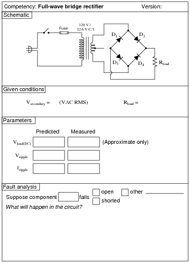
It is difficult to precisely calculate the DC load voltage from a rectifier circuit such as this when the transformer secondary voltage is relatively low. The diodes' forward voltage drop essentially distorts the rectified waveform so that it is not quite the same as what you would expect a full-wave rectified waveform to be:

|
|
Accurate calculation of the actual rectified wave-shape's average voltage value requires integration of the half-sine peak over a period less than p radians, which may very well be beyond the capabilities of your students. This is why I request approximations only on this parameter.
One approximation that works fairly well is to take the AC RMS voltage (in this case, half of the secondary winding's output, since this is a center-tap design), convert it to average voltage (multiply by 0.9), and then subtract the forward junction voltage lost by the diode (0.7 volts typical for silicon).
An extension of this exercise is to incorporate troubleshooting questions. Whether using this exercise as a performance assessment or simply as a concept-building lab, you might want to follow up your students' results by asking them to predict the consequences of certain circuit faults.
Question 12:
|
|
Notes:
I recommend using 1N400X series rectifying diodes for all rectifier circuit designs. Make sure that the resistance value you specify for your load is not so low that the resistor's power dissipation is exceeded.
An extension of this exercise is to incorporate troubleshooting questions. Whether using this exercise as a performance assessment or simply as a concept-building lab, you might want to follow up your students' results by asking them to predict the consequences of certain circuit faults.
Question 13:
|
|
Notes:
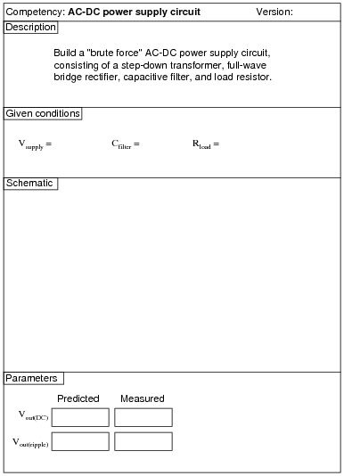
Use a Variac at the test bench to provide variable-voltage AC power for the students' power supply circuits.
An extension of this exercise is to incorporate troubleshooting questions. Whether using this exercise as a performance assessment or simply as a concept-building lab, you might want to follow up your students' results by asking them to predict the consequences of certain circuit faults.
Question 14:
|
|
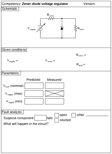
The Vsupply (min) parameter is the minimum voltage setting that Vsupply may be adjusted to with the regulator circuit maintaining constant load voltage at Rload. Vsupply (max) is the maximum voltage that Vsupply may be adjusted to without exceeding the zener diode's power rating. Vload (nominal) is simply the regulated voltage output of the circuit under normal conditions.
Notes:
Use a variable-voltage, regulated power supply to supply any amount of DC voltage below 30 volts. Specify standard load resistor values, all between 1 kW and 100 kW (1k5, 2k2, 2k7, 3k3, 4k7, 5k1, 6k8, 10k, 22k, 33k, 39k 47k, 68k, etc.), and let the students determine the proper resistance values for their series dropping resistors.
I recommend specifying a series resistor value (Rseries) high enough that there will little danger in damaging the zener diode due to excessive supply voltage, but also low enough so that the normal operating current of the zener diode is great enough for it to drop its rated voltage. If Rseries is too large, the zener diode's current will be too small, resulting in lower than expected voltage drop and poorer regulation (operating near the flatter end of the characteristic curve).
Values I have used with success are as follows:
- �
- Rseries = 1 kW
- �
- Rload = 10 kW
- �
- Vzener = 5.1 volts (diode part number 1N4733)
- �
- Vsupply = 12 volts
Measuring the minimum supply voltage is a difficult thing to do, because students must look for a point where the output voltage begins to directly follow the input voltage (going down) instead of holding relatively stable. One interesting way to measure the rate of output voltage change is to set a DMM on the AC voltage setting, then use that to measure Vload as Vsupply is decreased. While turning the voltage adjustment knob on Vsupply at a steady rate, students will look for an increase in AC voltage (a greater rate of change) at Vload. Essentially, what students are looking for is the point where [(dVload)/(dVsupply)] begins to increase.
An extension of this exercise is to incorporate troubleshooting questions. Whether using this exercise as a performance assessment or simply as a concept-building lab, you might want to follow up your students' results by asking them to predict the consequences of certain circuit faults.
Question 15:
|
|
Notes:
I've used 47 mF electrolytic capacitors and 1N4001 diodes with good success on a 10 volt AC (RMS) power supply. I recommend that students measure their own diodes to determine typical forward voltage (VF).
Don't forget to mention the polarity sensitivity of these capacitors! Electrolytic capacitors can explode violently if reverse-connected!
Question 16:
|
|
Notes:
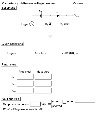
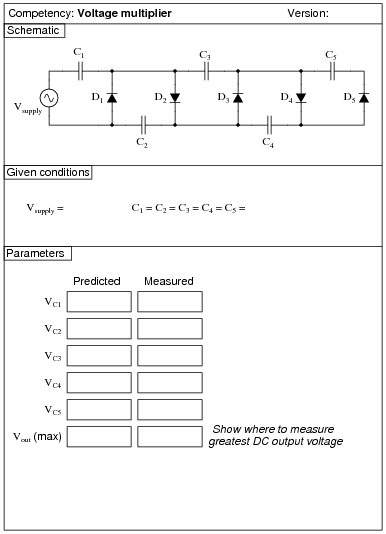
I've used 0.47 mF capacitors and 1N4001 diodes with good success on a 10 volt AC (RMS) power supply. I recommend using low-capacity capacitors to minimize the amount of stored energy, since voltages in this circuit are potentially hazardous.
Question 17:
|
|
Notes:
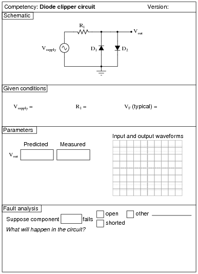
Any diodes will work for this, so long as the source frequency is not too high. I recommend students set the volts/division controls on both channels to the exact same range, so that the slope of the clipped wave near zero-crossing may seen to be exactly the same as the slope of the input sine wave at the same points. This makes it absolutely clear that the output waveform is nothing more than the input waveform with the tops and bottoms cut off.
An extension of this exercise is to incorporate troubleshooting questions. Whether using this exercise as a performance assessment or simply as a concept-building lab, you might want to follow up your students' results by asking them to predict the consequences of certain circuit faults.
Question 18:
|
|
Notes:
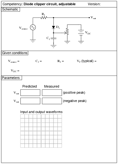
Any diodes will work for this, so long as the source frequency is not too high.
I have had good success with the following values:
- �
- Vsource = 4 volts (peak)
- �
- fsource = 3 kHz
- �
- VDC = 6 volts
- �
- C1 = 0.47 mF
- �
- R1 = 100 kW
- �
- Potentiometer = 10 kW, linear
- �
- D1 = part number 1N4004 (any 1N400x diode should work)
An extension of this exercise is to incorporate troubleshooting questions. Whether using this exercise as a performance assessment or simply as a concept-building lab, you might want to follow up your students' results by asking them to predict the consequences of certain circuit faults.
Question 19:
|
|
Notes:
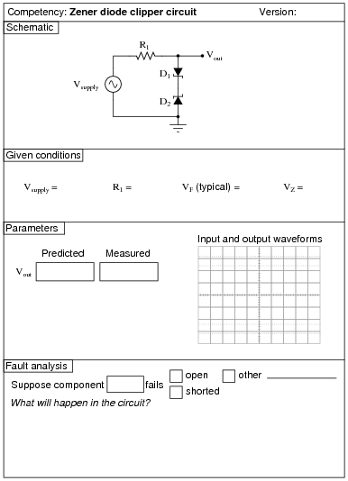
Be sure to use zener diodes with reasonably low breakdown voltages, and specify the source voltage accordingly.
An extension of this exercise is to incorporate troubleshooting questions. Whether using this exercise as a performance assessment or simply as a concept-building lab, you might want to follow up your students' results by asking them to predict the consequences of certain circuit faults.
Question 20:
|
|
Notes:
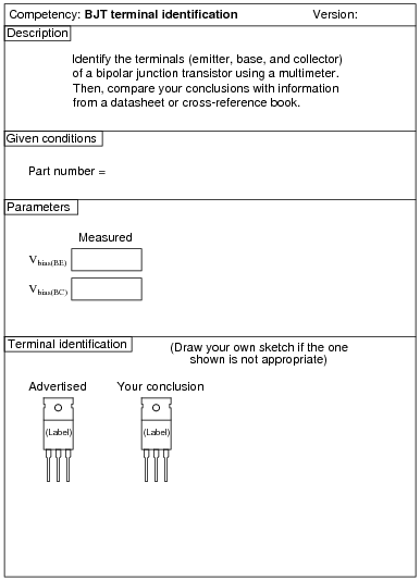
Identification of BJT terminals is a very important skill for technicians to have. Most modern multimeters have a diode check feature which may be used to positively identify PN junction polarities, and this is what I recommend students use for identifying BJT terminals.
To make this a really good performance assessment, you might want to take several BJT's and scratch the identifying labels off, so students cannot refer to memory for pin identification (for instance, if they remember the pin assignments of a 2N2222 because they use it so often). Label these transistors with your own numbers ("1", "2", etc.) so you will know which is which, but not the students!
Question 21:
|
|
Notes:
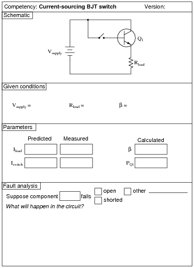
Being able to design a circuit using a BJT as a switch is a valuable skill for technicians and engineers alike to have. The circuit shown in this question is not the only possibility, but it is the simplest.
Remind your students that the equation for calculating BJT power dissipation is as follows:
|
An extension of this exercise is to incorporate troubleshooting questions. Whether using this exercise as a performance assessment or simply as a concept-building lab, you might want to follow up your students' results by asking them to predict the consequences of certain circuit faults.
Question 22:
|
|
Notes:
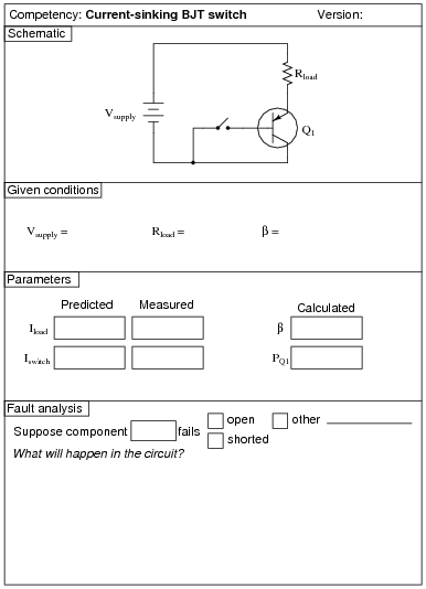
Being able to design a circuit using a BJT as a switch is a valuable skill for technicians and engineers alike to have. The circuit shown in this question is not the only possibility, but it is the simplest.
Remind your students that the equation for calculating BJT power dissipation is as follows:
|
An extension of this exercise is to incorporate troubleshooting questions. Whether using this exercise as a performance assessment or simply as a concept-building lab, you might want to follow up your students' results by asking them to predict the consequences of certain circuit faults.
Question 23:
|
|
Notes:
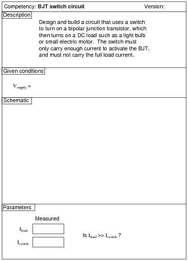
Being able to design a circuit using a BJT as a switch is a valuable skill for technicians and engineers alike to have.
An extension of this exercise is to incorporate troubleshooting questions. Whether using this exercise as a performance assessment or simply as a concept-building lab, you might want to follow up your students' results by asking them to predict the consequences of certain circuit faults.
Question 24:
|
|
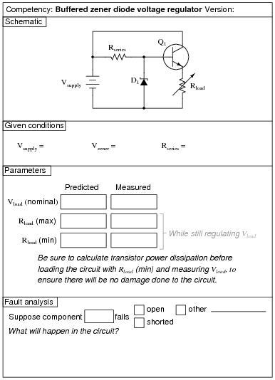
The Rload (max) and Rload (min) parameters are the maximum and minimum resistance settings that Rload may be adjusted to with the regulator circuit maintaining constant load voltage. Vload (nominal) is simply the regulated voltage output of the circuit under normal conditions.
Notes:
Use a variable-voltage, regulated power supply to supply any amount of DC voltage below 30 volts.
I highly recommend specifying a large value for Rseries and/or a high-wattage rated transistor and variable load resistor, so that students do not dissipate excessive power at either the transistor or the load as they test for Rload (min). Do not use a decade resistance box for Rload unless you have made sure its power dissipation will not be exceeded under any circuit condition!
An extension of this exercise is to incorporate troubleshooting questions. Whether using this exercise as a performance assessment or simply as a concept-building lab, you might want to follow up your students' results by asking them to predict the consequences of certain circuit faults.
Question 25:
|
|
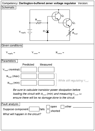
The Rload (max) and Rload (min) parameters are the maximum and minimum resistance settings that Rload may be adjusted to with the regulator circuit maintaining constant load voltage. Vload (nominal) is simply the regulated voltage output of the circuit under normal conditions.
Notes:
Use a variable-voltage, regulated power supply to supply any amount of DC voltage below 30 volts.
I highly recommend specifying a large value for Rseries and/or a high-wattage rated transistor and variable load resistor, so that students do not dissipate excessive power at either the transistor or the load as they test for Rload (min). Do not use a decade resistance box for Rload unless you have made sure its power dissipation will not be exceeded under any circuit condition!
An extension of this exercise is to incorporate troubleshooting questions. Whether using this exercise as a performance assessment or simply as a concept-building lab, you might want to follow up your students' results by asking them to predict the consequences of certain circuit faults.
Question 26:
|
|
Notes:
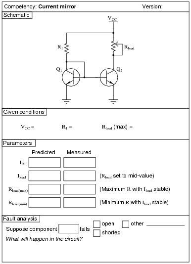
I recommend a 47 kW resistor for R1 and a 100 kW potentiometer for Rload.
An extension of this exercise is to incorporate troubleshooting questions. Whether using this exercise as a performance assessment or simply as a concept-building lab, you might want to follow up your students' results by asking them to predict the consequences of certain circuit faults.
Question 27:
|
|
Notes:
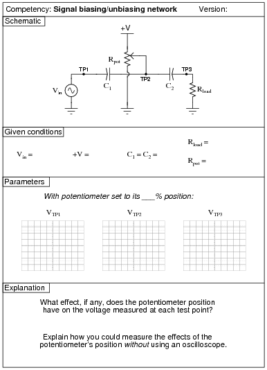
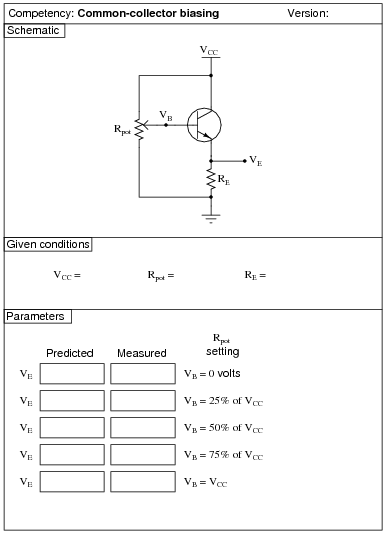
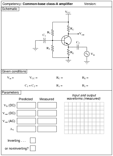
The purpose of this exercise is to get students to understand how AC signals are mixed with DC voltages ("biased") and also how these DC bias voltages are removed to leave just an AC signal. This is important to understand for the purpose of analyzing BJT amplifier circuits.
Use a variable-voltage, regulated power supply to supply any amount of DC voltage below 30 volts. Specify standard resistor values, all between 1 kW and 100 kW (1k5, 2k2, 2k7, 3k3, 4k7, 5k1, 6k8, 10k, 22k, 33k, 39k 47k, 68k, etc.). Use a sine-wave function generator to supply an audio-frequency input signal.
An extension of this exercise is to incorporate troubleshooting questions. Whether using this exercise as a performance assessment or simply as a concept-building lab, you might want to follow up your students' results by asking them to predict the consequences of certain circuit faults.
Question 28:
|
|
Notes:
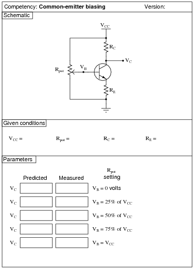
Use a variable-voltage, regulated power supply to supply any amount of DC voltage below 30 volts. Specify standard resistor values, all between 1 kW and 100 kW (1k5, 2k2, 2k7, 3k3, 4k7, 5k1, 6k8, 10k, 22k, 33k, 39k 47k, 68k, etc.).
Question 29:
|
|
Notes:
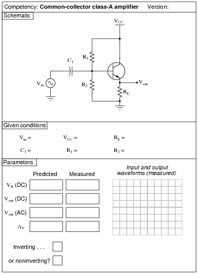
Use a variable-voltage, regulated power supply to supply any amount of DC voltage below 30 volts. Specify standard resistor values, all between 1 kW and 100 kW (1k5, 2k2, 2k7, 3k3, 4k7, 5k1, 6k8, 10k, 22k, 33k, 39k 47k, 68k, etc.). Use a sine-wave function generator to supply an audio-frequency input signal, and make sure its amplitude isn't set so high that the amplifier clips.
I have had good success using the following values:
- �
- VCC = 9 volts
- �
- Vin = 1 volt RMS, audio frequency
- �
- R1 = 10 kW
- �
- R2 = 10 kW
- �
- RE = 27 kW
- �
- C1 = 10 mF
An extension of this exercise is to incorporate troubleshooting questions. Whether using this exercise as a performance assessment or simply as a concept-building lab, you might want to follow up your students' results by asking them to predict the consequences of certain circuit faults.
Question 30:
|
|
Notes:
Use a variable-voltage, regulated power supply to supply any amount of DC voltage below 30 volts. Specify standard resistor values, all between 1 kW and 100 kW (1k5, 2k2, 2k7, 3k3, 4k7, 5k1, 6k8, 10k, 22k, 33k, 39k 47k, 68k, etc.).
Question 31:
|
|
Notes:
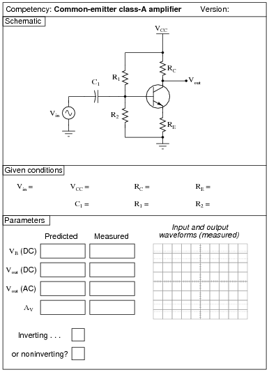
Use a variable-voltage, regulated power supply to supply any amount of DC voltage below 30 volts. Specify standard resistor values, all between 1 kW and 100 kW (1k5, 2k2, 2k7, 3k3, 4k7, 5k1, 6k8, 10k, 22k, 33k, 39k 47k, 68k, etc.). Use a sine-wave function generator to supply an audio-frequency input signal, and make sure its amplitude isn't set so high that the amplifier clips.
I have had good success using the following values:
- �
- VCC = 9 volts
- �
- Vin = audio-frequency signal, 0.5 volt peak-to-peak
- �
- R1 = 220 kW
- �
- R2 = 27 kW
- �
- RC = 10 kW
- �
- RE = 1.5 kW
- �
- C1 = 10 mF
An extension of this exercise is to incorporate troubleshooting questions. Whether using this exercise as a performance assessment or simply as a concept-building lab, you might want to follow up your students' results by asking them to predict the consequences of certain circuit faults.
Question 32:
|
|
Notes:
Use a variable-voltage, regulated power supply to supply any amount of DC voltage below 30 volts. Specify standard resistor values, all between 1 kW and 100 kW (1k5, 2k2, 2k7, 3k3, 4k7, 5k1, 6k8, 10k, 22k, 33k, 39k 47k, 68k, etc.). Use a sine-wave function generator to supply an audio-frequency input signal, and make sure its amplitude isn't set so high that the amplifier clips.
The voltage gain of this amplifier configuration tends to be very high, approximately equal to [(RC)/(r�e)]. Your students will have to use fairly low input voltages to achieve class A operation with this amplifier circuit. I have had good success using the following values:
- �
- VCC = 12 volts
- �
- Vin = 20 mV peak-to-peak, at 5 kHz
- �
- R1 = 1 kW
- �
- R2 = 4.7 kW
- �
- RC = 100 W
- �
- RE = 1 kW
- �
- C1 = 33 mF
Your students will find the actual voltage gain deviates somewhat from predicted values with this circuit, largely because it is so dependent on the value of r�e, and that parameter tends to be unpredictable.
An extension of this exercise is to incorporate troubleshooting questions. Whether using this exercise as a performance assessment or simply as a concept-building lab, you might want to follow up your students' results by asking them to predict the consequences of certain circuit faults.
Question 33:
|
|
Notes:
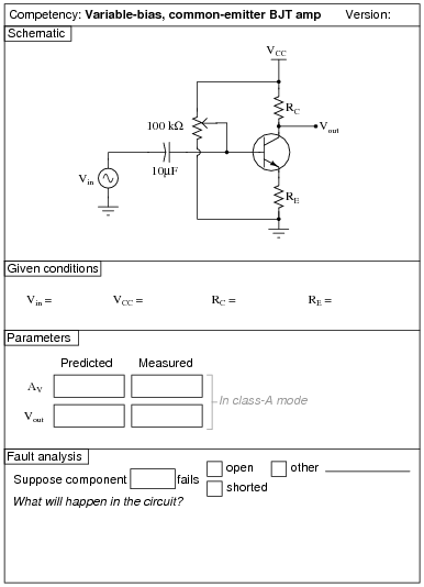
Use a variable-voltage, regulated power supply to supply any amount of DC voltage below 30 volts. Specify standard resistor values, all between 1 kW and 100 kW (1k5, 2k2, 2k7, 3k3, 4k7, 5k1, 6k8, 10k, 22k, 33k, 39k 47k, 68k, etc.). Use a sine-wave function generator to supply an audio-frequency input signal, about 0.5 volts AC (peak).
Resistor values I have found practical are 10 kW for RC and 2.2 kW for RE. This gives a voltage gain of 4.545, and quiescent current values that are well within the range of common small-signal transistors.
An important aspect of this performance assessment is that students know what to do with the potentiometer. It is their responsibility to configure the circuit so that it operates in Class-A mode, and to explain the importance of proper biasing.
An extension of this exercise is to incorporate troubleshooting questions. Whether using this exercise as a performance assessment or simply as a concept-building lab, you might want to follow up your students' results by asking them to predict the consequences of certain circuit faults.
Question 34:
|
|
Notes:
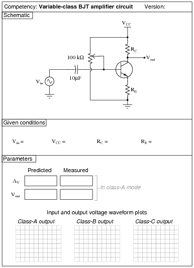
Use a variable-voltage, regulated power supply to supply any amount of DC voltage below 30 volts. Specify standard resistor values, all between 1 kW and 100 kW (1k5, 2k2, 2k7, 3k3, 4k7, 5k1, 6k8, 10k, 22k, 33k, 39k 47k, 68k, etc.). Use a sine-wave function generator to supply an audio-frequency input signal, about 0.5 volts AC (peak).
Resistor values I have found practical are 10 kW for RC and 2.2 kW for RE. This gives a voltage gain of 4.545, and quiescent current values that are well within the range of common small-signal transistors.
An important aspect of this performance assessment is that students know what to do with the potentiometer. It is their responsibility to configure the circuit so that it operates in each mode (Class-A, Class-B, and Class-C).
An extension of this exercise is to incorporate troubleshooting questions. Whether using this exercise as a performance assessment or simply as a concept-building lab, you might want to follow up your students' results by asking them to predict the consequences of certain circuit faults.
Question 35:
|
|
Notes:
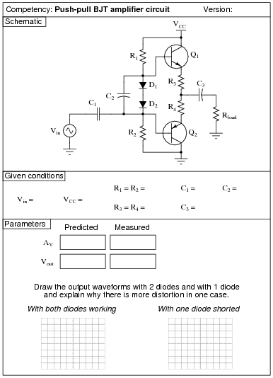
Use a variable-voltage, regulated power supply to supply any amount of DC voltage below 30 volts. Specify standard resistor values, all between 1 kW and 100 kW (1k5, 2k2, 2k7, 3k3, 4k7, 5k1, 6k8, 10k, 22k, 33k, 39k 47k, 68k, etc.). Use a sine-wave function generator to supply an audio-frequency input signal, and make sure its amplitude isn't set so high that the amplifier clips.
I have had good success using the following values:
- �
- VCC = 6 volts
- �
- Vin = 1 volt (peak)
- �
- R1 = R2 = 10 kW
- �
- R3 = R4 = 10 W
- �
- C1 = 0.47 mF
- �
- C2 = 10 mF
- �
- C3 = 47 mF
- �
- D1 = D2 = part number 1N4001
- �
- Q1 = part number 2N2222
- �
- Q2 = part number 2N2907
An extension of this exercise is to incorporate troubleshooting questions. Whether using this exercise as a performance assessment or simply as a concept-building lab, you might want to follow up your students' results by asking them to predict the consequences of certain circuit faults.
Question 36:
|
|
Notes:
I've experienced good results using the following component values:
- �
- VCC = 12 volts
- �
- R1 = 220 kW
- �
- R2 = 27 kW
- �
- R3 = 10 kW
- �
- R4 = 1.5 kW
- �
- R5 = 1 kW
- �
- C1 = 0.47 mF
- �
- C2 = 4.7 mF
- �
- C3 = 33 mF
- �
- C4 = 47 mF
- �
- Q1 and Q2 = 2N3403
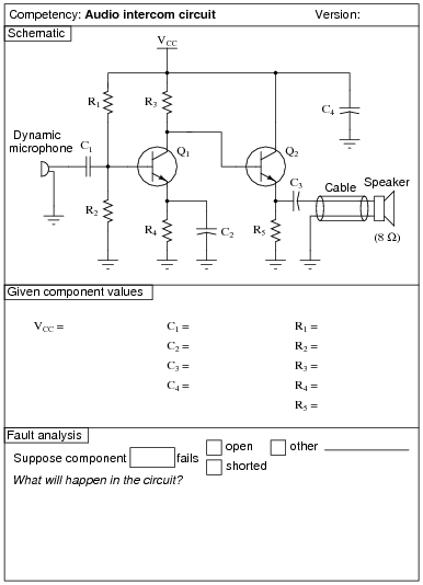
Students have a lot of fun connecting long lengths of cable between the output stage and the speaker, and using this circuit to talk (one-way, simplex communication) between rooms.
One thing I've noticed some students misunderstand in their study of electronic amplifier circuits is their practical purpose. So many textbooks emphasize abstract analysis with sinusoidal voltage sources and resistive loads that some of the real applications of amplifiers may be overlooked by some students. One student of mine in particular, when building this circuit, kept asking me, ßo where does the signal generator connect to this amplifier?" He was so used to seeing signal generators connected to amplifier inputs in his textbook (and lab manual!) that he never realized you could use an amplifier circuit to amplify a real, practical audio signal!!! An extreme example, perhaps, but real nevertheless, and illustrative of the need for practical application in labwork.
In order for students to measure the voltage gain of this amplifier, they must apply a steady, sinusoidal signal to the input. The microphone and speaker are indeed practical, but the signals produced in such a circuit are too chaotic for students to measure with simple test equipment.
An extension of this exercise is to incorporate troubleshooting questions. Whether using this exercise as a performance assessment or simply as a concept-building lab, you might want to follow up your students' results by asking them to predict the consequences of certain circuit faults.
Question 37:
|
|
Notes:
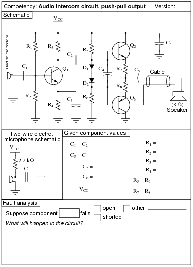
Use a variable-voltage, regulated power supply to supply a DC voltage safely below the maximum rating of the electret microphone (typically 10 volts). Specify standard resistor values, all between 1 kW and 100 kW (1k5, 2k2, 2k7, 3k3, 4k7, 5k1, 6k8, 10k, 22k, 33k, 39k 47k, 68k, etc.). Use a sine-wave function generator to supply an audio-frequency input signal, and make sure its amplitude isn't set so high that the amplifier clips.
I have had good success using the following values:
- �
- VCC = 6 volts
- �
- R1 = 68 kW
- �
- R2 = 33 kW
- �
- R3 = 4.7 kW
- �
- R4 = 1.5 kW
- �
- R5 = R6 = 10 kW
- �
- R7 = R8 = 10 W
- �
- C1 = C2 = 0.47 mF
- �
- C3 = C4 = 47 mF
- �
- C5 = 1000 mF
- �
- C6 = 100 mF
- �
- D1 = D2 = part number 1N4001
- �
- Q1 = part number 2N2222
- �
- Q2 = part number 2N2222
- �
- Q3 = part number 2N2907
An extension of this exercise is to incorporate troubleshooting questions. Whether using this exercise as a performance assessment or simply as a concept-building lab, you might want to follow up your students' results by asking them to predict the consequences of certain circuit faults.
Question 38:
|
|
Notes:
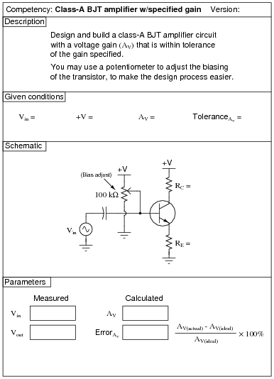
Students are allowed to adjust the bias potentiometer to achieve class-A operation after calculating and inserting the resistance values RC and RE. However, they are not allowed to change either RC or RE once the circuit is powered and tested, lest they achieve the specified gain through trial-and-error!
A good percentage tolerance for gain is +/- 10%. The lower you set the target gain, the more accuracy you may expect out of your students' circuits. I usually select random values of voltage gain between 2 and 10, and I strongly recommend that students choose resistor values between 1 kW and 100 kW. Resistor values much lower than 1 kW lead to excessive quiescent currents, which may cause accuracy problems (r�e drifting due to temperature effects).
An extension of this exercise is to incorporate troubleshooting questions. Whether using this exercise as a performance assessment or simply as a concept-building lab, you might want to follow up your students' results by asking them to predict the consequences of certain circuit faults.
Question 39:
|
|
Notes:
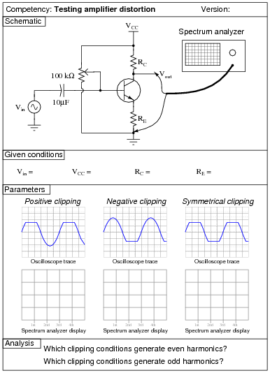
Use a variable-voltage, regulated power supply to supply any amount of DC voltage below 30 volts. Specify standard resistor values, all between 1 kW and 100 kW (1k5, 2k2, 2k7, 3k3, 4k7, 5k1, 6k8, 10k, 22k, 33k, 39k 47k, 68k, etc.). Use a sine-wave function generator to supply an audio-frequency input signal.
If you lack a spectrum analyzer in your lab, fear not! There are free software packages in existence allowing you to use the audio input of a personal computer's sound card as a (limited) spectrum analyzer and oscilloscope! You may find some of these packages by searching on the Internet. One that I've used (2002) successfully in my own class is called WinScope.
An extension of this exercise is to incorporate troubleshooting questions. Whether using this exercise as a performance assessment or simply as a concept-building lab, you might want to follow up your students' results by asking them to predict the consequences of certain circuit faults.
Question 40:
|
|
Notes:
Use a variable-voltage, regulated power supply to supply any amount of DC voltage below 30 volts. Specify standard resistor values, all between 1 kW and 100 kW (1k5, 2k2, 2k7, 3k3, 4k7, 5k1, 6k8, 10k, 22k, 33k, 39k 47k, 68k, etc.).
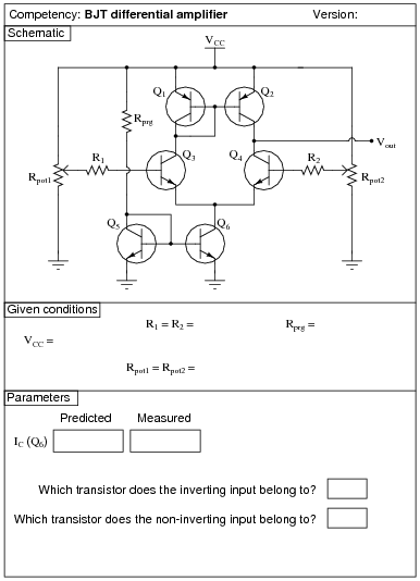
I suggest using ordinary (general-purpose) signal transistors in this circuit, such as the 2N2222 and 2N3403 (NPN), and the 2N2907 and 2N3906 (PNP) models, operating with a VCC of 12 volts. When constructed as shown, this circuit has sufficient gain to be used as a crude operational amplifier (connect the inverting input to the output through various feedback networks).
These values have worked well for me:
- �
- VCC = 12 volts
- �
- R1 = 10 kW
- �
- R2 = 10 kW
- �
- Rprg = 10 kW
- �
- Rpot1 = 10 kW
- �
- Rpot2 = 10 kW
I recommend instructing students to set each potentiometer near its mid-position of travel, then slightly adjusting each one to see the sharp change in output voltage as one input voltage crosses the other. If students wish to monitor each of the input voltages to check for a condition of crossing, they should measure right at the transistor base terminals, not at the potentiometer wiper terminals, so as to not incur error resulting from current through protection resistors R1 or R2.
An extension of this exercise is to incorporate troubleshooting questions. Whether using this exercise as a performance assessment or simply as a concept-building lab, you might want to follow up your students' results by asking them to predict the consequences of certain circuit faults.
Question 41:
|
|
Notes:
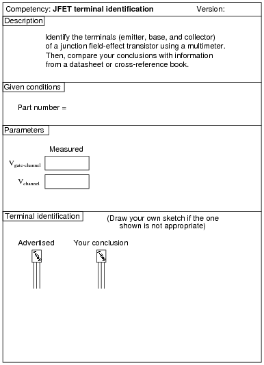
Identification of JFET terminals is a very important skill for technicians to have. Most modern multimeters have a diode check feature which may be used to positively identify PN junction polarities, and this is what I recommend students use for identifying JFET terminals.
To make this a really good performance assessment, you might want to take several JFET's and scratch the identifying labels off, so students cannot refer to memory for pin identification (for instance, if they remember the pin assignments of a J309 because they use it so often). Label these transistors with your own numbers ("1", "2", etc.) so you will know which is which, but not the students!
Question 42:
|
|
Notes:
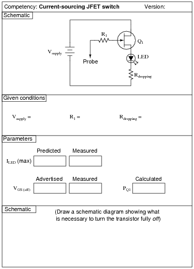
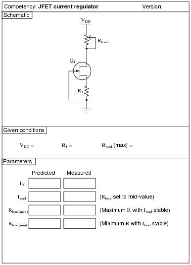
I strongly recommend a value for R1 of 1 MW or more, to protect the JFET gate from overcurrent damage. The students will calculate their own dropping resistor value, based on the supply voltage and the LED ratings.
This exercise lends itself to experimentation with static electricity. The input impedance of an average JFET is so high that the LED may be made to turn on and off with just a touch of the probe wire to a charged object (such as a person).
Using only the components shown, students may not be able to get their JFETs to completely turn off. This is left for them as a challenge to figure out!
I expect students to be able to figure out how to calculate the transistor's power dissipation without being told what measurements to take!
Question 43:
|
|
Notes:
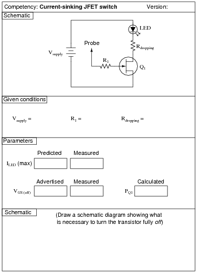
I strongly recommend a value for R1 of 1 MW or more, to protect the JFET gate from overcurrent damage. The students will calculate their own dropping resistor value, based on the supply voltage and the LED ratings.
This exercise lends itself to experimentation with static electricity. The input impedance of an average JFET is so high that the LED may be made to turn on and off with just a touch of the probe wire to a charged object (such as a person).
Using only the components shown, students may not be able to get their JFETs to completely turn off. This is left for them as a challenge to figure out!
I expect students to be able to figure out how to calculate the transistor's power dissipation without being told what measurements to take!
Question 44:
|
|
Notes:
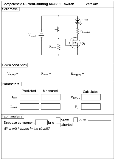
I recommend a value for R1 of 1 MW or more, to show that the bleed resistor need not be very conductive to do its job well. The students will calculate their own dropping resistor value, based on the supply voltage and the LED ratings.
Students predict the LED current (approximately 20 mA) and the switch current (0 mA), and then calculate the transistor's ön" channel resistance and power dissipation after taking additional measurements. I expect students to be able to figure out how to calculate both these parameters without being told what measurements to take!
Question 45:
|
|
Notes:
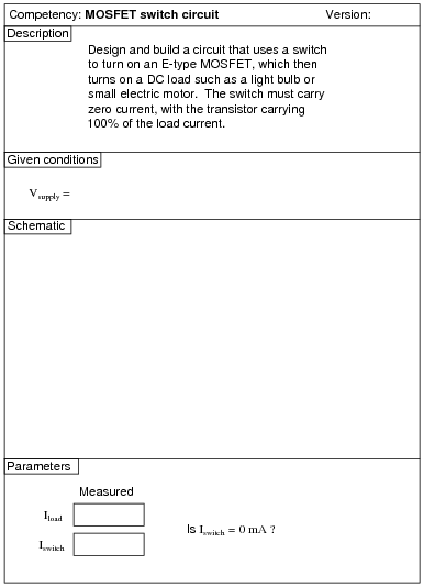
Being able to design a circuit using a MOSFET as a switch is a valuable skill for technicians and engineers alike to have.
An extension of this exercise is to incorporate troubleshooting questions. Whether using this exercise as a performance assessment or simply as a concept-building lab, you might want to follow up your students' results by asking them to predict the consequences of certain circuit faults.
Question 46:
|
|
Notes:
An extension of this exercise is to incorporate troubleshooting questions. Whether using this exercise as a performance assessment or simply as a concept-building lab, you might want to follow up your students' results by asking them to predict the consequences of certain circuit faults.
Question 47:
|
|
Notes:
Use a variable-voltage, regulated power supply to supply any amount of DC voltage below 30 volts. Specify standard resistor values, all between 1 kW and 100 kW (1k5, 2k2, 2k7, 3k3, 4k7, 5k1, 6k8, 10k, 22k, 33k, 39k 47k, 68k, etc.). Use a sine-wave function generator to supply an audio-frequency input signal, and make sure its amplitude isn't set so high that the amplifier clips.
I have had good success using the following values:
- �
- VDD = 9 volts
- �
- Vin = 1 volt (peak), f = 2 kHz
- �
- RG = 100 kW
- �
- RS = 10 kW
- �
- C1 = 0.47 mF
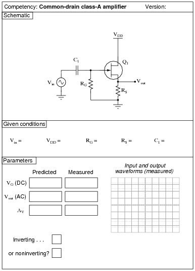
Please note that the quiescent output voltage is impossible to precisely predict, as it depends on the particular characteristics of the JFET used (ID versus VGS). The fact that this circuit uses self-biasing instead of voltage divider biasing makes the situation worse. Predicting quiescent gate voltage, however should be extremely easy (0 volts) if one understands how JFETs function.
An interesting parameter to explore in this circuit is the effect of the source resistor value on voltage gain. The theoretical voltage gain of a simple common-drain amplifier circuit is unity (1), but this may be approximated only with relatively large load resistor (RS) values. Try substituting a 1 kW or less resistor for RS, and notice what happens to the gain. Then, have your students explain why this happens!
An extension of this exercise is to incorporate troubleshooting questions. Whether using this exercise as a performance assessment or simply as a concept-building lab, you might want to follow up your students' results by asking them to predict the consequences of certain circuit faults.
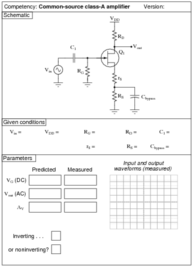
Question 48:
|
|
Notes:
Use a variable-voltage, regulated power supply to supply any amount of DC voltage below 30 volts. Specify standard resistor values, all between 1 kW and 100 kW (1k5, 2k2, 2k7, 3k3, 4k7, 5k1, 6k8, 10k, 22k, 33k, 39k 47k, 68k, etc.). Use a sine-wave function generator to supply an audio-frequency input signal, and make sure its amplitude isn't set so high that the amplifier clips.
I have had good success using the following values:
- �
- VDD = 12 volts
- �
- Vin = 0.5 volt (peak-to-peak), f = 2 kHz
- �
- RG = 100 kW
- �
- rS = 2.2 kW
- �
- RS = 10 kW
- �
- RD = 10 kW
- �
- C1 = 0.47 mF
- �
- Cbypass = 10 mF
Please note that the quiescent output voltage is impossible to precisely predict, as it depends on the particular characteristics of the JFET used (ID versus VGS). The fact that this circuit uses self-biasing instead of voltage divider biasing makes the situation worse. Predicting quiescent gate voltage, however should be extremely easy (0 volts) if one understands how JFETs function.
All quiescent circuit values depend on VDD, so if things aren't biased the way you would like, simply adjust the power supply voltage to suit.
An extension of this exercise is to incorporate troubleshooting questions. Whether using this exercise as a performance assessment or simply as a concept-building lab, you might want to follow up your students' results by asking them to predict the consequences of certain circuit faults.
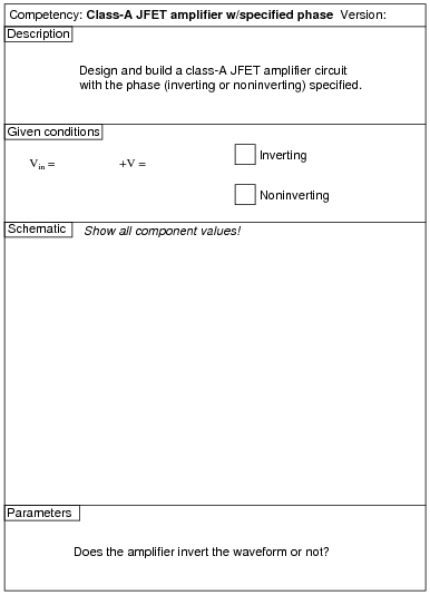
Question 49:
|
|
Notes:
Use a variable-voltage, regulated power supply to supply any amount of DC voltage below 30 volts. Specify standard resistor values, all between 1 kW and 100 kW (1k5, 2k2, 2k7, 3k3, 4k7, 5k1, 6k8, 10k, 22k, 33k, 39k 47k, 68k, etc.). Use a sine-wave function generator to supply an audio-frequency input signal, and make sure its amplitude isn't set so high that the amplifier clips.
An extension of this exercise is to incorporate troubleshooting questions. Whether using this exercise as a performance assessment or simply as a concept-building lab, you might want to follow up your students' results by asking them to predict the consequences of certain circuit faults.
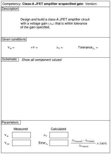
Question 50:
|
|
Notes:
Use a variable-voltage, regulated power supply to supply any amount of DC voltage below 30 volts. Specify standard resistor values, all between 1 kW and 100 kW (1k5, 2k2, 2k7, 3k3, 4k7, 5k1, 6k8, 10k, 22k, 33k, 39k 47k, 68k, etc.). Use a sine-wave function generator to supply an audio-frequency input signal, and make sure its amplitude isn't set so high that the amplifier clips at the specified gain.
An extension of this exercise is to incorporate troubleshooting questions. Whether using this exercise as a performance assessment or simply as a concept-building lab, you might want to follow up your students' results by asking them to predict the consequences of certain circuit faults.
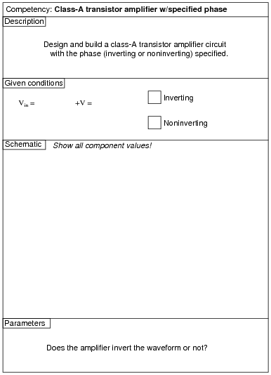
Question 51:
|
|
Notes:
Use a variable-voltage, regulated power supply to supply any amount of DC voltage below 30 volts. Specify standard resistor values, all between 1 kW and 100 kW (1k5, 2k2, 2k7, 3k3, 4k7, 5k1, 6k8, 10k, 22k, 33k, 39k 47k, 68k, etc.). Use a sine-wave function generator to supply an audio-frequency input signal, and make sure its amplitude isn't set so high that the amplifier clips.
An extension of this exercise is to incorporate troubleshooting questions. Whether using this exercise as a performance assessment or simply as a concept-building lab, you might want to follow up your students' results by asking them to predict the consequences of certain circuit faults.
Question 52:
|
|
Notes:
Use a variable-voltage, regulated power supply to supply any amount of DC voltage below 30 volts. Specify standard resistor values, all between 1 kW and 100 kW (1k5, 2k2, 2k7, 3k3, 4k7, 5k1, 6k8, 10k, 22k, 33k, 39k 47k, 68k, etc.).
This circuit produces nice, sharp-edged square wave signals at the transistor collector terminals when resistors R1 and R4 are substantially smaller than resistors R2 and R3. This way, R2 and R3 dominate the capacitors' charging times, making calculation of duty cycle much more accurate. Component values I've used with success are 470 W for R1 and R2, 270 kW for R2 and R3, 4.7 mF for C1 and C2, and 6 to 14 volts for VCC. The frequency of this circuit does vary with supply voltage, so don't expect perfect agreement between predicted and measured values.
By the way, this circuit works very well for holiday flashing lights - decorate your lab room accordingly with student-built light flashers!
An extension of this exercise is to incorporate troubleshooting questions. Whether using this exercise as a performance assessment or simply as a concept-building lab, you might want to follow up your students' results by asking them to predict the consequences of certain circuit faults.
Question 53:
|
|
Notes:
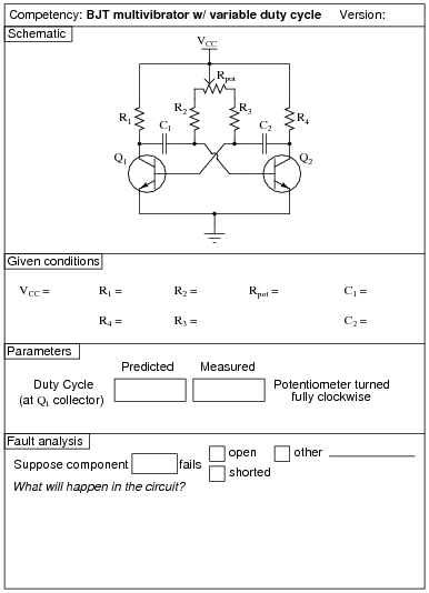
Use a variable-voltage, regulated power supply to supply any amount of DC voltage below 30 volts. Specify standard resistor values, all between 1 kW and 100 kW (1k5, 2k2, 2k7, 3k3, 4k7, 5k1, 6k8, 10k, 22k, 33k, 39k 47k, 68k, etc.).
This circuit produces nice, sharp-edged square wave signals at the transistor collector terminals when resistors R1 and R4 are substantially smaller than the combined resistance of resistors R2 and R3 and the respective potentiometer section resistances. This way, Rpot, R2, and R3 dominate the capacitors' charging times, making calculation of duty cycle much more accurate. Component values I've used with success are 1 kW for R1 and R2, 10 kW for R2 and R3, 100 kW for Rpot, and 0.001 mF for C1 and C2.
An extension of this exercise is to incorporate troubleshooting questions. Whether using this exercise as a performance assessment or simply as a concept-building lab, you might want to follow up your students' results by asking them to predict the consequences of certain circuit faults.
Question 54:
|
|
Notes:
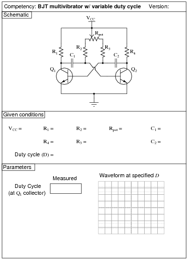
Use a variable-voltage, regulated power supply to supply any amount of DC voltage below 30 volts. Specify standard resistor values, all between 1 kW and 100 kW (1k5, 2k2, 2k7, 3k3, 4k7, 5k1, 6k8, 10k, 22k, 33k, 39k 47k, 68k, etc.).
This circuit produces nice, sharp-edged square wave signals at the transistor collector terminals when resistors R1 and R4 are substantially smaller than the combined resistance of resistors R2 and R3 and the respective potentiometer section resistances. This way, Rpot, R2, and R3 dominate the capacitors' charging times, making calculation of duty cycle much more accurate. Component values I've used with success are 1 kW for R1 and R2, 10 kW for R2 and R3, 100 kW for Rpot, and 0.001 mF for C1 and C2.
An extension of this exercise is to incorporate troubleshooting questions. Whether using this exercise as a performance assessment or simply as a concept-building lab, you might want to follow up your students' results by asking them to predict the consequences of certain circuit faults.
Question 55:
|
|
Notes:
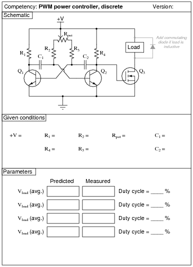
Use a variable-voltage, regulated power supply to supply any amount of DC voltage below 30 volts. Specify standard resistor values, all between 1 kW and 100 kW (1k5, 2k2, 2k7, 3k3, 4k7, 5k1, 6k8, 10k, 22k, 33k, 39k 47k, 68k, etc.).
This circuit produces nice, sharp-edged square wave signals at the transistor collector terminals when resistors R1 and R4 are substantially smaller than the combined resistance of resistors R2 and R3 and the respective potentiometer section resistances. This way, Rpot, R2, and R3 dominate the capacitors' charging times, making calculation of duty cycle much more accurate. Component values I've used with success are 1 kW for R1 and R4, 10 kW for R2 and R3, 100 kW for Rpot, and 0.001 mF for C1 and C2. In my prototype circuit, I used 2N2222 bipolar transistors and an IRF510 power MOSFET.
Although small DC motors work well as demonstrative loads, their counter-EMF may wreak havoc with measurements of average load voltage. Purely resistive loads work best when comparing measured average load voltage against predicted average load voltage. Also, motors and other inductive loads may cause the MOSFET to switch incorrectly (or not switch at all!) unless a commutating diode is installed to limit the voltage induced by the collapsing magnetic field every time the transistor turns off.
An extension of this exercise is to incorporate troubleshooting questions. Whether using this exercise as a performance assessment or simply as a concept-building lab, you might want to follow up your students' results by asking them to predict the consequences of certain circuit faults.
Question 56:
|
|
Notes:
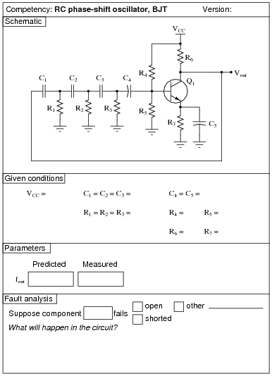
Use a variable-voltage, regulated power supply to supply any amount of DC voltage below 30 volts. Specify standard resistor values, all between 1 kW and 100 kW (1k5, 2k2, 2k7, 3k3, 4k7, 5k1, 6k8, 10k, 22k, 33k, 39k 47k, 68k, etc.).
I have had relatively good success with the following values:
- �
- VCC = 9 volts (from battery)
- �
- C1 through C3 = 0.001 mF
- �
- C4 and C5 = 4.7 mF
- �
- R1 through R3 = 10 kW
- �
- R4 = 270 kW
- �
- R5 = 50 kW (two 100 kW resistors in parallel)
- �
- R6 = 12 kW (you might want to make this resistor variable so students can experiment with AV)
- �
- R7 = 1 kW
- �
- Q1 = part number 2N3403
One of the problems with the RC phase-shift oscillator circuit design is the loading of the phase-shift network by the transistor's biasing network (R4 and R5), which will offset the predicted oscillation frequency from what you might expect from the RC network alone. While it is possible to account for all the factors in this circuit, it is not a simple task for students just beginning to understand how the circuit is supposed to work.
I have also noticed that the frequency of this circuit is significantly reduced by the capacitance of any test leads connected to it. Beware of oscilloscope probe cables - the capacitance they add to the circuit will offset the oscillation frequency!
An extension of this exercise is to incorporate troubleshooting questions. Whether using this exercise as a performance assessment or simply as a concept-building lab, you might want to follow up your students' results by asking them to predict the consequences of certain circuit faults.
Question 57:
|
|
Notes:
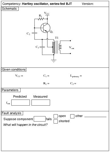
I have had success with the following values:
- �
- VCC = 12 to 24 volts
- �
- C1 = 0.47 mF
- �
- C2 = 0.47 mF
- �
- T1 = 1000:8 W audio matching transformer (used as center-tap inductor)
- �
- R1 = 1.5 MW
- �
- Q1 = part number 2N3403
Capacitors C1 and C2 need not be equal value, since they serve entirely different purposes: C1 is the tank circuit capacitance, while C2 is merely a coupling capacitor. I just happened to be blessed with an abundance of 0.47 mF capacitors when I prototyped this circuit, so I chose that value for both capacitors!
With these component values, the output waveform I measured was not very sinusoidal, but at least it was oscillating. The harmonic output of a Hartley oscillator is substantially greater than a Colpitts, primary because the two capacitors in the Colpitts design act as decoupling capacitances, shunting high-order harmonic signals to ground.
Of course, in order to predict the frequency of oscillation in this Hartley oscillator circuit, you must know the inductance of the audio transformer's primary winding!
You might want to quiz your students on the purpose of resistor R1, since it usually only has to be present at power-up to initiate oscillation!
An extension of this exercise is to incorporate troubleshooting questions. Whether using this exercise as a performance assessment or simply as a concept-building lab, you might want to follow up your students' results by asking them to predict the consequences of certain circuit faults.
Question 58:
|
|
Notes:
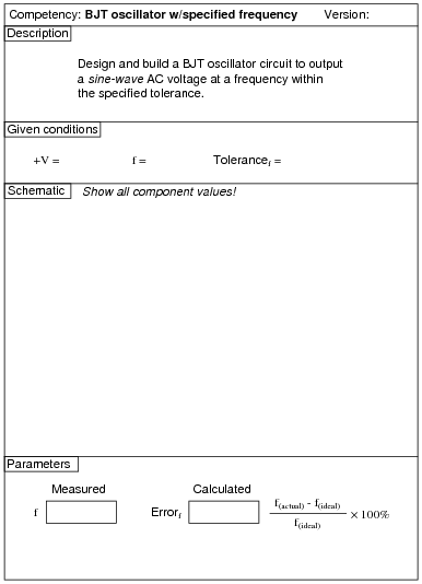
Students are free to choose any oscillator design that meets the criteria: sinusoidal output at a specified frequency.
An extension of this exercise is to incorporate troubleshooting questions. Whether using this exercise as a performance assessment or simply as a concept-building lab, you might want to follow up your students' results by asking them to predict the consequences of certain circuit faults.
Question 59:
|
|
Notes:
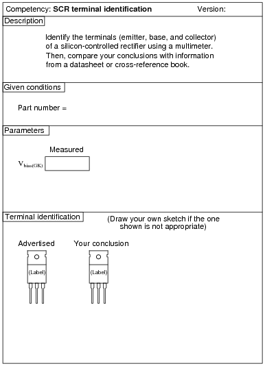
Identification of SCR terminals is a very important skill for technicians to have. Most modern multimeters have a diode check feature which may be used to positively identify PN junction polarities, and this is what I recommend students use for identifying SCR terminals.
This exercise may be made even more interesting if students must differentiate between SCR's with sensitive gates versus SCR's without sensitive gates!
To make this a really good performance assessment, you might want to take several SCR's and scratch the identifying labels off, so students cannot refer to memory for pin identification. Label these thyristors with your own numbers ("1", "2", etc.) so you will know which is which, but not the students!
Question 60:
|
|
Notes:
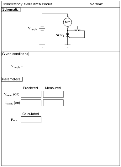
I have had good success using 12 volts DC for the supply voltage, an MCR8SN silicon-controlled rectifier, and a small brushless DC fan motor (80 mA running current) as the load. The MCR8SN is a ßensitive gate" SCR, which makes it easy to demonstrate static triggering (just touch the gate terminal with your finger to start the motor!). Some SCR's may be difficult to keep latched with low-current loads, so be sure to prototype your SCR/load combination before assigning part numbers to your students!
An extension of this exercise is to incorporate troubleshooting questions. Whether using this exercise as a performance assessment or simply as a concept-building lab, you might want to follow up your students' results by asking them to predict the consequences of certain circuit faults.
Question 61:
|
|
Notes:
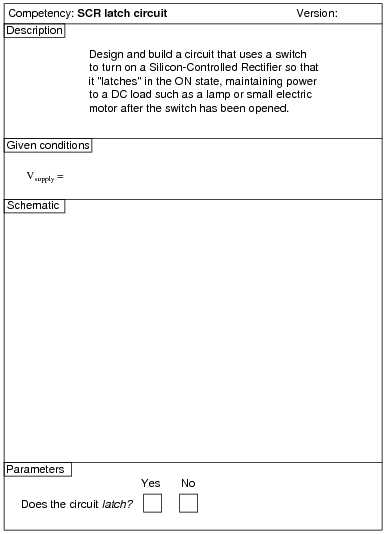
An extension of this exercise is to incorporate troubleshooting questions. Whether using this exercise as a performance assessment or simply as a concept-building lab, you might want to follow up your students' results by asking them to predict the consequences of certain circuit faults.
Question 62:
| (Template) |
|
|
Notes:
Any relevant notes for the assessment activity go here.