Bipolar junction transistors as switches
Question 1:
Solid-state switching circuits usually keep their constituent transistors in one of two modes: cutoff or saturation. Explain what each of these terms means.
Follow-up question: is there such a thing as a state where a transistor operates somewhere between cutoff (fully off) and saturation (fully on)? Would this state be useful in a switching circuit?
Notes:
In all fairness, not all transistor switching circuits operate between these two extreme states. Some types of switching circuits fall shy of true saturation in the ön" state, which allows transistors to switch back to the cutoff mode faster than if they had to switch back from a state of full saturation. ECL (Emitter-Coupled Logic) digital circuits are an example of non-saturating switch circuit technology.
Question 2:
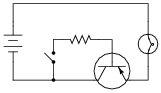
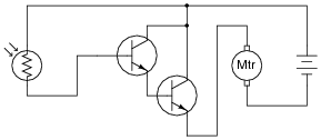
Explain the function of this light-switching circuit, tracing the directions of all currents when the switch closes:
|
|
Question 3:
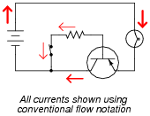
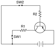
Trace the directions of all currents in this circuit, and determine which current is larger: the current through resistor R1 or the current through resistor R2, assuming equal resistor values.
|
|
If switch SW2 were opened (and switch SW1 remained closed), what would happen to the currents through R1 and R2?
If switch SW1 were opened (and switch SW2 remained closed), what would happen to the currents through R1 and R2?
If SW2 opens while SW1 remains closed, both currents will cease. If SW1 opens while SW2 remains closed, there will be no current through R1, but the current through R2 will actually increase.
Follow-up question: what does this indicate about the nature of the two currents? Which current exerts control over the other through the transistor?
Notes:
The most important principle in this question is that of dependency: one of the transistor's currents needs the other in order to exist, but not visa-versa. I like to emphasize this relationship with the words controlling and controlled.
Question 4:
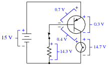
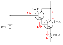
Calculate all component voltage drops in this circuit, assuming a supply voltage of 15 volts, an emitter-base forward voltage drop of 0.7 volts, and a (saturated) emitter-collector voltage drop of 0.3 volts:
|
|
|
|
Notes:
An interesting point that some students may bring up is the 0.4 volt drop across the base-collector junction. Attentive students will note that this junction is supposed to be reverse-biased, but Kirchhoff's Voltage Law clearly specifies the polarity of that 0.4 volt drop, and it is in the direction one would expect for forward biasing of that junction. An examination of the energy diagram for a conducting bipolar junction transistor is really necessary to explain why that junction is considered to be reverse-biased.
Question 5:
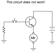
A student attempts to build a circuit that will turn a DC motor on and off with a very delicate (low current rating) pushbutton switch. Unfortunately, there is something wrong with the circuit, because the motor does not turn on no matter what is done with the switch:
|
|
Correct the error(s) in this circuit, showing how it must be set up so that the transistor functions as intended.
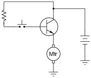
|
|
Notes:
It is very important for your students to learn how the base current controls the collector current in a BJT, and how to use this knowledge to properly set up switching circuits. This is not difficult to learn, but it takes time and practice for many students to master. Be sure to spend adequate time discussing this concept (and circuit design techniques) so they all understand.
Question 6:
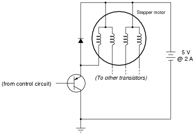
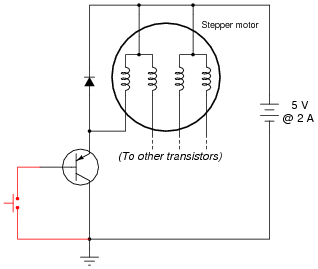
A stepper motor is a special type of electric motor typically used for digital positioning systems. The motor shaft rotates by alternately energizing its coils in a specific sequence. These electromagnet coils draw a fair amount of DC current (several amperes is not uncommon for heavy-duty stepper motors), and as such are usually triggered by power transistors:
|
|
The control circuit that usually sends pulse signals to the base of the power transistors is not shown in this diagram, for simplicity. Your task is to draw a pushbutton switch in this schematic diagram showing how the first motor coil could be manually energized and de-energized. Be sure to note the directions of currents through the transistor, so that your switch is installed correctly!
Also, explain the purpose of the diode connected in parallel with the motor coil. Actually, there will be one of these diodes for each of the motor coils, but the other three are not shown for the sake of simplicity.
|
|
The diode prevents damage to the transistor resulting from inductive "kickback" each time the motor coil is de-energized.
Notes:
It is very important for your students to learn how the base current controls the collector current in a BJT, and how to use this knowledge to properly set up switching circuits. This is not difficult to learn, but it takes time and practice for many students to master. Be sure to spend adequate time discussing this concept (and circuit design techniques) so they all understand.
Question 7:
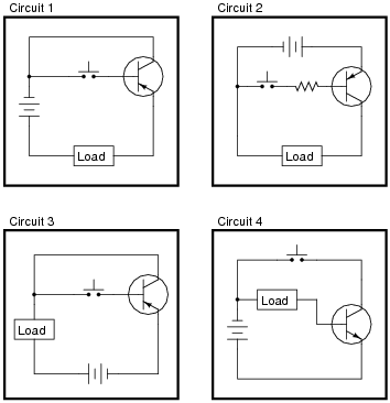
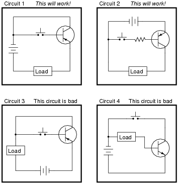
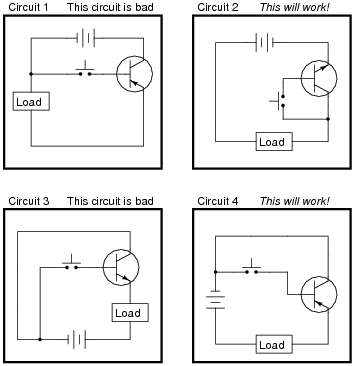
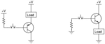
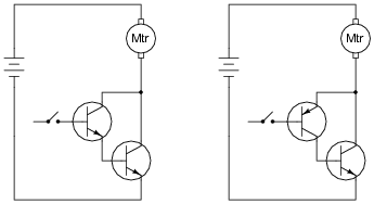
Some of the following transistor switch circuits are properly configured, and some are not. Identify which of these circuits will function properly (i.e. turn on the load when the switch closes) and which of these circuits are mis-wired:
|
|
|
|
Notes:
This is a very important concept for students to learn if they are to do any switch circuit design - a task not limited to engineers. Technicians often must piece together simple transistor switching circuits to accomplish specific tasks on the job, so it is important for them to be able to design switching circuits that will work.
Have your students describe to the class how they were able to determine the status of each circuit, so that everyone may learn new ways of looking at this type of problem. Also have them describe what would have to be changed in the "bad" circuits to make them functional.
Question 8:
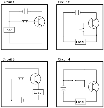
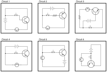
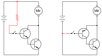
Some of the following transistor switch circuits are properly configured, and some are not. Identify which of these circuits will function properly (i.e. turn on the load when the switch closes) and which of these circuits are mis-wired:
|
|
|
|
Notes:
This is a very important concept for students to learn if they are to do any switch circuit design - a task not limited to engineers. Technicians often must piece together simple transistor switching circuits to accomplish specific tasks on the job, so it is important for them to be able to design switching circuits that will work.
Have your students describe to the class how they were able to determine the status of each circuit, so that everyone may learn new ways of looking at this type of problem. Also have them describe what would have to be changed in the "bad" circuits to make them functional.
Question 9:
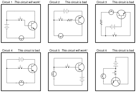
Some of the following transistor switch circuits are properly configured, and some are not. Identify which of these circuits will function properly (i.e. turn on the load when the switch closes) and which of these circuits are mis-wired:
|
|
|
|
Follow-up question: circuit #3 is different from the other "bad" circuits. While the other bad circuits' lamps do not energize at all, the lamp in circuit #3 energizes weakly when the pushbutton switch is open (not actuated). Explain why.
Notes:
This is a very important concept for students to learn if they are to do any switch circuit design - a task not limited to engineers. Technicians often must piece together simple transistor switching circuits to accomplish specific tasks on the job, so it is important for them to be able to design switching circuits that will work.
Have your students describe to the class how they were able to determine the status of each circuit, so that everyone may learn new ways of looking at this type of problem. Also have them describe what would have to be changed in the "bad" circuits to make them functional.
Question 10:
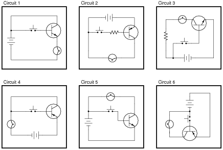
In each of the following circuits, the light bulb will energize when the pushbutton switch is actuated. Assume that the supply voltage in each case is somewhere between 5 and 30 volts DC (with lamps and resistors appropriately sized):
|
|
However, not all of these circuits are properly designed. Some of them will function perfectly, but others will function only once or twice before their transistors fail. Identify the faulty circuits, and explain why they are flawed.
Hint: draw the respective paths of switch and lamp current for each circuit!
Notes:
This is a very important concept for students to learn if they are to do any switch circuit design - a task not limited to engineers. Technicians often must piece together simple transistor switching circuits to accomplish specific tasks on the job, so it is important for them to be able to design switching circuits that will be reliable. A common mistake is to design a circuit so that the transistor receives full supply voltage across the emitter-base junction when ön," as three of the circuits in this question do. The result is sure destruction of the transistor if the supply voltage is substantial.
Circuit #3 is a tricky one! The presence of a resistor might fool some students into thinking base current is limited (as is the case with circuit #2).
Question 11:
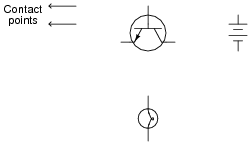
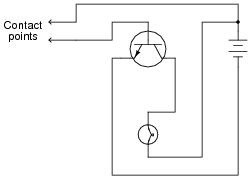
Draw the necessary wire connections so that bridging the two contact points with your finger (creating a high-resistance connection between those points) will turn the light bulb on:
|
|
|
|
Notes:
Once students learn to identify the two current paths (base versus collector), especially the proper directions of current for each, the interconnections become much easier to determine.
Some students may place the light bulb on the emitter terminal of the transistor, in a common-collector configuration. This is not recommended, since it places the light bulb in series with the controlling (base) current path, and this will have the effect of impeding base current, and therefore the controlled (light bulb) current. Given the very high electrical resistance of human skin, this circuit needs all the gain we can possibly muster!
This circuit works well if an LED is substituted for the incandescent lamp.
Question 12:
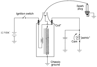
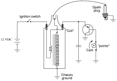
The ignition system of a gasoline-powered internal combustion automobile engine is an example of a transformer operated on DC by means of an oscillating switch contact, commonly referred to as the contact "points":
|
|
The cam-actuated "point" contacts open every time a spark is needed to ignite the air-fuel mixture in one of the engine's cylinders. Naturally, these contacts suffer a substantial amount of wear over time due to the amount of current they must make and break, and the frequency of their cycling.
This device was seen by automotive engineers as a prime candidate for replacement with solid-state technology (i.e., a transistor). If a transistor could take the place of mechanical "point" contacts for making and breaking the ignition coil's current, it should result in increased service life.
Insert a transistor into the following circuit in such a way that it controls the ignition coil's current, with the "point" contacts merely controlling the transistor's state (turning it on and off):
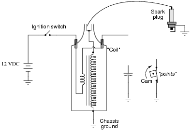
|
|
|
|
Follow-up question: assuming the primary winding of the "coil" has an inductance of 9 mH an a wire resistance of 0.4 W, determine the amount of time necessary to build to full current once the transistor or points have turned on (after 5 time constants' worth of time).
Notes:
Ask your students, "what is the purpose of the capacitor in this circuit?" Inform them that without it, the points would have "burned up" very quickly, and that the transistor will fail almost immediately!
Some of your students familiar with engine ignition systems will notice that there is no distributor for multiple spark plugs. In other words, this circuit is for a single-cylinder engine! I chose not to draw a distributor in this schematic just to keep things simple.
Question 13:
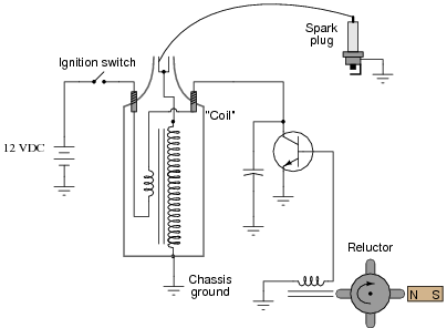
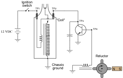
Electronic ignition systems for gasoline-powered engines typically use a device called a reluctor to trigger the transistor to turn on and off. Shown here is a simple reluctor-based electronic ignition system:
|
|
Explain how this circuit functions. Why do you think the triggering device is called a "reluctor"? What advantage(s) does this circuit have over a mechanical "point" operated ignition system?
Notes:
Discuss the advantages of a reluctor-triggered ignition system with your students. As far as I am aware, the system possesses no disadvantages when compared against mechanical point-driven systems.
An interesting side note: one method of testing a reluctor-driven ignition system at high frequencies was to hold the tip of a soldering gun (not a soldering iron!) next to the pickup coil and pull the trigger. The strong magnetic field produced by the gun's high current (60 Hz AC) would trigger the ignition system to deliver 60 sparks per second.
Some of your students familiar with engine ignition systems will notice that there is no distributor for multiple spark plugs. In other words, this circuit is for a single-cylinder engine! I chose not to draw a distributor in this schematic just to keep things simple.
Question 14:
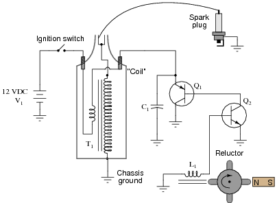
Predict how all component voltages and currents in this circuit will be affected as a result of the following faults. Consider each fault independently (i.e. one at a time, no multiple faults):

|
|
- �
- Transistor Q1 fails open (collector-to-emitter):
- �
- Transistor Q1 fails shorted (collector-to-emitter):
- �
- Reluctor magnet weakens:
- �
- Capacitor C1 fails shorted:
- �
- Capacitor C1 fails open:
- �
- Transformer ("coil") T1 primary winding fails open:
- �
- Transformer ("coil") T1 secondary winding fails open:
For each of these conditions, explain why the resulting effects will occur.
- �
- Transistor Q1 fails open (collector-to-emitter): No current through T1 primary or secondary, no high-voltage pulses across T1 secondary, full 12 volts (constant) across C1, voltage pulses still seen across L1, no spark at spark plug.
- �
- Transistor Q1 fails shorted (collector-to-emitter): Constant current through T1 primary, no high-voltage pulses across T1 secondary, nearly 0 volts across C1, very weak voltage pulses across L1, no spark at spark plug.
- �
- Reluctor magnet weakens: Smaller voltage pulses across L1, smaller current pulses through T1 primary, smaller voltage pulses across T2 secondary, weak or no spark at spark plug.
- �
- Capacitor C1 fails shorted: Constant current through T1 primary, no high-voltage pulses across T1 secondary, nearly 0 volts across C1, normal voltage pulses across L1, no spark at spark plug.
- �
- Capacitor C1 fails open: Excessive voltage pulses seen at Q1 collector (with respect to ground), very rapid failure of Q1.
- �
- Transformer ("coil") T1 primary winding fails open: No current through T1 primary or secondary, no high-voltage pulses across T1 secondary, zero volts (constant) across C1, voltage pulses still seen across L1, no spark at spark plug.
- �
- Transformer ("coil") T1 secondary winding fails open: All voltages and currents fairly normal except for no voltage across T1 secondary and no spark at spark plug, perhaps slightly greater voltage pulses seen at Q1 collector with respect to ground.
Notes:
The purpose of this question is to approach the domain of circuit troubleshooting from a perspective of knowing what the fault is, rather than only knowing what the symptoms are. Although this is not necessarily a realistic perspective, it helps students build the foundational knowledge necessary to diagnose a faulted circuit from empirical data. Questions such as this should be followed (eventually) by other questions asking students to identify likely faults based on measurements.
Question 15:
Predict how all component voltages and currents in this circuit will be affected as a result of the following faults. Consider each fault independently (i.e. one at a time, no multiple faults):
|
|
- �
- Transistor Q2 fails open (collector-to-emitter):
- �
- Transistor Q1 fails shorted (collector-to-emitter):
- �
- Capacitor C1 fails shorted:
- �
- Capacitor C1 fails open:
- �
- Reluctor coil L1 fails open:
For each of these conditions, explain why the resulting effects will occur.
- �
- Transistor Q2 fails open (collector-to-emitter): No current through T1 primary or secondary, no high-voltage pulses across T1 secondary, full 12 volts (constant) across C1, no current through any terminal of Q1, voltage pulses still seen across L1, no spark at spark plug.
- �
- Transistor Q1 fails shorted (collector-to-emitter): Constant current through T1 primary, no high-voltage pulses across T1 secondary, nearly 0 volts across C1, voltage pulses still seen across L1, no spark at spark plug.
- �
- Capacitor C1 fails shorted: Constant current through T1 primary, no high-voltage pulses across T1 secondary, nearly 0 volts across C1, normal voltage pulses across L1, no spark at spark plug.
- �
- Capacitor C1 fails open: Excessive voltage pulses seen at Q1 collector (with respect to ground), very rapid failure of Q1 and possibly Q2.
- �
- Reluctor coil L1 fails open: No current through T1 primary or secondary, no high-voltage pulses across T1 secondary, full 12 volts (constant) across C1, full 12 volts (constant) across Q2 collector-to-emitter, no voltage pulses seen across L1, no spark at spark plug.
Notes:
The purpose of this question is to approach the domain of circuit troubleshooting from a perspective of knowing what the fault is, rather than only knowing what the symptoms are. Although this is not necessarily a realistic perspective, it helps students build the foundational knowledge necessary to diagnose a faulted circuit from empirical data. Questions such as this should be followed (eventually) by other questions asking students to identify likely faults based on measurements.
Question 16:
Choose the right type of bipolar junction transistor for each of these switching applications, drawing the correct transistor symbol inside each circle:
|
|
|
|
Follow-up question: explain why neither of the following transistor circuits will work. When the pushbutton switch is actuated, the load remains de-energized:
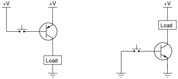
|
|
Notes:
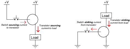
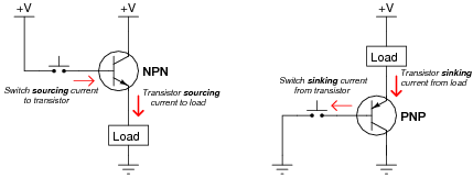
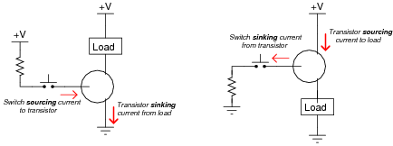
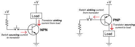
Discuss with your students the meaning of the words ßourcing" and ßinking" in case they are not yet familiar with them. These are very common terms used in electronics (especially digital and power circuitry!), and they make the most sense in the context of conventional flow current notation.
In order for students to properly choose and place each transistor to make the circuits functional, they must understand how BJTs are triggered on (forward-biasing of the base-emitter junction) and also which directions the currents move through BJTs. The two example circuits shown in this question are very realistic.
Question 17:
Choose the right type of bipolar junction transistor for each of these switching applications, drawing the correct transistor symbol inside each circle:
|
|
Also, explain why resistors are necessary in both these circuits for the transistors to function without being damaged.
|
|
Follow-up question: explain why neither of the following transistor circuits will work. When the pushbutton switch is actuated, the load remains de-energized:
|
|
Notes:
Discuss with your students the meaning of the words ßourcing" and ßinking" in case they are not yet familiar with them. These are very common terms used in electronics (especially digital and power circuitry!), and they make the most sense in the context of conventional flow current notation.
In order for students to properly choose and place each transistor to make the circuits functional, they must understand how BJTs are triggered on (forward-biasing of the base-emitter junction) and also which directions the currents move through BJTs. The two example circuits shown in this question are very realistic.
Question 18:
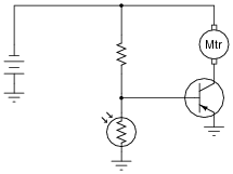
In this circuit, the electric motor is supposed to turn on whenever the cadmium sulfide photocell is darkened:
|
|
Unfortunately, though, the motor refuses to turn on no matter how little light strikes the photocell. In an attempt to troubleshoot the circuit, a technician measures voltage between the collector and emitter terminals of the transistor with the photocell covered by a piece of dark tape, and measures full battery voltage. The technician also measures voltage between the collector and base terminals of the transistor, and measures full battery voltage. At that point, the technician gives up and hands the problem to you.
Based on this information, what do you suspect is faulty in this circuit, and how might you determine the exact location of the fault? Also, identify what you know to be not faulted in the circuit, based on the information given here.
Notes:
It is just as important for your students to be able to identify what is not faulted in a system as it is for them to be able to identify what is faulted. Replacing components that are not faulted is expensive and wasteful!
An essential part of answering this question is what the photocell does when light strikes it. Obviously, it undergoes a change in electrical resistance, but which way? This is something your students will have to determine before they can successfully troubleshoot the system. If they do not understand what the system is supposed to do, they will be helpless in interpreting what it is presently doing.
Question 19:
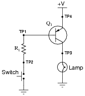
The following circuit used to work fine, but does not work as it should anymore. The lamp does not come on, no matter what is done with the switch:
|
|
The very first thing you do is use your multimeter to check for source voltage, TP4 to ground. Between those points you find 24 volts DC, just as it should be. Next you measure voltage between TP2 and ground with the switch pressed and unpressed. With the switch pressed, there is no voltage between TP2 and ground, but there is voltage (about 23.5 volts) when the switch is unpressed.
From this information, determine at least two possible failures in the circuit which could cause the lamp not to energize, and also account for the voltage measurements taken.
- �
- Lamp burned out
- �
- Transistor failed open at collector terminal
- �
- Bad (open) connection between lamp and transistor
- �
- Bad (open) connection between lamp and ground
Follow-up question: explain why we may say with confidence that there is no problem with the resistor or the switch.
Notes:
Discuss with your students how to reason from the empirical data to a set of possible faults in the circuit, and also how certain areas of the circuit (or individual components) may be safely eliminated from the list of possible faults.
Question 20:
What is the significance of a transistor's beta (b) rating? What, exactly, does this figure mean? Explain how you might set up an experiment to calculate the beta of a given transistor.
Obtain a copy of a datasheet for a small-signal transistor such as the 2N2222 and see what it has to say about that transistor's beta. Note: the beta of a transistor may be represented by the Greek letter (b), or by a completely different symbolism known as a hybrid parameter: hFE
bAC = [(DIC)/(DIB)]
Notes:
The "beta" rating of a transistor is a very important, yet very elusive parameter. Discuss the meaning of this specification with your students, and also their experimental setups for empirically determining beta. Then, compare the results of this discussion with the figures obtained from their datasheets. What do the datasheet figures indicate about the nature of beta as a parameter?
After sharing the datasheet results, re-discuss the experimental setups for measuring beta. Would a single test be sufficient, or would it be advisable to test beta more than once for a given transistor?
Question 21:
Explain what b means for a bipolar junction transistor, in your own words.
Notes:
Many written definitions for b may be found in various textbooks and lexicons. What I am looking for here, as best as possible, is a definition cast in students' own words.
Question 22:
Write the mathematical formula defining b for a bipolar junction transistor:
|
|
Notes:
This definition may be found in any introductory electronics textbook, so you should ask you students to explain something about this formula in order to make it a meaningful discussion question. Suitable explanations to request would be:
- �
- What are some typical values for b?
- �
- Is b always greater than 1 or less than 1? What does this suggest about the two transistor currents in the formula?
- �
- What would the b value be for an ideal transistor?
Question 23:
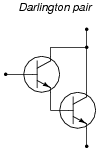
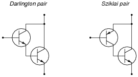
An easy way to increase the effective current gain of a transistor is to "cascade" two of them in a configuration called a Darlington pair:
|
|
Complete this schematic diagram, showing how a Darlington pair could be used to enable a cadmium sulfide (CdS) photocell to turn a motor on and off:

|
|
|
|
Notes:
Ask your students to define "gain" as it applies to a transistor circuit. Ask them to explain why a Darlington pair has a greater current gain than a single transistor, and why that trait is important in a circuit such as this.
Question 24:
Calculate all labeled currents in this Darlington pair circuit (shown in this schematic in conventional flow notation), assuming a typical forward base-emitter junction voltage drop of 0.7 volts for each transistor:
|
|
- �
- I1 = 44.01 mA
- �
- I2 = 113.5 mA
- �
- I3 = 3.785 mA
- �
- I4 = 117.3 mA
Notes:
Have your students come to the front of the class, either as individuals or as groups, and present problem-solving techniques for determining the unknown currents.
Question 25:
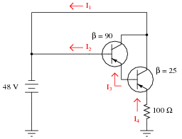
Calculate all labeled currents in this Darlington pair circuit (shown in this schematic in conventional flow notation), assuming a typical forward base-emitter junction voltage drop of 0.7 volts for each transistor:
|
|
- �
- I1 = 465.8 mA
- �
- I2 = 197.0 mA
- �
- I3 = 17.92 mA
- �
- I4 = 466.0 mA
Notes:
Have your students come to the front of the class, either as individuals or as groups, and present problem-solving techniques for determining the unknown currents.
Question 26:
An alternative to the Darlington pair is the Sziklai pair, formed by a complementary pair of bipolar transistors:
|
|
Complete the following circuits, showing how a switch would be connected to each of the transistor pairs to exert control over the electric motor:
|
|
|
|
Follow-up question: why would anyone want to use either a Darlington or Sziklai pair when a single transistor is able to switch current on its own? What advantage do either of these transistor pair configurations give over a single transistor?
Notes:
Sziklai pair circuits are often not discussed in electronics texts until the subject of audio power amplifiers, where the Sziklai pair is offered as an alternative to complementary power transistors in a push-pull circuit (where the final output transistors are both NPN instead of one being NPN and the other PNP). There is nothing wrong, however, with introducing the Sziklai pair configuration in the context of a simple switching circuit as it is done here.
Question 27:
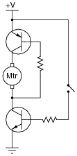
Explain how the one toggle switch is able to switch both transistors on and off simultaneously in this motor control circuit:
|
|
Notes:
This question is really a precursor to analyzing the H-bridge motor drive circuit.
Question 28:
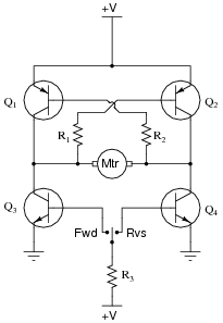
Explain the operation of this "H-bridge" motor control circuit:

|
|
At any given moment, how many transistors are turned on and how many are turned off? Also, explain what would happen to the function of the circuit if resistor R1 failed open.
Challenge question: what type of DC motor is this drive circuit designed for? Shunt-wound, series-wound, compound, or permanent magnet? Explain your answer.
Notes:
The "H-drive" circuit is a very common method of reversing polarity to a DC motor (or other polarity-sensitive load), using only a single-pole switch. Very, very large electric motor "drives" have been based on this same design.
Question 29:
Predict how the motor function in this circuit will be affected as a result of the following faults. Consider each fault independently (i.e. one at a time, no multiple faults):
|
|
- �
- Transistor Q1 fails open (collector-to-emitter):
- �
- Transistor Q2 fails open (collector-to-emitter):
- �
- Transistor Q3 fails open (collector-to-emitter):
- �
- Transistor Q4 fails open (collector-to-emitter):
- �
- Resistor R1 fails open:
- �
- Resistor R2 fails open:
- �
- Resistor R3 fails open:
- �
- Transistor Q3 fails shorted (collector-to-emitter):
- �
- Transistor Q4 fails shorted (collector-to-emitter):
For each of these conditions, explain why the resulting effects will occur.
- �
- Transistor Q1 fails open (collector-to-emitter): Motor fails to turn in "reverse" direction, can still turn in "forward" direction.
- �
- Transistor Q2 fails open (collector-to-emitter): Motor fails to turn in "forward" direction, can still turn in "reverse" direction.
- �
- Transistor Q3 fails open (collector-to-emitter): Motor fails to turn in "forward" direction, can still turn in "reverse" direction.
- �
- Transistor Q4 fails open (collector-to-emitter): Motor fails to turn in "reverse" direction, can still turn in "forward" direction.
- �
- Resistor R1 fails open: Motor fails to turn in "forward" direction, can still turn in "reverse" direction.
- �
- Resistor R2 fails open: Motor fails to turn in "reverse" direction, can still turn in "forward" direction.
- �
- Resistor R3 fails open: Motor cannot turn in either direction.
- �
- Transistor Q3 fails shorted (collector-to-emitter): Motor turns in "forward" direction even when the switch is in the center (off) position.
- �
- Transistor Q4 fails shorted (collector-to-emitter): Motor turns in "reverse" direction even when the switch is in the center (off) position.
Notes:
The purpose of this question is to approach the domain of circuit troubleshooting from a perspective of knowing what the fault is, rather than only knowing what the symptoms are. Although this is not necessarily a realistic perspective, it helps students build the foundational knowledge necessary to diagnose a faulted circuit from empirical data. Questions such as this should be followed (eventually) by other questions asking students to identify likely faults based on measurements.
Question 30:
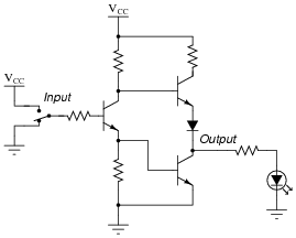
The circuit shown here is part of a digital logic gate circuit:
|
|
Logic circuits operate with their transistors either fully ön" or fully öff," never in-between. Determine what state the LED will be in (either on or off) for both switch positions. You may find it helpful to trace currents and label all voltage drops in this circuit for the two switch states:
|
|
For your voltage drop calculations, assume the following parameters:
- �
- VCC = 5 volts
- �
- VBE (conducting) = 0.7 volts
- �
- VCE (conducting) = 0.3 volts
- �
- Vf (regular diode conducting) = 0.7 volts
- �
- Vf (LED conducting) = 1.6 volts
Notes:
The circuit shown in this question is a partial TTL inverter gate. I opted to simplify the circuit (omitting the ßteering" diodes usually found at the input) for the sake of simplicity, so students could concentrate their attention on the two transistor stages following. Although this circuit may appear intimidating, it is not that difficult to trace currents and calculate voltage drops if one approaches it methodically.
Question 31:
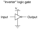
One of the simplest transistor "logic" circuits used in computer circuitry is the so-called inverter gate. Its logic diagram symbol is this:
|
|
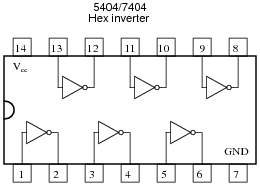
Inverters are often bundled six to a "DIP" (Dual-Inline Package) module, where all gates share the same two power supply connections ("Vcc" and "Ground"), like this:
|
|
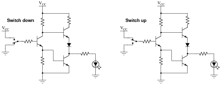
When constructed with bipolar junction transistors, the internal schematic diagram of a single inverter gate looks something like this:

|
|
Being a digital logic circuit, it only ünderstands" two states: on and off. As you can see, a SPDT switch provides signal input into the logic gate, either full supply voltage (VCC) or no voltage at all (Gnd).
Determine the voltage across the load resistance for each of these switch states. Based on your analysis, what is the logical function of an ïnverter" gate?
Notes:
There is much to analyze in this circuit, and this question is not intended to be a full introduction to digital logic. It does, however, provide a preview of things to come, as well as an excellent opportunity to analyze diode and transistor circuitry in the simplest possible way: either fully ön" or fully öff".
One tactic I have found useful as an instructor for analyzing complex circuits in front of a class is to project the image onto a whiteboard using a bright computer projector. Then, you may use dry-erase markers on the whiteboard to "comment" the diagram with voltage and current notations as you proceed to analyze the circuit with your students. Analyzing the circuit for a different logic state is easy: merely erase the "comments" made previously, and the schematic itself is unchanged, ready to be "marked up" again.
Question 32:
There is a problem somewhere in this electronic ignition circuit. The "coil" does not output high voltage as it should when the reluctor spins. A mechanic already changed the coil and replaced it with a new one, but this did not fix the problem.
|
|
You are then asked to look at the circuit to see if you can figure out what is wrong. Using your multimeter, you measure voltage between TP1 and ground (12 volts DC) and also between TP2 and ground (12 volts DC). These voltage readings do not change at all as the reluctor spins.
From this information, identify two possible faults that could account for the problem and all measured values in this circuit, and also identify two circuit elements that could not possibly be to blame (i.e. two things that you know must be functioning properly, no matter what else may be faulted). The circuit elements you identify as either possibly faulted or properly functioning can be wires, traces, and connections as well as components. Be as specific as you can in your answers, identifying both the circuit element and the type of fault.
- �
- Circuit elements that are possibly faulted
- 1.
- 2.
- �
- Circuit elements that must be functioning properly
- 1.
- 2.
- �
- Circuit elements that are possibly faulted
- 1.
- Transistor failed open between collector and emitter
- 2.
- Reluctor coil has failed open
- �
- Circuit elements that must be functioning properly
- 1.
- Battery
- 2.
- Ignition switch
Notes:
Ask your students to identify means by which they could confirm suspected circuit elements, by measuring something other than what has already been measured.
Troubleshooting scenarios are always good for stimulating class discussion. Be sure to spend plenty of time in class with your students developing efficient and logical diagnostic procedures, as this will assist them greatly in their careers.
Question 33:
There is a problem somewhere in this electronic ignition circuit. The "coil" does not output high voltage as it should when the reluctor spins. A mechanic already changed the coil and replaced it with a new one, but this did not fix the problem.

|
|
You are then asked to look at the circuit to see if you can figure out what is wrong. Using your multimeter, you measure voltage between TP1 and ground (12 volts DC) and also between TP2 and ground (0 volts DC). These voltage readings do not change at all as the reluctor spins.
From this information, identify two possible faults that could account for the problem and all measured values in this circuit, and also identify two circuit elements that could not possibly be to blame (i.e. two things that you know must be functioning properly, no matter what else may be faulted). The circuit elements you identify as either possibly faulted or properly functioning can be wires, traces, and connections as well as components. Be as specific as you can in your answers, identifying both the circuit element and the type of fault.
- �
- Circuit elements that are possibly faulted
- 1.
- 2.
- �
- Circuit elements that must be functioning properly
- 1.
- 2.
- �
- Circuit elements that are possibly faulted
- 1.
- Transistor failed shorted between collector and emitter
- 2.
- Capacitor failed shorted
- �
- Circuit elements that must be functioning properly
- 1.
- Battery
- 2.
- Ignition switch
Notes:
Ask your students to identify means by which they could confirm suspected circuit elements, by measuring something other than what has already been measured.
Troubleshooting scenarios are always good for stimulating class discussion. Be sure to spend plenty of time in class with your students developing efficient and logical diagnostic procedures, as this will assist them greatly in their careers.
Question 34:
| Don't just sit there! Build something!! |
Learning to mathematically analyze circuits requires much study and practice. Typically, students practice by working through lots of sample problems and checking their answers against those provided by the textbook or the instructor. While this is good, there is a much better way.
You will learn much more by actually building and analyzing real circuits, letting your test equipment provide the änswers" instead of a book or another person. For successful circuit-building exercises, follow these steps:
- 1.
- Carefully measure and record all component values prior to circuit construction, choosing resistor values high enough to make damage to any active components unlikely.
- 2.
- Draw the schematic diagram for the circuit to be analyzed.
- 3.
- Carefully build this circuit on a breadboard or other convenient medium.
- 4.
- Check the accuracy of the circuit's construction, following each wire to each connection point, and verifying these elements one-by-one on the diagram.
- 5.
- Mathematically analyze the circuit, solving for all voltage and current values.
- 6.
- Carefully measure all voltages and currents, to verify the accuracy of your analysis.
- 7.
- If there are any substantial errors (greater than a few percent), carefully check your circuit's construction against the diagram, then carefully re-calculate the values and re-measure.
When students are first learning about semiconductor devices, and are most likely to damage them by making improper connections in their circuits, I recommend they experiment with large, high-wattage components (1N4001 rectifying diodes, TO-220 or TO-3 case power transistors, etc.), and using dry-cell battery power sources rather than a benchtop power supply. This decreases the likelihood of component damage.
As usual, avoid very high and very low resistor values, to avoid measurement errors caused by meter "loading" (on the high end) and to avoid transistor burnout (on the low end). I recommend resistors between 1 kW and 100 kW.
One way you can save time and reduce the possibility of error is to begin with a very simple circuit and incrementally add components to increase its complexity after each analysis, rather than building a whole new circuit for each practice problem. Another time-saving technique is to re-use the same components in a variety of different circuit configurations. This way, you won't have to measure any component's value more than once.
Notes:
It has been my experience that students require much practice with circuit analysis to become proficient. To this end, instructors usually provide their students with lots of practice problems to work through, and provide answers for students to check their work against. While this approach makes students proficient in circuit theory, it fails to fully educate them.
Students don't just need mathematical practice. They also need real, hands-on practice building circuits and using test equipment. So, I suggest the following alternative approach: students should build their own "practice problems" with real components, and try to mathematically predict the various voltage and current values. This way, the mathematical theory "comes alive," and students gain practical proficiency they wouldn't gain merely by solving equations.
Another reason for following this method of practice is to teach students scientific method: the process of testing a hypothesis (in this case, mathematical predictions) by performing a real experiment. Students will also develop real troubleshooting skills as they occasionally make circuit construction errors.
Spend a few moments of time with your class to review some of the "rules" for building circuits before they begin. Discuss these issues with your students in the same Socratic manner you would normally discuss the worksheet questions, rather than simply telling them what they should and should not do. I never cease to be amazed at how poorly students grasp instructions when presented in a typical lecture (instructor monologue) format!
A note to those instructors who may complain about the "wasted" time required to have students build real circuits instead of just mathematically analyzing theoretical circuits:
What is the purpose of students taking your course?
If your students will be working with real circuits, then they should learn on real circuits whenever possible. If your goal is to educate theoretical physicists, then stick with abstract analysis, by all means! But most of us plan for our students to do something in the real world with the education we give them. The "wasted" time spent building real circuits will pay huge dividends when it comes time for them to apply their knowledge to practical problems.
Furthermore, having students build their own practice problems teaches them how to perform primary research, thus empowering them to continue their electrical/electronics education autonomously.
In most sciences, realistic experiments are much more difficult and expensive to set up than electrical circuits. Nuclear physics, biology, geology, and chemistry professors would just love to be able to have their students apply advanced mathematics to real experiments posing no safety hazard and costing less than a textbook. They can't, but you can. Exploit the convenience inherent to your science, and get those students of yours practicing their math on lots of real circuits!