DC bridge circuits
Question 1:
| Don't just sit there! Build something!! |
Learning to mathematically analyze circuits requires much study and practice. Typically, students practice by working through lots of sample problems and checking their answers against those provided by the textbook or the instructor. While this is good, there is a much better way.
You will learn much more by actually building and analyzing real circuits, letting your test equipment provide the änswers" instead of a book or another person. For successful circuit-building exercises, follow these steps:
- 1.
- Carefully measure and record all component values prior to circuit construction.
- 2.
- Draw the schematic diagram for the circuit to be analyzed.
- 3.
- Carefully build this circuit on a breadboard or other convenient medium.
- 4.
- Check the accuracy of the circuit's construction, following each wire to each connection point, and verifying these elements one-by-one on the diagram.
- 5.
- Mathematically analyze the circuit, solving for all values of voltage, current, etc.
- 6.
- Carefully measure those quantities, to verify the accuracy of your analysis.
- 7.
- If there are any substantial errors (greater than a few percent), carefully check your circuit's construction against the diagram, then carefully re-calculate the values and re-measure.
Avoid very high and very low resistor values, to avoid measurement errors caused by meter "loading". I recommend resistors between 1 kW and 100 kW, unless, of course, the purpose of the circuit is to illustrate the effects of meter loading!
One way you can save time and reduce the possibility of error is to begin with a very simple circuit and incrementally add components to increase its complexity after each analysis, rather than building a whole new circuit for each practice problem. Another time-saving technique is to re-use the same components in a variety of different circuit configurations. This way, you won't have to measure any component's value more than once.
Notes:
It has been my experience that students require much practice with circuit analysis to become proficient. To this end, instructors usually provide their students with lots of practice problems to work through, and provide answers for students to check their work against. While this approach makes students proficient in circuit theory, it fails to fully educate them.
Students don't just need mathematical practice. They also need real, hands-on practice building circuits and using test equipment. So, I suggest the following alternative approach: students should build their own "practice problems" with real components, and try to mathematically predict the various voltage and current values. This way, the mathematical theory "comes alive," and students gain practical proficiency they wouldn't gain merely by solving equations.
Another reason for following this method of practice is to teach students scientific method: the process of testing a hypothesis (in this case, mathematical predictions) by performing a real experiment. Students will also develop real troubleshooting skills as they occasionally make circuit construction errors.
Spend a few moments of time with your class to review some of the "rules" for building circuits before they begin. Discuss these issues with your students in the same Socratic manner you would normally discuss the worksheet questions, rather than simply telling them what they should and should not do. I never cease to be amazed at how poorly students grasp instructions when presented in a typical lecture (instructor monologue) format!
A note to those instructors who may complain about the "wasted" time required to have students build real circuits instead of just mathematically analyzing theoretical circuits:
What is the purpose of students taking your course?
If your students will be working with real circuits, then they should learn on real circuits whenever possible. If your goal is to educate theoretical physicists, then stick with abstract analysis, by all means! But most of us plan for our students to do something in the real world with the education we give them. The "wasted" time spent building real circuits will pay huge dividends when it comes time for them to apply their knowledge to practical problems.
Furthermore, having students build their own practice problems teaches them how to perform primary research, thus empowering them to continue their electrical/electronics education autonomously.
In most sciences, realistic experiments are much more difficult and expensive to set up than electrical circuits. Nuclear physics, biology, geology, and chemistry professors would just love to be able to have their students apply advanced mathematics to real experiments posing no safety hazard and costing less than a textbook. They can't, but you can. Exploit the convenience inherent to your science, and get those students of yours practicing their math on lots of real circuits!
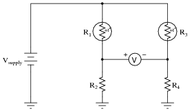
Question 2:
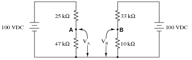
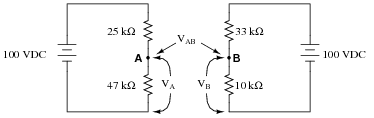
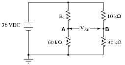
Calculate the output voltages of these two voltage divider circuits (VA and VB):
|
|
Now, calculate the voltage between points A (red lead) and B (black lead) (VAB).
VB = + 23.26 V
VAB = + 42.02 V (point A being positive relative to point B)
Challenge question: what would change if the wire connecting the two voltage divider circuits together were removed?
|
|
Notes:
In this question, I want students to see how the voltage between the two dividers' output terminals is the difference between their individual output voltages. I also want students to see the notation used to denote the voltages (use of subscripts, with an applied reference point of ground). Although voltage is always and forever a quantity between two points, it is appropriate to speak of voltage being ät" a single point in a circuit if there is an implied point of reference (ground).
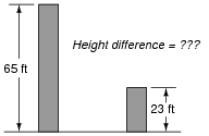
It is possible to solve for VAB without formally appealing to Kirchhoff's Voltage Law. One way I've found helpful to students is to envision the two voltages (VA and VB) as heights of objects, asking the question of "How much height difference is there between the two objects?"
|
|
The height of each object is analogous to the voltage dropped across each of the lower resistors in the voltage divider circuits. Like voltage, height is a quantity measured between two points (the top of the object and ground level). Also like the voltage VAB, the difference in height between the two objects is a measurement taken between two points, and it is also found by subtraction.
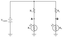
Question 3:
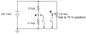
Calculate the output voltages of these two voltage divider circuits (from point A to ground, and from point B to ground:
|
|
Now, calculate the voltage between points A (red lead) and B (black lead).
VB = + 75.0 V
VAB = - 9.72 V
Notes:
In this question, I want students to see how the voltage between the two dividers' output terminals is the difference between their individual output voltages. I also want students to see the notation used to denote the voltages (use of subscripts, with an applied reference point of ground). Although voltage is always and forever a quantity between two points, it is appropriate to speak of voltage being ät" a single point in a circuit if there is an implied point of reference (ground).
Question 4:
How much voltage needs to be dropped across resistor R1 in order to make voltage VAB equal to zero?
|
|
How much resistance must R1 possess in order to drop that amount of voltage?
R1 = 20 kW
Follow-up question: what do you notice about the four resistors' values in this condition where VAB = 0? Pair up these four resistors into two sets of two pairs, and calculate the ratios of those pairs. What do you notice about these ratios?
Notes:
The follow-up question regarding ratios is a good introduction to the fundamental principle of balanced bridge circuits. Having students work through the calculations together is a good way for them to see the principle for themselves.
It is also important to note in this circuit which ratios are not in agreement with each other. You can't just divide these four resistors into any set of two pairs and expect the ratios to equal each other! It is very important for students to see this, as well.
Question 5:
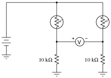
A thermistor is a special resistor that dramatically changes resistance with changes in temperature. Consider the circuit shown below, with two identical thermistors:
|
|
The "+to" label in each one shows that they both have positive a coefficients.
How much voltage would you expect the voltmeter to register when the two thermistors are at the exact same temperature? Which thermistor would have to become hotter in order to cause the voltmeter to read a significant negative voltage?
Notes:
This circuit may be viewed from the perspective of it being two voltage dividers, or from the perspective of being a current divider. Either way, it is a good exercise for you and your students to explore how it functions.
Question 6:
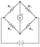
In general terms, describe what must be done to balance this bridge circuit. What, exactly, does the term "balance" mean in this context?
|
|
Also, write an equation containing only the four resistor values (R1, R2, R3, and R4) showing their relationship to one another in a balanced condition.
|
Follow-up question: the bridge-balance equation shown above may also be written in a slightly different form:
|
Show algebraically how the first equation may be manipulated to take the form of the second equation, thus demonstrating these two equations' equivalence.
Notes:
Challenge your students to write a "balance equation" describing how the ratios must relate to each other in order to achieve balance.
Question 7:
Identify the most important qualification for the "null" meter used to balance a bridge circuit. In other words, describe what type of meter we would be looking for if we were to select one for use as a "null" meter. Describe why this particular quality is important.
Notes:
Discuss with your students the definition of ßensitivity" with regard to meter movements, and why null meters have to be sensitive in order for the bridge circuit to be accurately balanced. If your students have studied meter movement design, you may wish to challenge them with a question on exactly how a null meter movement might be constructed (i.e. what would have to be done to maximize its sensitivity?).
Question 8:
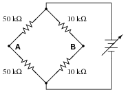
What will happen to the voltage between points A and B if the power supply voltage increases?
|
|
Notes:
This question highlights another important concept of bridge circuits, namely that balance is irrespective of supply voltage.
Question 9:
Explain how this bridge circuit is capable of being "balanced" for any values of R1 and R2:
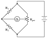
|
|
Notes:
This question showcases one more use of the potentiometer: as a voltage divider used specifically to balance a bridge circuit for any arbitrary values of fixed resistances. If students have difficulty seeing how this is possible, you might want to try representing the pot as a pair of fixed resistors (R3 and R4), the wiper position determining the balance of those two resistance values (Rpot = R1 + R2).
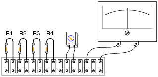
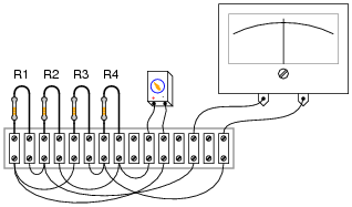
Question 10:
Complete the wire connections necessary to make this a bridge circuit, where [(R1)/(R2)] = [(R3)/(R4)] at balance:
|
|
|
|
Notes:
Challenge your students to connect the resistors in a manner different from the diagram shown in the answer, to make a bridge circuit. A good way to do this is to project an image of the original components (with no interconnections drawn) on a whiteboard with a video projector, then have students use dry-erase markers to draw the connecting wires in place. If any errors are made, they can be very easily erased without erasing any components themselves.
Question 11:
In the early days of electrical metrology, the best way to measure the value of an unknown resistance was to use a bridge circuit. Explain how a four-resistor bridge (a "Wheatstone" bridge) could be used to accurately measure an unknown resistance. What components would this bridge circuit have to be constructed from? Did the power source have to be precision as well? Did the voltmeter in the middle of the bridge have to be accurately calibrated?
Notes:
In the past I've lectured on Wheatstone bridges only to find a fair number of students completely misunderstanding the concept. The fact that a bridge circuit balances when the four arms' resistances are in proportion is the easy part. What these students didn't grasp is how such a bridge might be used to actually measure an unknown resistance, or why it was not possible for them to build a laboratory-usable Wheatstone bridge circuit with the cheap resistors found in their parts kits.
For example, when asked how such a bridge circuit might be used, it was not unusual to hear a student respond that they would make one of the arms of the bridge adjustable, then measure that arm of the bridge with their digital ohmmeter after having achieved balance in order to calculate the unknown resistance by ratio. Though it may seem humorous to an instructor that someone might not realize the sheer existence of a precise ohmmeter would render the bridge circuit obsolete, it nevertheless revealed to me how foreign the concept of a Wheatstone bridge as a resistance measuring circuit is to students working with modern test equipment. Such a technological "generation gap" is not to be underestimated!
In order for students to understand the practicality of a Wheatstone bridge, they need to realize that the only affordable calibration artifacts of the time were standard resistors and standard cells (mercury batteries).
Question 12:
A strain gauge is a device used to measure the strain (compression or expansion) of a solid object by producing a resistance change proportional to the amount of strain. As the gauge is strained, its electrical resistance alters slightly due to changes in wire cross-section and length.
The following strain gauge is shown connected in a "quarter-bridge" circuit (meaning only one-quarter of the bridge actively senses strain, while the other three-quarters of the bridge are fixed in resistance):
|
|
Explain what would happen to the voltage measured across this bridge circuit (VAB) if the strain gauge were to be compressed, assuming that the bridge begins in a balanced condition with no strain on the gauge.
Notes:
Be sure to have your students explain how they arrived at their answers for polarity across the voltmeter terminals. This is the most important part of the question!
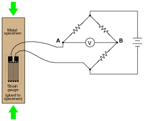
Question 13:
A strain gauge is a device used to measure the strain (compression or expansion) of a solid object by producing a resistance change proportional to the amount of strain:
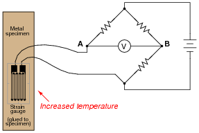
|
|
The bridge circuit is supposed to respond to changes in specimen strain, but explain what will happen to the voltage measured across this bridge circuit (VAB) if the specimen's temperature increases (with no stress applied), assuming that the bridge begins in a balanced condition with no strain on the gauge, at room temperature. Assume a positive a value for the strain gauge conductors.
What does this indicate about the effectiveness of this device as a strain-measuring instrument?
Notes:
Be sure to have your students explain how they arrived at their answers for polarity across the voltmeter terminals.
Ask your students whether or not the fact of the circuit's sensitivity to temperature invalidates its use as a strain-measuring system. Is it impossible to obtain a reliable measurement of strain, if we know temperature also affects the circuit output voltage? How could we compensate for the effects of temperature on the system?
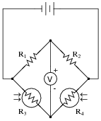
Question 14:
Predict how the operation of this thermistor bridge circuit will be affected as a result of the following faults. Consider each fault independently (i.e. one at a time, no multiple faults):
|
|
- �
- Thermistor R1 fails open:
- �
- Thermistor R3 fails open:
- �
- Solder bridge (short) across thermistor R3:
- �
- Resistor R2 fails open:
- �
- Resistor R4 fails open:
For each of these conditions, explain why the resulting effects will occur.
- �
- Thermistor R1 fails open: Voltmeter "pegs" in the negative direction.
- �
- Thermistor R3 fails open: Voltmeter "pegs" in the positive direction.
- �
- Solder bridge (short) across thermistor R3: Voltmeter "pegs" in the negative direction.
- �
- Resistor R2 fails open: Voltmeter "pegs" in the positive direction.
- �
- Resistor R4 fails open: Voltmeter "pegs" in the negative direction.
Notes:
The purpose of this question is to approach the domain of circuit troubleshooting from a perspective of knowing what the fault is, rather than only knowing what the symptoms are. Although this is not necessarily a realistic perspective, it helps students build the foundational knowledge necessary to diagnose a faulted circuit from empirical data. Questions such as this should be followed (eventually) by other questions asking students to identify likely faults based on measurements.
Question 15:
Predict how the voltage polarity between test points A and B will be affected as a result of the following faults. Consider each fault independently (i.e. one at a time, no multiple faults):
|
|
- �
- Photoresistor R4 fails open:
- �
- Photoresistor R3 fails open:
- �
- Solder bridge (short) across photoresistor R4:
- �
- Resistor R2 fails open:
- �
- Resistor R1 fails open:
For each of these conditions, explain why the resulting effects will occur.
- �
- Photoresistor R4 fails open: Test point B will be positive with respect to test point A (negative).
- �
- Photoresistor R3 fails open: Test point A will be positive with respect to test point B (negative).
- �
- Solder bridge (short) across photoresistor R4: Test point A will be positive with respect to test point B (negative).
- �
- Resistor R2 fails open: Test point A will be positive with respect to test point B (negative).
- �
- Resistor R1 fails open: Test point B will be positive with respect to test point A (negative).
Notes:
The purpose of this question is to approach the domain of circuit troubleshooting from a perspective of knowing what the fault is, rather than only knowing what the symptoms are. Although this is not necessarily a realistic perspective, it helps students build the foundational knowledge necessary to diagnose a faulted circuit from empirical data. Questions such as this should be followed (eventually) by other questions asking students to identify likely faults based on measurements.
Question 16:
This bridge circuit is suppose to generate an output voltage proportional to the difference between light exposure on the two photocells:
|
|
However something has failed in this circuit, because the voltmeter is "pegged" fully negative and will not change with varying light exposures on the two cells. Identify at least two possible failures that could cause the voltmeter to over-range in the negative direction.
- �
- R1 could have failed shorted.
- �
- Photocell R3 could have failed open.
Notes:
Be sure to ask your students to describe failures other than the two mentioned in the answer. And, for all answers given, be sure to ask students how they determined those faults would cause the observed "negative pegging" of the voltmeter. As usual, the method of solution is much more important than the actual answer in this question.
Question 17:
Explain how this strain gauge circuit exploits a property of bridge circuits to provide automatic temperature compensation (so that changes in specimen temperature do not compromise strain measurement accuracy):
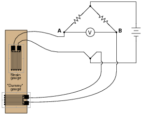
|
|
Follow-up question: suppose the "dummy" strain gauge develops an open failure, so no current may pass through it. Identify the polarity of the voltage drop that will develop across the voltmeter as a result of this fault.
Notes:
Because bridge circuits are inherently differential circuits, it is possible to perform neat "tricks" such as this where the effects of the undesired influence (temperature) become canceled. Incidentally, the principle of cancellation by differential measurement is one that is very common in electronic systems, especially instrumentation systems.
Question 18:
The following bridge circuit uses two strain gauges (one to measure strain, the other to compensate for temperature changes), the amount of strain indicated by the voltmeter in the center of the bridge. Unfortunately, though, it has a problem. Instead of registering a very small voltage as it normally does, the voltmeter shows a large voltage difference, with point A positive and point B negative:
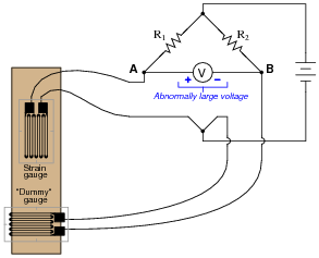
|
|
Something is wrong in the bridge circuit, because this voltage is present even when there is no physical stress on the specimen. Identify which of the following faults could cause the excessive voltage to appear across the voltmeter, and which could not. Consider only one of these faults at a time (no multiple, simultaneous faults):
- �
- Resistor R1 failed open
- �
- Resistor R1 failed shorted
- �
- Resistor R2 failed open
- �
- Resistor R2 failed shorted
- �
- Strain gauge (measurement) failed open
- �
- Strain gauge (measurement) failed shorted
- �
- "Dummy" gauge (temperature compensation) failed open
- �
- "Dummy" gauge (temperature compensation) failed shorted
- �
- Voltage source is dead (no voltage output at all)
- �
- Resistor R1 failed open Not possible
- �
- Resistor R1 failed shorted Possible
- �
- Resistor R2 failed open Possible
- �
- Resistor R2 failed shorted Not possible
- �
- Strain gauge (measurement) failed open Possible
- �
- Strain gauge (measurement) failed shorted Not possible
- �
- "Dummy" gauge (temperature compensation) failed open Not possible
- �
- "Dummy" gauge (temperature compensation) failed shorted Possible
- �
- Voltage source is dead (no voltage output at all) Not possible
Follow-up question: identify possible wire or connection failures in this circuit which could cause the same symptom to manifest.
Notes:
This question helps students build the skill of eliminating unlikely fault possibilities, allowing them to concentrate instead on what is more likely. An important skill in system troubleshooting is the ability to formulate probabilities for various fault scenarios. Without this skill, you will waste a lot of time looking for unlikely faults, thereby wasting time.
For each fault scenario it is important to ask your students why they think it is possible or not possible. It might be that some students get the right answer(s) for the wrong reasons, so it is good to explore the reasoning for each answer.
Question 19:
The following bridge circuit uses two strain gauges (one to measure strain, the other to compensate for temperature changes), the amount of strain indicated by the voltmeter in the center of the bridge. Unfortunately, though, it has a problem. Instead of registering a very small voltage as it normally does, the voltmeter shows a large voltage difference, with point B positive and point A negative:
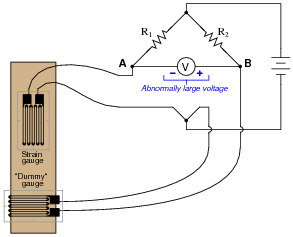
|
|
Something is wrong in the bridge circuit, because this voltage is present even when there is no physical stress on the specimen. Identify which of the following faults could cause the excessive voltage to appear across the voltmeter, and which could not. Consider only one of these faults at a time (no multiple, simultaneous faults):
- �
- Resistor R1 failed open
- �
- Resistor R1 failed shorted
- �
- Resistor R2 failed open
- �
- Resistor R2 failed shorted
- �
- Strain gauge (measurement) failed open
- �
- Strain gauge (measurement) failed shorted
- �
- "Dummy" gauge (temperature compensation) failed open
- �
- "Dummy" gauge (temperature compensation) failed shorted
- �
- Voltage source is dead (no voltage output at all)
- �
- Resistor R1 failed open Possible
- �
- Resistor R1 failed shorted Not possible
- �
- Resistor R2 failed open Not possible
- �
- Resistor R2 failed shorted Possible
- �
- Strain gauge (measurement) failed open Not possible
- �
- Strain gauge (measurement) failed shorted Possible
- �
- "Dummy" gauge (temperature compensation) failed open Possible
- �
- "Dummy" gauge (temperature compensation) failed shorted Not possible
- �
- Voltage source is dead (no voltage output at all) Not possible
Follow-up question: identify possible wire or connection failures in this circuit which could cause the same symptom to manifest.
Notes:
This question helps students build the skill of eliminating unlikely fault possibilities, allowing them to concentrate instead on what is more likely. An important skill in system troubleshooting is the ability to formulate probabilities for various fault scenarios. Without this skill, you will waste a lot of time looking for unlikely faults, thereby wasting time.
For each fault scenario it is important to ask your students why they think it is possible or not possible. It might be that some students get the right answer(s) for the wrong reasons, so it is good to explore the reasoning for each answer.