Characteristic Impedance
Question 1:
|
|
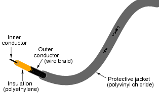
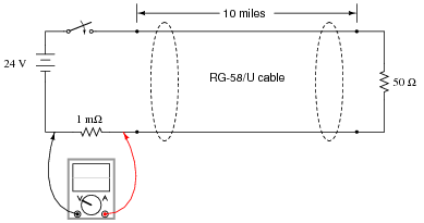
Note the "50 ohm" rating printed on the jacket of the cable. What will an ohmmeter register when connected between the inner conductor and shield of the cable? What will an ohmmeter register when connected between opposite ends of either the inner conductor or the shield, from one end of the cable to the other?
Resistance between ends of inner conductor = nearly 0 ohms
Resistance between ends of shield conductor = nearly 0 ohms
Notes:
It would be a great idea to have some samples of RG-58/U (or other coaxial cable type) available in your laboratory for students to measure themselves. There is nothing like direct, hands-on experimentation to make a point!
Question 2:
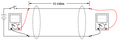
If a battery and switch were connected to one end of a 10-mile long cable, and two oscilloscopes were used to record voltage at either end of the cable, how far apart in time would those two pulses be, assuming a propagation velocity equal to the speed of light (in other words, the cable has a velocity factor equal to 1.0)?

|
|
Notes:
Students should realize by the wording of the question that the voltage signal probably does not arrive at the far end of the cable instantaneously after the switch is closed. Although the speed of light is very, very fast, it is not instant: there will be a measurable time delay.
Question 3:
If a battery and switch were connected to one end of a 10-mile long cable, and two oscilloscopes were used to record voltage at either end of the cable, how far apart in time would those two pulses be, assuming a propagation velocity equal to 69% the speed of light (in other words, the cable has a velocity factor equal to 0.69)?
|
|
Notes:
Students should realize by the wording of the question that the voltage signal probably does not arrive at the far end of the cable instantaneously after the switch is closed. Although 69% of the speed of light is still very, very fast, it is not instant: there will be a measurable time delay.
Question 4:
What does the "50 ohm" rating of an RG-58/U coaxial cable represent? Explain how a simple cable, with no continuity between its two conductors, could possibly be rated in ohms.
Hint: this "50 ohm" rating is commonly referred to as the characteristic impedance of the cable. Another term for this parameter is surge impedance, which I think is more descriptive.
Notes:
This concept will seem very strange to students who are only familiar with resistance in the context of resistors and other simple electrical components, where resistance does not change appreciably over time. In this example, though, the "resistance" of the cable is extremely time-dependent, and the time spans involved are typically very short - so short that measurements made with ohmmeters will not reveal it at all!
Question 5:
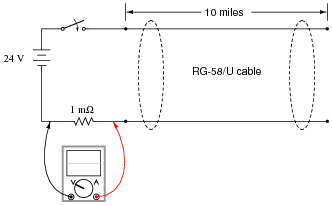
Given the following test circuit, with an oscilloscope used to record current from the battery to the cable (measuring voltage dropped across a shunt resistor), what sort of waveform or pulse would the oscilloscope register after switch closure?
|
|

|
|
The pulse duration should range somewhere between 162.67 microseconds and 170.42 microseconds (based on two different figures I obtained for RG-58/U cable velocity factors).
Notes:
Answering this question requires several steps, and the combining of multiple concepts. It should be apparent from the answer that Ohm's Law (I = E/R) is sufficient for calculating pulse current, but the time delay figure given in the answer may confuse some students. For those students who calculate a time figure that is half as much as the one given in the answer, encourage them to think of why their (incorrect) answer might have been off by 50%. The existence of a 2:1 ratio such as this implies a simple conceptual misunderstanding.
For the RG-58/U cable velocity factor, I obtained two different figures: 0.63 and 0.66, which accounts for the two time delay answers given.
Question 6:
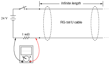
Given the following test circuit, with an oscilloscope used to record current from the battery to the cable (measuring voltage dropped across a shunt resistor), what sort of waveform or pulse would the oscilloscope register after switch closure?
|
|
Notes:
Challenge your students to think of another electrical component (besides an RG-58/U cable of infinite length) that would behave like this, drawing 480 mA of current from a 24 volt source any time the switch is closed. Hint: you don't have to think very hard!
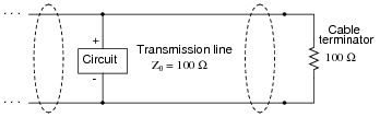
Question 7:
Suppose this 10-mile-long RG-58/U cable were "terminated" by a resistor with a resistance equal to the cable's own characteristic impedance:
|
|
What sort of waveform or pulse would the oscilloscope register after switch closure?
Notes:
Ask your students to compare the behavior of this circuit with that of an unterminated RG-58/U cable. How does this circuit's behavior differ? Why is that?
To phrase the question in a different way, what does the inclusion of a terminating resistor do to the apparent length of the cable? In other words, what length of RG-58/U cable would behave exactly the same as this circuit?
Question 8:
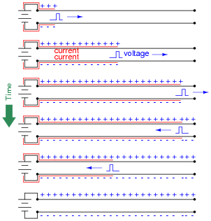
When a pulse propagates down an ünterminated" cable and reaches an open-circuit, what does it do? Does it simply vanish, or does it go some place else?
|
|
After the reflected pulse reaches the source, there will be maximum voltage at the source terminals and zero current in the cable.
Notes:
To help answer this question, it is helpful to ask students how voltage and current relate to each other in an open-circuit condition (maximum voltage, zero current).
Question 9:
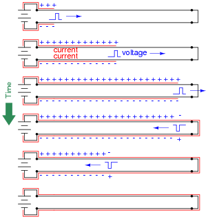
When a pulse propagates down a cable terminated by a short-circuit, what does it do? Does it simply vanish, or does it go some place else?
|
|
After the reflected pulse reaches the source, there will be minimum voltage at the source terminals and maximum current in the cable.
Notes:
To help answer this question, it is helpful to ask students how voltage and current relate to each other in a short-circuit condition (minimum voltage, maximum current).
Question 10:
What will happen if a cable is terminated by a resistor of incorrect value (not equal to the cable's characteristic impedance)?
Notes:
Answering this question is an exercise in qualitative thinking: compare the results of termination with the proper amount of resistance, versus termination with infinite or zero resistance. A terminating resistor of improper value will produce an effect somewhere between these extreme cases.
For instance, compare the cable impedance (as ßeen" by the voltage source after a substantial amount of time) for a properly terminated cable, versus one that is either open-ended or shorted. What would a cable terminated by an improper-value resistor "look" like to the source after the propagation delay time has passed?
Question 11:
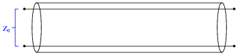
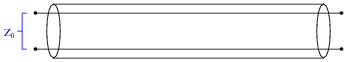
A two-conductor cable of uniform construction will exhibit a uniform characteristic impedance (Z0) due to its intrinsic, distributed inductance and capacitance:
|
|
What would happen to the value of this characteristic impedance if we were to make the cable narrower, so that the conductors were closer together, all other dimensions remaining the same?
|
|
Notes:
Be sure to ask your students to explain why the characteristic impedance will change in the direction it does, based on the known changes to both capacitance and inductance throughout the cable. It should fairly simple for students to explain why capacitance will increase as the two conductors are brought closer together, but it may not be as apparent why the inductance will decrease. A good "Socratic" question to ask is about magnetic field strength, assuming one end of the cable were shorted, and a DC current source connected to the other end. Be sure to remind them to discuss the right-hand corkscrew rule for current and magnetic fields in their answer to this follow-up question!
Question 12:
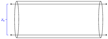
A two-conductor cable of uniform construction will exhibit a uniform characteristic impedance (Z0) due to its intrinsic, distributed inductance and capacitance:

|
|
What would happen to the value of this characteristic impedance if we were to make the cable wider, so that the conductors were further apart, all other dimensions remaining the same?
|
|
Notes:
Be sure to ask your students to explain why the characteristic impedance will change in the direction it does, based on the known changes to both capacitance and inductance throughout the cable. It should fairly simple for students to explain why capacitance will increase as the two conductors are brought closer together, but it may not be as apparent why the inductance will decrease. A good "Socratic" question to ask is about magnetic field strength, assuming one end of the cable were shorted, and a DC current source connected to the other end. Be sure to remind them to discuss the right-hand corkscrew rule for current and magnetic fields in their answer to this follow-up question!
Question 13:
A two-conductor cable of uniform construction will exhibit a uniform characteristic impedance (Z0) due to its intrinsic, distributed inductance and capacitance:

|
|
What would happen to the value of this characteristic impedance if we were to shorten the cable's length, all other dimensions remaining the same?

|
|
Follow-up question: what electrical characteristics would change for this shortened cable?
Notes:
This is sort of a "trick" question, designed to make students think about characteristic impedance, and to test their real comprehension of it. If a student properly understands the physics resulting in characteristic impedance, they will realize length has nothing whatsoever to do with it. Although the cable's total capacitance will change as a result of shortening the cable's length, and the cable's total inductance will likewise decrease for the same reason, these electrical changes should not present a conceptual difficulty to students unless they are modeling the cable in terms of one lumped capacitance and one (or two) lumped inductance(s). If they are thinking in these terms, they have not yet fully grasped the reason why characteristic impedance exists at all.
Question 14:
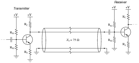
Suppose we were designing a pair of BJT amplifier circuits to connect to either end of a long two-conductor cable:
|
|
How would we choose the component values in each transistor amplifier circuit to naturally terminate both ends of the 75 W cable?
Notes:
This question is really a review of Thévenin's theorem as it applies to common-emitter, divider-biased BJT amplifier circuits.
In case anyone asks, the "zig-zags" in the four lines for the cable represent an unspecified distance between those points. In other words, the cable is longer than what may be proportionately represented on the schematic diagram.
Question 15:
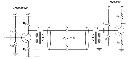
Suppose we were designing a pair of BJT amplifier circuits to connect to either end of a long two-conductor cable, each end coupled to its respective amplifier through a transformer:
|
|
How would we choose the component values in each transistor amplifier circuit to naturally terminate both ends of the 75 W cable?
Notes:
This question is really a review of Thévenin's theorem as it applies to common-emitter, divider-biased BJT amplifier circuits, and also impedance transformation as it applies to step-up and step-down transformers.
In case anyone asks, the "zig-zags" in the four lines for the cable represent an unspecified distance between those points. In other words, the cable is longer than what may be proportionately represented on the schematic diagram.
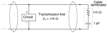
Question 16:
Some communications networks use cables to not only provide a path for data transmission, but also DC power to energize the circuits connected to the cable.
|
|
However, if we were to terminate the cable as shown, the termination resistor would dissipate a substantial amount of power. This is wasted energy, and would unnecessarily burden the power supply providing DC power to the network cable.
How can we eliminate the problem of power dissipated by the termination resistor in a DC power/signal cable and yet still maintain proper termination to avoid reflected signals?
|
|
Notes:
Understanding this answer requires that students recall the filtering behavior of a series capacitor in an AC circuit.
Question 17:
Find a length of coaxial cable and bring it with you to class for discussion. Identify as much information as you can about your piece of cable prior to discussion:
- �
- Characteristic impedance
- �
- Insulation service (cable tray, conduit, direct burial, etc.)
- �
- Type (RG-58, RG-6, etc.)
Notes:
The purpose of this question is to get students to kinesthetically interact with the subject matter. It may seem silly to have students engage in a ßhow and tell" exercise, but I have found that activities such as this greatly help some students. For those learners who are kinesthetic in nature, it is a great help to actually touch real components while they're learning about their function. Of course, this question also provides an excellent opportunity for them to practice interpreting component markings, use a multimeter, access datasheets, etc.