Electrical connections
Question 1:
What, exactly, is necessary to establish electrical continuity between two wires? If I want to have an electric current flow out of one wire and into another, what must be done with those two wires to make that flow path complete?
Conversely, what things might prevent continuity from being established between two wires when they are supposed to electrically connect with one another?
Notes:
It might be helpful to show students what real pieces of wire look like, in order for them to better understand the nature of the problem. Most electrical wire is insulated in one form or another, and this insulation must not be removed (or ßtripped") in order to establish bare metal-to-metal contact.
Question 2:
What type of electrical test would be the most direct means of checking the integrity of an electrical connection between two conductors? Explain your answer.
Notes:
Discuss with your students the ideal resistance of an electrical connection, regardless of type (soldered, terminal strip, wire wrap, wire nut, crimp connector, etc.), and under what conditions you would test the resistance of an electrical connection.
Question 3:
What is the difference between a plug and a jack? What are these two devices used for? Draw the schematic diagram symbols for single-conductor plugs and jacks.

|
|
Notes:
Be sure to inform your students that poor electrical connections, often with regard to plug-and-jack assemblies, are a very common source of failure in electrical and electronic systems.
Question 4:
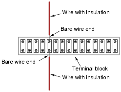
What is a terminal block, or terminal strip? How are these devices used to make electrical connections between different conductors?
|
|
Sometimes, terminal blocks also go by the name of "barrier strips."
Notes:
Be sure to have a variety of terminal blocks available for your students to see and touch during discussion time. Terminal blocks are widely used in industrial applications, for making permanent and semi-permanent connections.
Question 5:
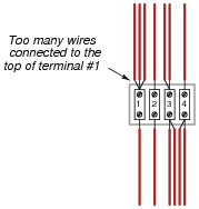
What is generally considered to be the maximum number of individual wires that may be attached to a single terminal on a terminal block?
|
|
Notes:
I'm not sure if there is a specific code or regulation governing the number of terminals connected to a terminal block, but the "no more than two wires per lug" rule makes good sense. That is, of course, unless two conductors stuffed in the same hole would exceed the maximum cross-sectional area limit of the block, then "no more than one wire" is the rule.
I have had the misfortune of seeing egregious violations of both rules in my work experience!
Question 6:
Wire nuts are special electrical connection devices commonly used in residential power wiring. Describe what a "wire nut" is and how they are used to make connections between wires.
Notes:
It would be good to have several sizes of wire nuts available in the classroom for your students to see and touch during discussion.
Question 7:
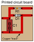
How are connections made between the various wire ends of components inserted into printed circuit boards ("PCBs")?
|
|
Notes:
Be sure to have a variety of printed circuit boards available for your students to see and touch during discussion time. PCBs are widely used in all varieties of electronic applications, and are well suited for mass production manufacturing techniques.
Question 8:
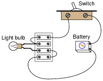
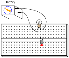
Suppose this circuit has a problem: the light bulb does not light up when the switch is turned ÖN". You suspect that a "bad" connection may exist in the circuit which is preventing current. How would you test the integrity of each connection using a voltmeter only?
|
|
Notes:
It may be more difficult that it first appears to test for voltage across any single connection, if the wires are covered with insulation! Ask your students this question: if you test for voltage between two screws on a terminal strip, how many electrical connections are you actually measuring voltage across?
Question 9:
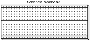
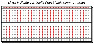
Map the interconnections between holes in a typical solderless breadboard, also commonly known as a proto-board:
|
|
|
|
Notes:
"Mapping" the holes on a solderless breadboard is a fun exercise to do in class with ohmmeters (or any other form of continuity indicator).
Question 10:
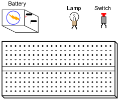
Show how to build a simple circuit consisting of a battery, a lamp, and a switch, mounting the lamp and switch on a solderless breadboard (also known as a proto-board):
|
|
|
|
Notes:
Solderless breadboards are extremely useful tools for prototyping circuits in a classroom/lab environment. Familiarity with their use is a virtual necessity for any modern electronics curriculum. That being said, it is important not to over-emphasize breadboards, though. I have seen some electronics courses where breadboards are the only form of circuit construction students ever use! This does not prepare them for challenges of the job, where breadboards are (rightfully) used only for prototyping.
In summary, use breadboards in your students' labwork, but not all the time, or even most of the time!
Question 11:
What is soldering? What is solder?
"Solder" is a special alloy of metals designed to melt at a low temperature, to make permanent electrical connections.
Notes:
It should be noted that not all forms of soldering are "low temperature." Silver soldering, for example, takes place at much greater temperatures than regular electrical soldering. However, all soldering is a form of welding.
Question 12:
An alternative to soldering components into printed circuit boards is to use a technique called wire wrap. Describe what "wire wrap" is and what applications it might be suitable for.
Notes:
Though wire-wrapping is not as prevalent now as it was a few decades ago, it still has merit for certain applications, notably prototyping. If possible, have some wire-wrapped circuit boards available to show your students during discussion time.
Question 13:
Solderless breadboards provide convenient means for electronics hobbyists, students, technicians, and engineers to build circuits in a non-permanent form. The following illustration shows a three-resistor series circuit built on a breadboard:
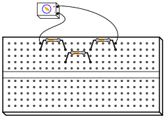
|
|
The interconnections between the metal spring clips within the holes of the breadboard allow continuity between adjacent leads of the resistors, without the resistor leads having to be jammed into the same hole.
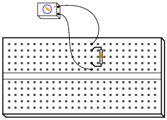
However, new students often get themselves into trouble when first learning how to use solderless breadboards. One common mistake is shown here, where a student has attempted to create a simple single-resistor circuit:
|
|
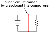
What the student has actually created here is a short circuit. Re-draw this circuit in schematic form, and explain why this circuit is faulty.
|
|
Follow-up question #1: explain what might happen if a large battery or high-current power supply were powering this short circuit.
Follow-up question #2: show how the single-resistor circuit should have been built on the breadboard so as to avoid a short circuit.
Notes:
Situations such as this are very common among new students! Be sure to discuss the significance of ßhort circuits" as well as how to avoid them.