Parallel DC circuits
Question 1:
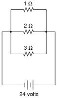
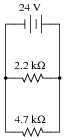
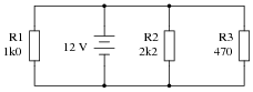
In this circuit, three resistors receive the same amount of voltage (24 volts) from a single source. Calculate the amount of current "drawn" by each resistor, as well as the amount of power dissipated by each resistor:
|
|
I2 W = 12 amps
I3 W = 8 amps
P1 W = 576 watts
P2 W = 288 watts
P3 W = 192 watts
Notes:
The answers to this question may seem paradoxical to students: the lowest value of resistor dissipates the greatest power. Math does not lie, though.
Another purpose of this question is to instill in students' minds the concept of components in a simple parallel circuit all sharing the same amount of voltage.
Challenge your students to recognize any mathematical patterns in the respective currents and power dissipations. What can be said, mathematically, about the current drawn by the 2 W resistor versus the 1 W resistor, for example?
You might want to mention that in electrical parlance, a "heavy" load is one that draws a large amount of current, and thus has a large resistance. This circuit, which shows how the lowest resistance in a parallel circuit consumes the most power, gives practical support to the term "heavy" used to describe loads.
Question 2:
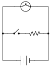
What will happen to the brightness of the light bulb if the switch in this circuit is suddenly closed?
|
|
Notes:
This question illustrates a disparity between the ideal conditions generally assumed for theoretical calculations, and those conditions encountered in real life. Truly, it is the purpose of a voltage source to maintain a constant output voltage regardless of load (current drawn from it), but in real life this is nearly impossible. Most voltage sources exhibit some degree of ßag" in their output over a range of load currents, some worse than others.
In this example, it is impossible to tell how much the voltage source's output will ßag" when the switch is closed, because we have no idea of what the resistor's current draw will be compared to that of the light bulb, or what the voltage source's rated output current is. All we can say is that theoretically there will be no effect from closing the switch, but that in real life there will be some degree of dimming when the switch is closed.
Question 3:
| Don't just sit there! Build something!! |
Learning to mathematically analyze circuits requires much study and practice. Typically, students practice by working through lots of sample problems and checking their answers against those provided by the textbook or the instructor. While this is good, there is a much better way.
You will learn much more by actually building and analyzing real circuits, letting your test equipment provide the änswers" instead of a book or another person. For successful circuit-building exercises, follow these steps:
- 1.
- Carefully measure and record all component values prior to circuit construction.
- 2.
- Draw the schematic diagram for the circuit to be analyzed.
- 3.
- Carefully build this circuit on a breadboard or other convenient medium.
- 4.
- Check the accuracy of the circuit's construction, following each wire to each connection point, and verifying these elements one-by-one on the diagram.
- 5.
- Mathematically analyze the circuit, solving for all values of voltage, current, etc.
- 6.
- Carefully measure those quantities, to verify the accuracy of your analysis.
- 7.
- If there are any substantial errors (greater than a few percent), carefully check your circuit's construction against the diagram, then carefully re-calculate the values and re-measure.
Avoid very high and very low resistor values, to avoid measurement errors caused by meter "loading". I recommend resistors between 1 kW and 100 kW, unless, of course, the purpose of the circuit is to illustrate the effects of meter loading!
One way you can save time and reduce the possibility of error is to begin with a very simple circuit and incrementally add components to increase its complexity after each analysis, rather than building a whole new circuit for each practice problem. Another time-saving technique is to re-use the same components in a variety of different circuit configurations. This way, you won't have to measure any component's value more than once.
Notes:
It has been my experience that students require much practice with circuit analysis to become proficient. To this end, instructors usually provide their students with lots of practice problems to work through, and provide answers for students to check their work against. While this approach makes students proficient in circuit theory, it fails to fully educate them.
Students don't just need mathematical practice. They also need real, hands-on practice building circuits and using test equipment. So, I suggest the following alternative approach: students should build their own "practice problems" with real components, and try to mathematically predict the various voltage and current values. This way, the mathematical theory "comes alive," and students gain practical proficiency they wouldn't gain merely by solving equations.
Another reason for following this method of practice is to teach students scientific method: the process of testing a hypothesis (in this case, mathematical predictions) by performing a real experiment. Students will also develop real troubleshooting skills as they occasionally make circuit construction errors.
Spend a few moments of time with your class to review some of the "rules" for building circuits before they begin. Discuss these issues with your students in the same Socratic manner you would normally discuss the worksheet questions, rather than simply telling them what they should and should not do. I never cease to be amazed at how poorly students grasp instructions when presented in a typical lecture (instructor monologue) format!
A note to those instructors who may complain about the "wasted" time required to have students build real circuits instead of just mathematically analyzing theoretical circuits:
What is the purpose of students taking your course?
If your students will be working with real circuits, then they should learn on real circuits whenever possible. If your goal is to educate theoretical physicists, then stick with abstract analysis, by all means! But most of us plan for our students to do something in the real world with the education we give them. The "wasted" time spent building real circuits will pay huge dividends when it comes time for them to apply their knowledge to practical problems.
Furthermore, having students build their own practice problems teaches them how to perform primary research, thus empowering them to continue their electrical/electronics education autonomously.
In most sciences, realistic experiments are much more difficult and expensive to set up than electrical circuits. Nuclear physics, biology, geology, and chemistry professors would just love to be able to have their students apply advanced mathematics to real experiments posing no safety hazard and costing less than a textbook. They can't, but you can. Exploit the convenience inherent to your science, and get those students of yours practicing their math on lots of real circuits!
Question 4:
The equation for calculating total resistance in a parallel circuit (for any number of parallel resistances) is sometimes written like this:
|
Re-write this equation in such a way that it no longer contains any exponents.
|
Notes:
This question is an exercise in basic algebra, specifically the meaning of negative exponents.
Question 5:
Manipulate this equation to solve for resistor value R1, given the values of R2 and Rparallel:
|
Then, give an example of a practical situation where you might use this new equation.
|
I'll let you figure out a situation where this equation would be useful!
Notes:
This question is really nothing more than an exercise in algebraic manipulation.
Question 6:
The formula for calculating total resistance of three parallel-connected resistors is as follows:
|
Algebraically manipulate this equation to solve for one of the parallel resistances (R1) in terms of the other two parallel resistances (R2 and R3) and the total resistance (R). In other words, write a formula that solves for R1 in terms of all the other variables.
|
Notes:
This question is nothing more than practice algebraically manipulating equations. Ask your students to show you how they solved it, and how the two given answers are equivalent.
Question 7:
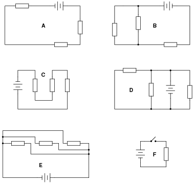
Identify which of these circuits is a parallel circuit (there may be more than one shown!):
|
|
Notes:
The purpose of this question is to get students to identify what distinguishing characteristic uniquely identifies a circuit as being "parallel." Once this has been identified, there are several conclusions which may be deduced (regarding voltage drops, currents, resistances, etc.).
Some students may have difficulty distinguishing that circuit E is a parallel circuit, but it is!
Question 8:
Determine the amount of voltage impressed across each resistor in this circuit:
|
|
Hint: locate all the points in this circuit that are electrically common to one another!
Notes:
The hint suggesting identification of electrically common points is critical to students' understanding of parallel circuits. Once they see that there is no difference (as far as voltage is concerned) between the top of one resistor, the top of the other, or the top of the battery (and likewise for all the bottom connections), it should become clearly evident why voltage must be equal across these three components.
Question 9:
According to Ohm's Law, how much current goes through each of the two resistors in this circuit?
|
|
Draw the paths of all currents in this circuit.
IR(4.7k) = 5.11 mA
|
|
Follow-up question: how much total current does the battery supply to the circuit, given these individual resistor currents?
Notes:
A key element to this question is the plotting of currents. Students need to see how individual resistor currents graphically relate to the total source current in a parallel circuit, because this has direct bearing on the calculation of total current, and also to an understanding of total resistance in parallel circuits.
Question 10:
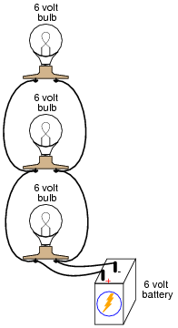
Qualitatively compare the voltage and current for each of the three light bulbs in this circuit (assume the three light bulbs are absolutely identical):
|
|
Notes:
Here, the important principles of voltage and current in a parallel circuit are highlighted. This question serves to further define, in practical ways, what the term "parallel" really means.
An important lesson of this question is the distinction between measurements which are guaranteed to be equal versus measurements which just happen to be equal for a given selection of components.
Question 11:
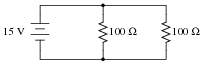
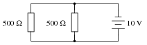
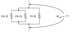
Calculate the total amount of current that the battery must supply to this parallel circuit:
|
|
Now, using Ohm's Law, calculate total resistance (Rtotal) from total (source) voltage Vtotal and total (source) current Itotal.
Rtotal = 250 W
Follow-up question: without appealing to Ohm's Law, explain why the total resistance is one-half as much as either of the individual resistances.
Notes:
While some students seem able to immediately grasp the concept of parallel resistances diminishing in (total) value, it is worthwhile to approach it from an Ohm's Law perspective as well to give other students a more formal rationale for this effect.
Question 12:
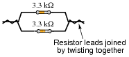
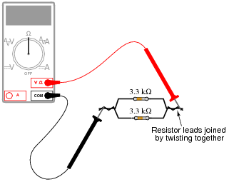
Suppose I connect two resistors in parallel with one another, like this:
|
|
How much electrical resistance would you expect an ohmmeter to indicate if it were connected across the combination of these two parallel-connected resistors?
|
|
Explain the reasoning behind your answer, and try to formulate a generalization for all combinations of parallel resistances.

|
|
Follow-up question: how much resistance would you expect the ohmmeter to register if there were three similarly-sized resistors connected in parallel instead of two? What if there were four resistors?
Notes:
The concept of parallel (total) resistance, in relation to individual resistances, often confuses new students. Be sure to allow plenty of discussion time to work through the conceptual difficulties with them.
Question 13:
There are two well-known formulae for calculating the total resistance of parallel-connected resistances. One of these works only for two resistances, while the other works for any number of parallel resistances. Write these two formulae, and give examples of their use.
|
|
Notes:
Although I typically use the lower formula exclusively in my teaching, the upper formula is often useful for situations where a calculator is not handy, and you must estimate parallel resistance.
Question 14:
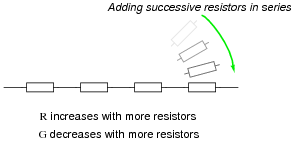
A quantity often useful in electric circuit analysis is conductance, defined as the reciprocal of resistance:
|
In a series circuit, resistance increases and conductance decreases with the addition of more resistors:
|
|
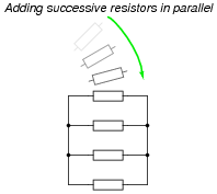
Describe what happens to total resistance and total conductance with the addition of parallel resistors:
|
|
Follow-up question: what is the exact formula that describes total conductance in a network of parallel conductances?
|
Notes:
Once students recognize the mathematical relationship between resistance and conductance (G = 1/R), and they realize that parallel conductances add just like series resistances add, it is but a short exercise in algebra to develop the parallel resistance formula (Rparallel = [1/( [1/(R1)] + [1/(R2)] + �[1/(Rn)] )]).
Question 15:
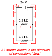
Explain, step by step, how to calculate the amount of current (I) that will go through each resistor in this parallel circuit, and also the voltage (V) dropped by each resistor:
|
|
- IR1 = 12 mA ; VR1 = 12 V
- IR2 = 5.45 mA ; VR2 = 12 V
- IR3 = 25.5 mA ; VR3 = 12 V
Follow-up question: trace the direction of current through all three resistors as well as the power supply (battery symbol). Compare these directions with the polarity of their shared voltage. Explain how the relationship between voltage polarity and current direction relates to each component's identity as either a source or a load.
Notes:
Students often just want to memorize a procedure for determining answers to questions like these. Challenge your students to not only understand the procedure, but to also explain why it must be followed.
Something your students will come to realize in discussion is that there is more than one way to arrive at all the answers! While some of the steps will be common to all calculation strategies, other steps (near the end) leave room for creativity.
Question 16:
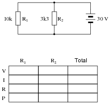
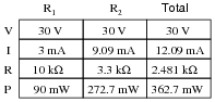
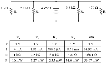
Complete the table of values for this circuit:
|
|
|
|
Notes:
Discuss with your students what a good procedure might be for calculating the unknown values in this problem, and also how they might check their work.
Question 17:
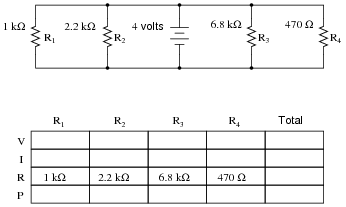
Complete the table of values for this circuit:
|
|
|
|
Notes:
Discuss with your students what a good procedure might be for calculating the unknown values in this problem, and also how they might check their work.
Question 18:
In a parallel circuit, certain general rules may be stated with regard to quantities of voltage, current, resistance, and power. Express these rules, using your own words:
Ïn a parallel circuit, voltage . . ."
Ïn a parallel circuit, current . . ."
Ïn a parallel circuit, resistance . . ."
Ïn a parallel circuit, power . . ."
For each of these rules, explain why it is true.
Ïn a parallel circuit, currents add to equal the total."
Ïn a parallel circuit, resistances diminish to equal the total."
Ïn a parallel circuit, power dissipations add to equal the total."
Notes:
Rules of series and parallel circuits are very important for students to comprehend. However, a trend I have noticed in many students is the habit of memorizing rather than understanding these rules. Students will work hard to memorize the rules without really comprehending why the rules are true, and therefore often fail to recall or apply the rules properly.
An illustrative technique I have found very useful is to have students create their own example circuits in which to test these rules. Simple series and parallel circuits pose little challenge to construct, and therefore serve as excellent learning tools. What could be better, or more authoritative, than learning principles of circuits from real experiments? This is known as primary research, and it constitutes the foundation of scientific inquiry. The greatest problem you will have as an instructor is encouraging your students to take the initiative to build these demonstration circuits on their own, because they are so used to having teachers simply tell them how things work. This is a shame, and it reflects poorly on the state of modern education.
Question 19:
What will happen in this circuit as the switches are sequentially turned on, starting with switch number 1 and ending with switch number 3?
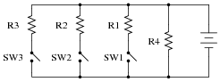
|
|
Describe how the successive closure of these three switches will impact:
- �
- The voltage drop across each resistor
- �
- The current through each resistor
- �
- The total amount of current drawn from the battery
- �
- The total amount of circuit resistance ßeen" by the battery
As the first switch (SW1) is closed, the voltage across resistor R1 will increase to full battery voltage, while the voltages across the remaining resistors will remain unchanged from their previous values. The current through resistor R1 will increase from zero to whatever value is predicted by Ohm's Law (full battery voltage divided by that resistor's resistance), and the current through the remaining resistors will remain unchanged from their previous values. The amount of current drawn from the battery will increase. Overall, the battery ßees" less total resistance than before.
Notes:
One problem I've encountered while teaching the "laws" of parallel circuits is that some students mistakenly think the rule of äll voltages in a parallel circuit being the same" means that the amount of voltage in a parallel circuit is fixed over time and cannot change. The root of this misunderstanding is memorization rather than comprehension: students memorize the rule "all voltages are the same" and think this means the voltages must remain the same before and after any change is made to the circuit. I've actually had students complain to me, saying, "But you told us all voltages are the same in a parallel circuit!", as though it were my job to decree perfect and universal Laws which would require no critical thinking on the part of the student. But I digress . . .
This question challenges students' comprehension of parallel circuit behavior by asking what happens after a change is made to the circuit. The purpose of the switches is to ädd" resistors from the circuit, one at a time, without actually having to insert new components.
Question 20:
The circuit shown here is commonly referred to as a current divider. Calculate the voltage dropped across each resistor, the current drawn by each resistor, and the total amount of electrical resistance ßeen" by the 9-volt battery:
|
|
- �
- Current through the 2 kW resistor =
- �
- Current through the 3 kW resistor =
- �
- Current through the 5 kW resistor =
- �
- Voltage across each resistor =
- �
- Rtotal =
Can you think of any practical applications for a circuit such as this?
- �
- Current through the 2 kW resistor = 4.5 mA
- �
- Current through the 3 kW resistor = 3 mA
- �
- Current through the 5 kW resistor = 1.8 mA
- �
- Voltage across each resistor = 9 volts
- �
- Rtotal = 967.74 W
How much current is drawn from the battery in this circuit? How does this figure relate to the individual resistor currents, and to the total resistance value?
Notes:
Some students may find the diagram hard to follow, and so they will find the task of analysis helped by drawing an equivalent schematic diagram for this circuit, with all terminal points labeled. I recommend you not suggest this solution immediately, but rather challenge your students to think of problem-solving techniques on their own. Surely, someone in the class will have thought of doing this, and the impact of such a suggestion coming from a peer is greater than if it came from you, the instructor.
Be sure to ask your students this question: "Why is this type of circuit commonly called a current divider?"
Question 21:
There is a simple equation that gives the equivalent resistance of two resistances connected in parallel. Write this equation.
Secondly, apply this two-resistance equation to the solution for total resistance in this three-resistor network:
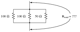
|
|
No, this is not a "trick" question! There is a way to apply a two-resistance equation to solve for three resistances connected in parallel.
In case you are still unsure of how to apply the "two-resistance" parallel equation to this network, I'll give you a hint: this equation gives the equivalent resistance of two parallel-connected resistors. Examine this modified version of the original schematic diagram:
|
|
Notes:
And who said technological work never involves creativity? This question challenges students to apply an equation to a problem that it is not ideally suited for. The basic principle used in the solution of the problem is very practical. It involves the substitution of an equivalent component value in place of multiple components, which is a problem-solving technique widely applied in electrical network analysis, as well as other forms of mathematical analysis.
Question 22:
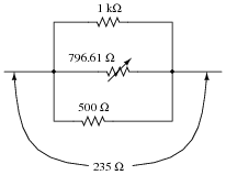
Suppose you needed a resistance equal to precisely 235 W for the construction of a precision electrical meter circuit. The only resistors available to you are two 1 kW resistors, one 500 W resistor, and a rheostat variable between 600 and 1000 ohms. Design a parallel resistor network using any combination of these components that will yield a total resistance of 235 W. If you use the rheostat in your design, specify its resistance setting.
|
|
Notes:
This problem is an exercise in estimation, and algebraic equation manipulation. Estimation will reveal which resistors should be combined together, and algebraic manipulation will give the exact values needed.
Question 23:
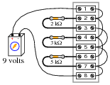
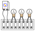
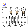
Draw the connecting wires on this terminal strip so that the three light bulbs are wired in parallel with each other and with the battery.
|
|
|
|
Notes:
One of the more difficult visualization tasks for new students of electronics is translating schematic diagrams to physical layouts, and visa-versa. This, sadly, is a skill that I don't see emphasized nearly enough in most basic electronics curricula. It seems the majority of class time is spent mathematically analyzing useless resistor networks, and not enough time is invested building students' spatial relations skills.
While series connections are very easy to visualize on terminal strips, parallel connections are more difficult. Work with your students through this question helping those who lack the innate spatial relations ability to see the solution quickly.
A "trick" I often use to help students build this skill is to have them first draw a nice, clean schematic diagram. Then they over-trace each wire in the diagram as they draw it in the pictorial diagram. In this way, they make sure not to overlook connections in the pictorial diagram.
Question 24:
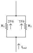
Choose two resistor values such that one resistor passes 25% of the total current, while the other resistor passes 75% of the total current:
|
|
Notes:
This is a fine example of a question with multiple correct answers. No matter how many unique combinations students invent, they may all be verified by a few simple Ohm's Law calculations.