Delta and Wye 3-phase circuits
Question 1:
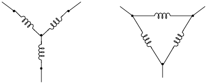
Label where each of the following electrical quantities would be found in both the "Y" and "Delta" three-phase configurations:
- �
- Phase voltage
- �
- Line voltage
- �
- Phase current
- �
- Line current
|
|
In which circuit (Y or Delta) are the phase and line currents equal? In which circuit (Y or Delta) are the phase and line voltages equal? Explain both answers, in terms that anyone with a basic knowledge of electricity could understand.
Where phase and line quantities are unequal, determine which is larger.
|
|
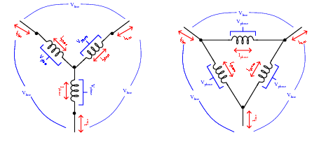
- Y configuration
- �
- Iphase = Iline
- �
- Vphase < Vline
- Delta configuration
- �
- Vphase = Vline
- �
- Iphase < Iline
Follow-up question: how do Kirchhoff's Voltage and Current Laws explain the relationships between unequal quantities in "Y" and "Delta" configurations?
Notes:
Your students will need to know what "phase" and "line" represents in both types of polyphase configurations, especially when using formulae that reference quantities by these labels.
Question 2:
Explain the difference between a balanced polyphase system and an unbalanced polyphase system. What conditions typically cause a polyphase system to become unbalanced?
Notes:
Ask your students which type of three-phase system (balanced or unbalanced) is easier to analyze, and why that is so.
Question 3:
In a balanced Y-connected power system, calculate the phase voltage (Ephase) if the line voltage (Eline) is 480 volts.
Notes:
More important than obtaining the correct answer is for students to explain what they did to get that answer. What general calculation may be applied to balanced, Y-connected systems relating phase and line voltages?
Question 4:
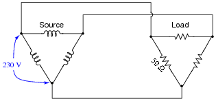
Calculate all voltages, currents, and total power in this balanced Delta-Delta system:
|
|
- Eline =
- Iline =
- Ephase(source) =
- Iphase(source) =
- Ephase(load) =
- Iphase(load) =
- Ptotal =
- Eline = 230 V
- Iline = 7.967 A
- Ephase(source) = 230 V
- Iphase(source) = 4.6 A
- Ephase(load) = 230 V
- Iphase(load) = 4.6 A
- Ptotal = 3.174 kW
Notes:
Be sure to ask your students to describe how they arrived at the answers to this question. There is more than one place to start in determining the solution here, and more than one way to calculate some of the figures. No matter how your students may have approached this question, though, they should all obtain the same answers.
Question 5:
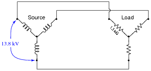
Calculate all voltages, currents, and total power in this balanced Y-Y system:
|
|
- Eline =
- Iline =
- Ephase(source) =
- Iphase(source) =
- Ephase(load) =
- Iphase(load) =
- Ptotal =
- Eline = 13.8 kV
- Iline = 5.312 A
- Ephase(source) = 7.967 kV
- Iphase(source) = 5.312 A
- Ephase(load) = 7.967 kV
- Iphase(load) = 5.312 A
- Ptotal = 126.96 kW
Notes:
Be sure to ask your students to describe how they arrived at the answers to this question. There is more than one place to start in determining the solution here, and more than one way to calculate some of the figures. No matter how your students may have approached this question, though, they should all obtain the same answers.
Question 6:
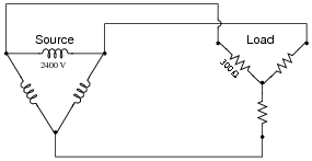
Calculate all voltages, currents, and total power in this balanced Delta-Y system:
|
|
- Eline =
- Iline =
- Ephase(source) =
- Iphase(source) =
- Ephase(load) =
- Iphase(load) =
- Ptotal =
- Eline = 2400 V
- Iline = 4.619 A
- Ephase(source) = 2400 V
- Iphase(source) = 2.667 A
- Ephase(load) = 1385.6 V
- Iphase(load) = 4.619 A
- Ptotal = 19.2 kW
Notes:
Be sure to ask your students to describe how they arrived at the answers to this question. There is more than one place to start in determining the solution here, and more than one way to calculate some of the figures. No matter how your students may have approached this question, though, they should all obtain the same answers.
Question 7:
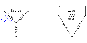
Calculate all voltages, currents, and total power in this balanced Y-Delta system:
|
|
- Eline =
- Iline =
- Ephase(source) =
- Iphase(source) =
- Ephase(load) =
- Iphase(load) =
- Ptotal =
- Eline = 207.8 V
- Iline = 0.621 A
- Ephase(source) = 120 V
- Iphase(source) = 0.621 A
- Ephase(load) = 207.8 V
- Iphase(load) = 0.358 A
- Ptotal = 223.4 W
Notes:
Be sure to ask your students to describe how they arrived at the answers to this question. There is more than one place to start in determining the solution here, and more than one way to calculate some of the figures. No matter how your students may have approached this question, though, they should all obtain the same answers.
Question 8:
What resistor values would we have to choose in a Delta configuration to behave exactly the same as this Y-connected resistor network?

|
|
Notes:
There exist long, complicated equations for converting between Y and Delta resistor networks, but there is a much simpler solution to this problem than that! Challenge your students to solve this problem without resorting to the use of one of those long conversion formulae.
Question 9:
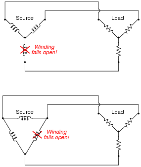
What will happen in each of these systems to the phase voltages of the load, if one of the source phases fails open?
|
|
In the Delta-Y system, none of the phase voltages will be affected by the failure of the source phase winding.
Notes:
Ask your students what these results indicate about the reliability of Y versus Delta source configurations. Also, be sure to ask what does change in the Delta-Y system as a result of the failure. Certainly, something must be different from before, with one winding completely failed open!
Question 10:
A common three-phase source connection scheme is the Delta high-leg or Four-wire Delta, where each phase coil outputs 240 volts:

|
|
Identify the different voltages obtained from this coil configuration, and which connection points each voltage is measured between.
VAN = 120 volts VBN = 208 volts VCN = 120 volts
Notes:
The usefulness of this connection scheme should be clearly evident: three different voltage levels may be accessed for use in powering circuits. Usually, the coils shown are secondary windings of three different transformers, the primary windings connected to a set of three-phase high voltage power lines. In many cases, a heavier-duty transformer is used for coil AC than for coils AB or BC due to the number of 120 volt loads.
Question 11:
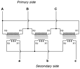
Identify the primary-secondary connection configuration of these three power transformers (i.e. Y-Y, Y-Delta, Delta-Y, etc.):
|
|
Notes:
Three-phase power transformers are somewhat rare compared to combinations of multiple single-phase transformers. Questions such as this are really nothing more than pattern-recognition exercises, but like all skills this does not come naturally to all people, and practice improves it!
Question 12:
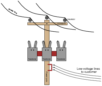
An electrical lineman is connecting three single-phase transformers in a Y(primary)-Y(secondary) configuration, for power service to a business. Draw the connecting wires necessary between the transformer windings, and between the transformer terminals and the lines:
|
|
Note: fuses have been omitted from this illustration, for simplicity.
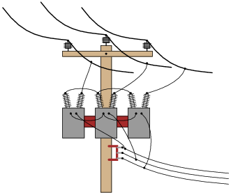
|
|
Of course, this is not the only way these three transformers could be connected in a Y-Y configuration.
Notes:
Being that pole-mounted power distribution transformers are exposed for anyone to look at, they provide an excellent opportunity for students to practice identifying three-phase connections. If there are any such transformer configurations located near your campus, it would be an interesting field exercise to bring students there (or send them there on "field research"!) to identify the connections. Photographs of transformer connections may also be used in the classroom to provide practical examples of this concept.
Question 13:
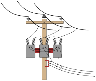
Identify the primary-secondary connection configuration of these pole-mounted power transformers (i.e. Y-Y, Y-Delta, Delta-Y, etc.):
|
|
Notes:
Being that pole-mounted power distribution transformers are exposed for anyone to look at, they provide an excellent opportunity for students to practice identifying three-phase connections. If there are any such transformer configurations located near your campus, it would be an interesting field exercise to bring students there (or send them there on "field research"!) to identify the connections. Photographs of transformer connections may also be used in the classroom to provide practical examples of this concept.
Question 14:
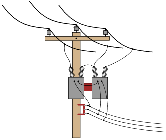
Identify the primary-secondary connection configuration of these pole-mounted power transformers (i.e. Y-Y, Y-Delta, Delta-Y, etc.):
|
|
Notes:
Understanding the open-Delta configuration is made easier if students first understand the robustness of the regular Delta configuration: how it continues to provide true three-phase power with no degradation in line voltage in the event of a winding failure. Discuss the advantages and disadvantages of such a configuration with your students.
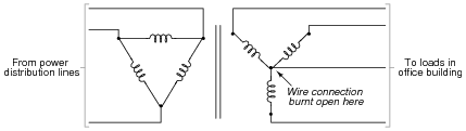
Question 15:
One of the conductors connecting the secondary of a three-phase power distribution transformer to a large office building fails open. Upon inspection, the source of the failure is obvious: the wire overheated at a point of contact with a terminal block, until it physically separated from the terminal.
|
|
What is strange, though, is that the overheated wire is the neutral conductor, not any one of the "line" conductors. Based on this observation, what do you think caused the failure?
After repairing the wire, what would you do to verify the cause of the failure?
Notes:
This scenario is all too common in modern power systems, as non-linear loads such as switching power supplies and electronic power controls become more prevalent. Special instruments exist to measure harmonics in power systems, but a simple DMM (digital multimeter) may be used as well to make crude assessments such as the one described in the Answer.