Digital logic signals
Question 1:
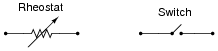
A rheostat (variable resistor) and a switch are both examples of electric components exhibiting different degrees of conductivity:
|
|
Which of these devices would be considered discrete and which would be considered continuous in terms of their electrical conductivity? What do each of these words mean, and how might they apply to variables in electric circuits other than conductivity?
Follow-up question: what is the difference between a continuous voltage versus a discrete voltage?
Notes:
The purpose of this question is to get students thinking in terms of "digital" quantities, which by their very nature are non-continuous. Since most electronics curricula focus on continuous quantities before discrete, it is good to have students reflect on the inherent simplicity of discrete circuitry and components after having studied continuous (analog) circuitry.
Question 2:
Digital logic circuitry makes use of discrete voltage levels: each "logic gate" sub-circuit inputs and outputs voltages that are either considered "high" or "low". Define what both of these terms means in a digital logic circuit powered by 5 volts DC.
"Low" = (nearly) 0 volts between the gate input/output and ground.
Notes:
This is a very simple concept, but worthwhile to cover in its own question just to be sure no students misunderstand when the concept is later applied.
Question 3:
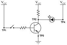
Determine the logic levels (either "high" or "low") at each of the test points in this circuit with the toggle switch in the open position, as well as the status of the transistor and LED:
|
|
- �
- VTP1 = (high or low?)
- �
- VTP2 = (high or low?)
- �
- VTP3 = (high or low?)
- �
- VTP4 = (high or low?)
- �
- Transistor = (on or off?)
- �
- LED = (on or off?)
- �
- VTP1 = high
- �
- VTP2 = high
- �
- VTP3 = low
- �
- VTP4 = high
- �
- Transistor = off
- �
- LED = off
Follow-up question: show how you would calculate reasonable values for the two resistors in this circuit.
Notes:
This question applies the concepts of "high" and "low" voltage signals to a simple transistor circuit, reviewing transistor operation in the process.
Question 4:
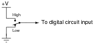
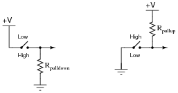
If we need to produce a discrete logic signal ("high" or "low") from a mechanical switch, the most direct way of doing so is to use a single-pole, double-throw switch (SPDT) like this:
|
|
In the "High" position, the switch directly connects the signal line to +V, ensuring a high logic state; in the "Low" position, the switch directly connects the signal line to ground, ensuring a low logic state. What could be simpler?
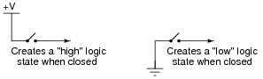
However, often a SPDT switch is not feasible and we must use a SPST (single-pole, single-throw) switch instead:
|
|
A problem often arises with such configurations because in the open position there is neither a connection to +V nor ground. In other words, these two SPST configurations produce the exact same indeterminate logic state ("floating") when their respective switches are open. To remedy this, resistors are often added to such circuits:
|
|
Explain what functions the pulldown and pullup resistors serve, and also why they are referred to by those names.
Follow-up question: to better understand the purpose of these resistors, examine the following circuits without pulldown and pullup resistors to determine what the logic states of the wires will be in both switch positions. Then, add either pulldown or pullup resistors and re-examine the circuits:
Challenge question: how does one calculate the proper resistance (in ohms) for a pulldown or pullup resistor? Will any size work, or is there such a thing as too large or too small?

|
|
Notes:
If students do not understand the purpose of these resistors after reading the question and researching their texts, they should when they see the follow-up question. Discuss this question with your students, for the concept of pulldown and pullup resistors is one that confuses some students.
Question 5:
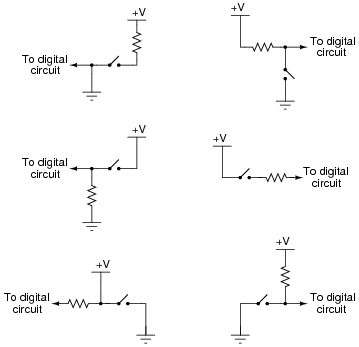
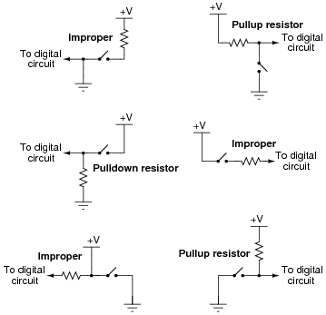
A common mistake made by students new to digital circuits is to misplace the pullup or pulldown resistors in schematic diagrams, and also in the circuits they build. Study the following schematics and determine whether the resistor in each one is a properly-placed pullup or pulldown resistor, or if it is improperly placed:
|
|
|
|
Follow-up question: specifically identify what would be wrong with each of the ïmproper" circuits.
Notes:
This is one concept I have found many students have difficulty grasping, essentially because it involves the determination of a voltage drop between two points (the ärrow" wire and ground). It is a spatial-relations problem, similar to Kirchhoff's Voltage Law problems where students need to figure out how much voltage is between two specified points given voltage drops across several other pairs of points. Spend time with your students discussing these circuits, because several of your students will probably not understand this concept the first, second, or even third time through.
I strongly recommend students take the approach of a "thought experiment" in determining the efficacy of each circuit shown here: analyze the output voltage (logic state) for each of the switch's two positions. This simple approach usually helps clarify what each circuit does and why the ïmproper" circuits do not work.
Question 6:
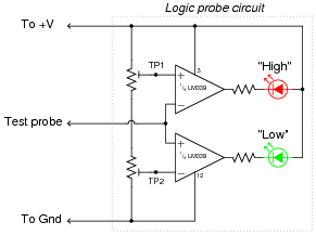
A logic probe is a very useful tool for working with digital logic circuits. It indicates "high" and "low" logic states by means of LED's, giving visual indication only if the voltage levels are appropriate for each state.
Here is a schematic diagram for a logic probe built using comparators. Each comparator has a threshold adjustment potentiometer, so that it may be set to indicate its respective logic state only if the signal voltage is well within the range stated by the logic manufacturer:
|
|
Explain how this circuit functions.
Follow-up question #1: explain how you could use a voltmeter as a logic probe to do troubleshooting in a digital circuit.
Follow-up question #2: write a formula for calculating appropriate current-limiting resistor sizes for the two LEDs in this circuit, given the value of +V and the LED forward voltage and current values.
Notes:
It is important for students to understand that there is a certain range of voltage between a guaranteed "high" state and a guaranteed "low" state that is indeterminate, and that this logic probe circuit is designed to indicate this range of voltage by turning neither LED on.
If time permits, discuss some of the benefits and drawbacks to using a voltmeter as a logic probe (especially a digital voltmeter where the display update time may be relatively long).
Question 7:
Identify whether each of these quantities is continuous or discrete:
- �
- Resistance of a rheostat:
- �
- Resistance of a switch:
- �
- Time represented by an analog clock:
- �
- Time represented by a digital clock:
- �
- Quantity of money in a billfold (bills and coins):
- �
- Number of pebbles held in a hand:
- �
- A person's weight, in pounds or kilograms:
- �
- Voltage output by a comparator:
- �
- Voltage output by an operational amplifier:
- �
- Electrical conductivity of a thyristor:
- �
- Resistance of a rheostat: continuous
- �
- Resistance of a switch: discrete
- �
- Time represented by an analog clock: continuous
- �
- Time represented by a digital clock: discrete
- �
- Quantity of money in a billfold (bills and coins): discrete
- �
- Number of pebbles held in a hand: discrete
- �
- A person's weight, in pounds or kilograms: continuous
- �
- Voltage output by a comparator: discrete
- �
- Voltage output by an operational amplifier: continuous (if negative feedback is applied)
- �
- Electrical conductivity of a thyristor: discrete
Notes:
The purpose of this question is to get students thinking in terms of "digital" quantities, which by their very nature are non-continuous. It is important to note that the concepts of continuous and discrete quantities are not limited to electronics, but are found in a variety of places in every-day life.
It should be noted that some of these determinations are subjective. The voltage output by a comparator may be considered discrete on a large time scale, but there is a measurable transition from "high" voltage to "low" voltage in which the output voltage is somewhere between full saturation limits.
Question 8:
Two computational aids of antiquity are the abacus and the slide rule. Which of these mathematical instruments would be considered änalog" and which would be considered "digital"? Explain your answer.
Notes:
One challenge to answering this question is for (young) students to figure out what a slide rule is!
Question 9:
In digital electronic circuitry, binary bit values of 0 or 1 are represented in the form of voltages: low and high logic states, respectively. Suppose you need to manually ïnput" a logic state to one of the pins of a logic circuit. In the following illustration, the logic circuit (shown as an indistinct, shaded rectangle) is already supplied with DC power (+V and ground), and its output is indicated by an LED. All it requires is an input from you:
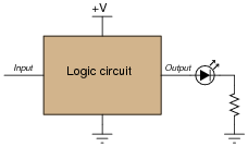
|
|
Complete this schematic diagram by including a switch in the drawing, such that in each of its two positions, a definite "low" or "high" logic state will be sensed by the circuit's input terminal.
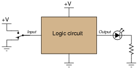
|
|
Notes:
While this may seem to be a very elementary question, it is important to get students to realize just what logic states are, in their physical representations. Too often I read textbooks and other digital logic tutorials that leap the student immediately into a boolean analysis of gate circuits, with everything operating off of abstract 0's and 1's (or "low's" and "high's"), without properly introducing the electrical nature of these states to students. Remember, your students should be quite familiar with electrical circuits, including analog transistor and op-amp circuits, by now, so beginning their study of gates from an electrical perspective should be natural for them. Only after they realize how logic states are represented by voltages do I recommend discussing gates and truth tables.