Digital communication
Question 1:
| Don't just sit there! Build something!! |
Learning to analyze digital circuits requires much study and practice. Typically, students practice by working through lots of sample problems and checking their answers against those provided by the textbook or the instructor. While this is good, there is a much better way.
You will learn much more by actually building and analyzing real circuits, letting your test equipment provide the änswers" instead of a book or another person. For successful circuit-building exercises, follow these steps:
- 1.
- Draw the schematic diagram for the digital circuit to be analyzed.
- 2.
- Carefully build this circuit on a breadboard or other convenient medium.
- 3.
- Check the accuracy of the circuit's construction, following each wire to each connection point, and verifying these elements one-by-one on the diagram.
- 4.
- Analyze the circuit, determining all output logic states for given input conditions.
- 5.
- Carefully measure those logic states, to verify the accuracy of your analysis.
- 6.
- If there are any errors, carefully check your circuit's construction against the diagram, then carefully re-analyze the circuit and re-measure.
Always be sure that the power supply voltage levels are within specification for the logic circuits you plan to use. If TTL, the power supply must be a 5-volt regulated supply, adjusted to a value as close to 5.0 volts DC as possible.
One way you can save time and reduce the possibility of error is to begin with a very simple circuit and incrementally add components to increase its complexity after each analysis, rather than building a whole new circuit for each practice problem. Another time-saving technique is to re-use the same components in a variety of different circuit configurations. This way, you won't have to measure any component's value more than once.
Notes:
It has been my experience that students require much practice with circuit analysis to become proficient. To this end, instructors usually provide their students with lots of practice problems to work through, and provide answers for students to check their work against. While this approach makes students proficient in circuit theory, it fails to fully educate them.
Students don't just need mathematical practice. They also need real, hands-on practice building circuits and using test equipment. So, I suggest the following alternative approach: students should build their own "practice problems" with real components, and try to predict the various logic states. This way, the digital theory "comes alive," and students gain practical proficiency they wouldn't gain merely by solving Boolean equations or simplifying Karnaugh maps.
Another reason for following this method of practice is to teach students scientific method: the process of testing a hypothesis (in this case, logic state predictions) by performing a real experiment. Students will also develop real troubleshooting skills as they occasionally make circuit construction errors.
Spend a few moments of time with your class to review some of the "rules" for building circuits before they begin. Discuss these issues with your students in the same Socratic manner you would normally discuss the worksheet questions, rather than simply telling them what they should and should not do. I never cease to be amazed at how poorly students grasp instructions when presented in a typical lecture (instructor monologue) format!
I highly recommend CMOS logic circuitry for at-home experiments, where students may not have access to a 5-volt regulated power supply. Modern CMOS circuitry is far more rugged with regard to static discharge than the first CMOS circuits, so fears of students harming these devices by not having a "proper" laboratory set up at home are largely unfounded.
A note to those instructors who may complain about the "wasted" time required to have students build real circuits instead of just mathematically analyzing theoretical circuits:
What is the purpose of students taking your course?
If your students will be working with real circuits, then they should learn on real circuits whenever possible. If your goal is to educate theoretical physicists, then stick with abstract analysis, by all means! But most of us plan for our students to do something in the real world with the education we give them. The "wasted" time spent building real circuits will pay huge dividends when it comes time for them to apply their knowledge to practical problems.
Furthermore, having students build their own practice problems teaches them how to perform primary research, thus empowering them to continue their electrical/electronics education autonomously.
In most sciences, realistic experiments are much more difficult and expensive to set up than electrical circuits. Nuclear physics, biology, geology, and chemistry professors would just love to be able to have their students apply advanced mathematics to real experiments posing no safety hazard and costing less than a textbook. They can't, but you can. Exploit the convenience inherent to your science, and get those students of yours practicing their math on lots of real circuits!
Question 2:
Explain the difference between serial digital data and parallel digital data.
Notes:
Ask your students of they have ever heard of ßerial" and "parallel" ports on personal computers. If time permits, have them examine the two types of ports on the back of a PC, contrasting the number of pins used for each connector.
Question 3:
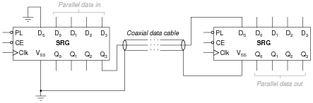
The following schematic diagram shows two four-bit universal shift registers used to communicate data serially over a coaxial cable of unspecified length:
|
|
Specify what logic states would have to be input at the PL, CE, and Clk terminals of each shift register, and at what times, to successfully load four bits of parallel data, shift them serially over the coaxial data cable, and then hold them at the outputs (Q) of the receiving shift register.
- �
- De-activate the clock enable (CE) inputs of both shift registers.
- �
- Apply the four desired bits (logic levels) to the D0 through D3 inputs of the left-hand shift register.
- �
- Briefly activate the parallel load (PL) input of the left-hand shift register.
- �
- Activate the clock enable (CE) inputs of both shift registers simultaneously for four clock pulses.
- �
- etc.
- �
- etc. . . .
Notes:
This question asks students to think their way through the operation of two coupled shift registers to accomplish the task of parallel-to-serial-to-parallel data conversion. Not only is this a good review of shift register operation, but it shows some (not all!) of what happens during the seemingly simple procedure of sending four bits of data in serial form over a cable.
A challenging detail to figure out in this scheme is how to keep both shift registers synchronized so that one receives the serial data bits at the same time the other sends them. There is more than one way to do this, of course, but the easiest would be to connect the two clock inputs together through another cable conductor.
Question 4:
Personal computers and peripheral devices provide a rich source of examples for both serial and parallel data transmission. Identify some common examples of both serial and parallel data transmission networks (and standards) at work in a common personal computer. Examples may include communication between computers, between computers and peripheral devices (printers, scanners, cameras, special cards), or between fundamental components of the computer (CPU, disk drive, monitor, etc.).
Notes:
As computer-savvy as most young students are, questions such as these tend to evoke ready responses and strong interest. You may find that little effort is required on your part to introduce these technologies to your students, as they may be more familiar with certain areas and features of it than you!
Question 5:
A ubiquitous example of serial data communication is the cable linking a keyboard to a personal computer: for every key switch pressed, an ASCII character is transmitted to the computer. An interesting characteristic of this particular communication protocol is the random rate at which the ASCII characters are sent. Because the characters are generated at the rate the computer user happens to type, the rate is completely unpredictable. Consequently, this form of serial data communication is known as asynchronous.
Compare and contrast this against synchronous serial data communication, giving an example of a synchronous data communications standard.
Challenge question: the data sent between computers along serial-format networks such as RS-232C and Ethernet is "clocked" by precise oscillators at both the transmitting and receiving ends, yet is not considered ßynchronous," even if each byte of data is sent at regular (non-random) intervals. Explain why.
Notes:
At first, it seems as though any communication between digital devices occurring at a pre-determined frequency (bps) and rate (characters per second) would be synchronous, because everything is happening on fixed intervals. However, the precision inherent to a true synchronous communications network is more rigorous than this. Let your students elaborate on what they have found through their research.
Question 6:
An important integrated circuit (IC) used in digital data communication is a UART. Describe what this acronym stands for, and explain the purpose of this circuit.
Follow-up question: give an example of a UART IC available for purchase today.
Notes:
When students research what a UART is, they will invariably stumble upon terms such as parity, start bit, and stop bit. If they are not yet familiar with the details of asynchronous data communications, this could lead to some enlightening discoveries. Be sure to discuss these terms and details with your students if they bring them up in class, because it means they will be very receptive to your instruction (having been "primed" for learning by wanting to know).
Question 7:
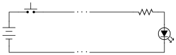
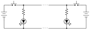
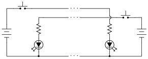
Shown here are three different telegraph circuits. Determine which of these could be classified as simplex, full-duplex, and half-duplex, in terms of serial data transmission:
|
|
|
|
|
|
- �
- Simplex: one-way communication
- �
- Half-duplex: two-way communication, one way at a time.
- �
- Full-duplex: two-way communication, both ways simultaneously.
Follow-up question: trace all currents in these circuits using conventional flow, and then electron flow.
Notes:
I could have just asked for definitions here, but relating these concepts to real circuits, however simple, carries with it more educational benefit. It is also important to show students that the basic concept of digital communication is really no more complex than the old telegraph, just faster.
Question 8:
An early form of digital, serial data communication was Morse code. Explain what "Morse code" is (or was), and how it compares to more modern codes such as ASCII.
Notes:
An interesting feature of Morse code likely not recognized by your students is inherent compression. Because some Morse characters are shorter than others (fewer pulses) as opposed to ASCII where all characters are the same length, messages sent in Morse tend to require fewer bits than messages sent in ASCII.
Question 9:
An important performance parameter of digital communications networks is the number of bits per second (bps) of data it can handle. Unfortunately, a different term called baud is often used interchangeably with bps. Define what "baud" is, and how it differs from "bits per second."
Notes:
While some may argue the difference to be academic, I believe that precision of language and precision of thinking are closely related. The person who does not recognize the difference between "baud" and "bps" most likely knows little about how digital information is encoded for serial transmission. Of course, this is the ultimate issue - understanding how digital data is transmitted. So while we're at it, we might as well address a common mis-use of language and gain a deeper understanding of how things work, right?
Question 10:
In Claude Shannon's famous 1948 paper entitled A Mathematical Theory of Communication, he opens with the following statement:
- "The recent development of various methods of modulation such as PCM and PPM which exchange bandwidth for signal-to-noise ratio has intensified the interest in a general theory of communication."
Notes:
Shannon's language is perhaps a bit above the norm for technician-level education, but it nevertheless captures an important quality of digital communication: that the noise immunity enjoyed by digital communication comes at a price: high bandwidth. Without a high-bandwidth medium in which to exchange digital information, communication is either slow or completely impractical.