Basic electromagnetism and electromagnetic induction
Question 1:
When lightning strikes, nearby magnetic compass needles may be seen to jerk in response to the electrical discharge. No compass needle deflection results during the accumulation of electrostatic charge preceding the lightning bolt, but only when the bolt actually strikes. What does this phenomenon indicate about voltage, current, and magnetism?
Notes:
The discovery of electromagnetism was nothing short of revolutionary in Oersted's time. It paved the way for the development of electric motors, among other useful electrical devices.
Question 2:
Just as electricity may be harnessed to produce magnetism, magnetism may also be harnessed to produce electricity. The latter process is known as electromagnetic induction. Design a simple experiment to explore the phenomenon of electromagnetic induction.
Notes:
Many students improperly assume that electromagnetic induction may take place in the presence of static magnetic fields. This is not true. The simple experimental setup described in the Änswer" section for this question is sufficient to dispel that myth, and to illuminate students' understanding of this principle. Incidentally, this activity is a great way to get students started thinking in calculus terms: relating one variable to the rate of change over time of another variable.
Question 3:
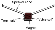
A large audio speaker may serve to demonstrate both the principles of electromagnetism and of electromagnetic induction. Explain how this may be done.
|
|
The "voice coil" is attached to the flexible speaker cone, and is free to move along the long axis of the magnet. The magnet is stationary, being solidly anchored to the metal frame of the speaker, and is centered in the middle of the voice coil.
This experiment is most impressive when a physically large (i.e. "woofer") speaker is used.
Follow-up question: identify some possible points of failure in a speaker which would prevent it from operating properly.
Notes:
Since not everyone has ready access to a large speaker for this kind of experiment, it may help to have one or two "woofer" speakers located in the classroom for students to experiment with during this phase of the discussion. Any time you can encourage students to set up impromptu experiments in class for the purpose of exploring fundamental principles, it is a Good Thing.
Question 4:
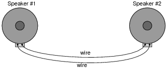
What do you think might happen if someone were to gently tap on the cone of one of these speakers? What would the other speaker do? In terms of electromagnetism and electromagnetic induction, explain what is happening.
|
|
Notes:
Not only does this experiment illustrate the dual principles of electromagnetism and electromagnetic induction, but it also demonstrates how easy it is to set up a simple sound-powered audio telephony system.
It is highly recommended to have an identical pair of "woofer" speakers located in the classroom for this experiment, as well as a long length of twin-wire cable (an old piece of extension cord wire works well for this purpose, with alligator-clip "jumper" wires to make the connections).
Question 5:
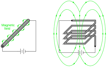
Draw the pattern of the magnetic field produced by electric current through a straight wire and through a wire coil:

|
|
Explain your answer using either the right-hand rule (conventional flow) or the left-hand rule (electron flow).
|
|
Notes:
In your students' research, they will encounter a "right-hand rule" as well as a "left-hand rule" for relating electric current with magnetic field directions. The distinction between the two rules depends on whether the text uses "conventional flow" notation or ëlectron flow" notation to denote the movement of electrical charge through the conductors. Sadly, this is another one of those concepts in electricity that has been made unnecessarily confusing by the prevalence of two ßtandard" notions for electric current.
Question 6:
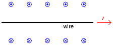
When engineers and physicists draw pictures illustrating the magnetic field produced by a straight current-carrying wire, they usually do so using this notation:
|
|
Explain what the circle-and-dot and circle-and-cross symbols mean, with reference to the right-hand rule.
Notes:
As a follow-up to this question, you might wish to draw current-carrying wires at different angles, and with current moving in different directions, as practice problems for your students to draw the corresponding arrow points and tails.
Question 7:
In 1820, the French physicist André Marie Ampère discovered that two parallel wires carrying electrical current would either be attracted to one another, or repelled by one another, depending on what directions the two currents were going. Devise an experiment to reproduce Ampère's results, and determine which directions current must go to produce an attractive versus a repulsive force.
Notes:
This experiment is well worth performing during discussion time with your students. There are several ways to demonstrate the effect of electromagnetism in the way that Ampère did back in 1820. It will be interesting to compare your students' different approaches to this experiment.
One of the habits you should encourage in your students is experimentation to discover or confirm principles. While researching other peoples' findings is a valid mode to obtaining knowledge, the rewards of primary research (i.e. direct experimentation) are greater and the results more authoritative.
Another point you might want to mention here is the problem-solving technique of altering the problem. Instead of envisioning two straight parallel wires, imagine those wires being bent so they form two parallel coils. Now the right-hand rule applies for determining magnetic polarity, and the question of attraction versus repulsion is more easily answered.
Question 8:
A permanent magnet is a device that retains a magnetic field without need for a power source. Though many of us have experienced the effects of magnetism from a permanent magnet, very few people can describe what causes permanent magnetism. Explain the cause of permanent magnetism, in your own words.
Follow-up question: what does the term retentivity mean, in relation to permanent magnetism?
Notes:
The answers students find to this question may be philosophically unsatisfying. It is one thing to discover that magnetism is produced by moving electric charges, but quite another to discover (much less explain) just what a magnetic field is in an ontological sense. Sure, it is easy to explain what magnetic fields do, or even how they relate to other phenomenon. But what, exactly, is a magnetic field? This question is on the same level as, "what is an electric charge?"
Question 9:
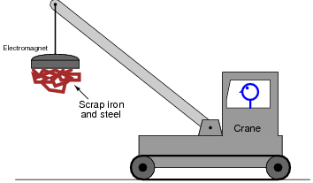
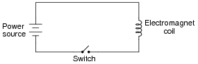
Cranes used to move scrap iron and steel use electrically powered magnets to hold the metal pieces, rather than a scoop or some other mechanical grasping device:
|
|
In this illustration of a crane, superimpose a drawing showing the electromagnet, electrical power supply and wiring necessary for this to work. Also include a switch so the crane operator can turn the magnet on and off. Also, draw an electrical schematic diagram of the same circuit, showing all components in the crane's magnet circuit.
|
|
I will leave it to you to draw the illustration of this circuit on the crane. Your answer should show a wire coil embedded in the electromagnet assembly, a switch symbol near the operator, a battery symbol for the power supply, and wires carrying current to and from the electromagnet coil.
Notes:
The main purpose of this question is to have the students relate the principles of electric circuits and electromagnetism to a real-life application, and to show how the wire paths in the crane do not resemble the neat, clean layout of the schematic diagram.
Question 10:
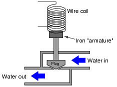
A solenoid valve uses magnetism from an electromagnet coil to actuate a valve mechanism:
|
|
Essentially, this is an electrically-controlled on/off water valve. In the development of this valve, though, the design engineers discover that the magnetic force produced by the electromagnet coil is not strong enough to achieve reliable valve actuation every time. What can be changed in this solenoid valve design to produce a greater actuating force?
Follow-up question: suppose this valve did not open like it was supposed to when the solenoid coil was energized. Identify some possible reasons for this type of failure.
Notes:
The fundamental question here is, "what factors influence the strength of an electromagnetically-generated magnetic field?" It is easy to research the effects of coil dimensions, core materials, current levels, etc. What students need to do in this question is apply those techniques to this real-life scenario.
Be sure to spend time on the follow-up question with your students, considering non-electrical as well as electrical fault possibilities.
Question 11:
A coil of wire is formed of many loops. These loops, though tracing a circular path, may be thought of as being parallel to each other. We know that whenever two parallel wires carry an electric current, there will be a mechanical force generated between those two wires (as in André Marie Ampère's famous experiment).
When electric current is passed through a coil of wire, does the inter-loop force tend to compress the coil or extend it? Explain your answer.
Challenge question: what will happen to a wire coil if alternating current is passed through it instead of direct current? Will the coil compress, extend, or do something entirely different?
Notes:
Questions such as this require the student to visualize a "bent" version of a phenomenon defined in terms of straight wires (Ampére's experiment). Some students, of course, will have a much more difficult time visualizing this than others. For those that struggle with this form of problem-solving, spend some discussion time on problem-solving (visualization) techniques to help those who find this difficult to do. Is there a particular drawing, sketch, or analogy that other students have found useful in their analysis of the problem?
The challenge question regarding alternating current is meant to be a "trick" question of sorts. The ünthinking" answer is that with alternating current, there will be a force that alternates direction: repulsion one half-cycle, then attraction for the next half-cycle. You may find students divided on this assessment, some thinking there will an alternating force, while others think the force will remain in the same direction at all times. There is one sure way to prove who is correct here: set up an experiment with AC power and see for yourself (straight, parallel wires will work just fine for this)!
Question 12:
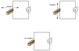
Which magnet motion past the wire will produce the greatest voltmeter indication: perpendicular, parallel, or no motion at all?
|
|
Hint: the voltage generated by a magnetic field with a single wire is quite weak, so I recommend using a very sensitive voltmeter and/or a powerful magnet. Also, if the meter is analog (has a moving pointer and a scale rather than a digital display), you must keep it far away from the magnet, so that the magnet's field does not directly influence the pointer position.
Follow-up question: identify some potential problems which could arise in this experiment to prevent induction from occurring.
Notes:
This is another one of those concepts that is better learned through experimentation than by direct pronouncement, especially since the experiment itself is so easy to set up.