Intermediate electromagnetism and electromagnetic induction
Question 1:
As an electric current is passed through a coil of wire, it creates a magnetic field. If the magnitude of this current changes over time, so will the strength of the magnetic field.
We also know that a magnetic field flux that changes over time will induce a voltage along the length of a wire coil. Explain how the complementary principles of electromagnetism and electromagnetic induction manifest themselves simultaneously in the same wire coil to produce self-induction.
Also, explain how Lenz's Law relates to the polarity of the coil's self-induced voltage.
Notes:
Self-induction is not a difficult concept to grasp if one already possesses a good understanding of electromagnetism, electromagnetic induction, and Lenz's Law. Some students may struggle understanding self-induction, because it is probably the first application they've seen where these three phenomena inter-relate simultaneously.
Question 2:
|
�f(x) dx Calculus alert! |
|
|
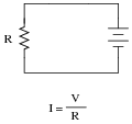
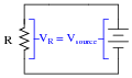
Although an analysis of this circuit probably seems trivial to you, I would like to encourage you to look at what is happening here from a fresh perspective. An important principle observed many times in the study of physics is that of equilibrium, where quantities naturally ßeek" a state of balance. The balance sought by this simple circuit is equality of voltage: the voltage across the resistor must settle at the same value as the voltage output by the source:
|
|
If the resistor is viewed as a source of voltage seeking equilibrium with the voltage source, then current must converge at whatever value necessary to generate the necessary balancing voltage across the resistor, according to Ohm's Law (V = IR). In other words, the resistor's current achieves whatever magnitude it has to in order to generate a voltage drop equal to the voltage of the source.
This may seem like a strange way of analyzing such a simple circuit, with the resistor ßeeking" to generate a voltage drop equal to the source, and current "magically" assuming whatever value it must to achieve that voltage equilibrium, but it is helpful in understanding other types of circuit elements.
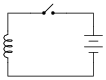
For example, here we have a source of DC voltage connected to a large coil of wire through a switch. Assume that the wire coil has negligible resistance (0 W):
|
|
Like the resistor circuit, the coil will ßeek" to achieve voltage equilibrium with the voltage source once the switch is closed. However, we know that the voltage induced in a coil is not directly proportional to current as it is with a resistor - instead, a coil's voltage drop is proportional to the rate of change of magnetic flux over time as described by Faraday's Law of electromagnetic induction:
|
Where,
vcoil = Instantaneous induced voltage, in volts
N = Number of turns in wire coil
[(d f)/dt] = Instantaneous rate of change of magnetic flux, in webers per second
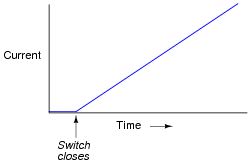
Assuming a linear relationship between coil current and magnetic flux (i.e. f doubles when i doubles), describe this simple circuit's current over time after the switch closes.
|
|
Challenge question: real wire coils contain electrical resistance (unless they're made of superconducting wire, of course), and we know how voltage equilibrium occurs in resistive circuits: the current converges at a value necessary for the resistance to drop an equal amount of voltage as the source. Describe, then, what the current does in a circuit with a real wire coil, not a superconducting wire coil.
Notes:
Students who do not yet understand the concept of inductance may be inclined to suggest that the current in this circuit will be infinite, following Ohm's Law (I = E/R). One of the purposes of this question is to reveal such misunderstandings, so that they may be corrected.
This circuit provides an excellent example of the calculus principle integration, where the application of a steady voltage across the inductor results in a steadily increasing current. Whether or not you should touch on this subject depends on the mathematical aptitude of your students.
Question 3:
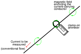
A very useful method of measuring current through a wire is to measure the strength of the magnetic field around it. This type of ammeter is known as a clamp-on ammeter:
|
|
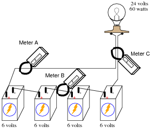
Knowing the principle behind this meter's operation, describe what current values will be indicated by the three clamp-on ammeters in this circuit:
|
|
- �
- Meter A =
- �
- Meter B =
- �
- Meter C =
- �
- Meter A = 2.5 amps
- �
- Meter B = 2.5 amps
- �
- Meter C = 0 amps
Notes:
Clamp-on meters are very useful pieces of test equipment, but they must be used properly. I have seen many people make the mistake of clamping one of these ammeters around multiple wires when trying to measure the amount of current through only one. If you have any clamp-on meters in your classroom, have your students set up a simple circuit like this and prove the validity of the concept.
Question 4:
Write an equation that expresses the amount of magnetic flux (F) produced by an electromagnet, given the amount of electric current (I), the number of turns in the wire coil (N), and the reluctance of the core material (�).
|
Notes:
This is an exercise in algebraic substitution. Students are not likely to find this equation anywhere, so they'll have to create it from a combination of two other equations.
Question 5:
|
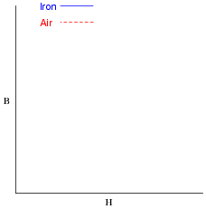
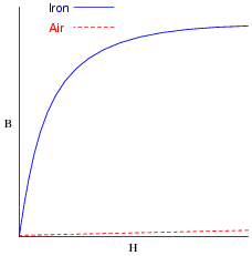
Plot the relative B-H curves for a sample of air and a sample of iron, in proportion to each other (as much as possible):
|
|
What do you notice about the slope (also called the derivative, or [dB/dH]) of each plot?
|
|
Follow-up question: note that the slope of both plots are approximately equal toward the far right end of the graph. Explain this effect in terms of magnetic saturation.
Notes:
The purpose of this question is twofold: to get students to see that a ferromagnetic material such as iron is much more permeable (less "reluctant") than air, but that the great gains in B realized by iron tend to disappear as soon as saturation sets in. Once the iron is saturated, the gains in B for equal advances in H are the same as for air. That is, the [dB/dH] for iron is equal to the [dB/dH ] for air once the iron is saturated.
Question 6:
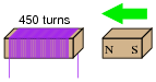
If a wire coil with 450 turns is exposed to a magnetic flux increasing at a rate of 0.008 Webers per second, how much voltage will be induced across the coil?
|
|
Notes:
This is simply a quantitative application of Faraday's Law. There is no significance to the fact that the magnetic flux is increasing rather than decreasing. The only effect this would have on the induced voltage is its polarity.
Question 7:
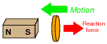
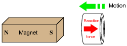
Lenz's Law describes the opposition to changes in magnetic flux resulting from electromagnetic induction between a magnetic field and an electrical conductor. One apparatus capable of demonstrating Lenz's Law is a copper or aluminum disk (electrically conductive, but non-magnetic) positioned close to the end of a powerful permanent magnet. There is no attraction or repulsion between the disk and magnet when there is no motion, but a force will develop between the two objects if either is suddenly moved. This force will be in such a direction that it tries to resist the motion (i.e. the force tries to maintain the gap constant between the two objects):
|
|
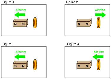
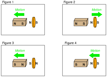
We know this force is magnetic in nature. That is, the induced current causes the disk itself to become a magnet in order to react against the permanent magnet's field and produce the opposing force. For each of the following scenarios, label the disk's induced magnetic poles (North and South) as it reacts to the motion imposed by an outside force:
|
|
|
|
Follow-up question: trace the direction of rotation for the induced electric current in the disk necessary to produce both the repulsive and the attractive force.
Notes:
This phenomenon is difficult to demonstrate without a very powerful magnet. However, if you have such apparatus available in your lab area, it would make a great piece for demonstration!
One practical way I've demonstrated Lenz's Law is to obtain a rare-earth magnet (very powerful!), set it pole-up on a table, then drop an aluminum coin (such as a Japanese Yen) so it lands on top of the magnet. If the magnet is strong enough and the coin is light enough, the coin will gently come to rest on the magnet rather than hit hard and bounce off.
A more dramatic illustration of Lenz's Law is to take the same coin and spin it (on edge) on a table surface. Then, bring the magnet close to the edge of the spinning coin, and watch the coin promptly come to a halt, without contact between the coin and magnet.
Another illustration is to set the aluminum coin on a smooth table surface, then quickly move the magnet over the coin, parallel to the table surface. If the magnet is close enough, the coin will be "dragged" a short distance as the magnet passes over.
In all these demonstrations, it is significant to show to your students that the coin itself is not magnetic. It will not stick to the magnet as an iron or steel coin would, thus any force generated between the coin and magnet is strictly due to induced currents and not ferromagnetism.
Question 8:
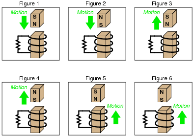
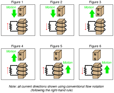
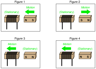
Combining Lenz's Law with the right-hand rule (or left-hand rule, if you follow electron flow instead of conventional flow) provides a simple and effective means for determining the direction of induced current in an induction coil. In the following examples, trace the direction of current through the load resistor:
|
|
|
|
Notes:
An easy way I find to remember Lenz's Law is to interpret is as opposition to change. The coil will try to become a magnet that fights the motion. A good way to get students thinking along these lines is to ask them, "What magnetic polarity would the coil have to assume (in each case) to resist the magnet's relative motion?" In other words, if the magnet moves closer to the coil, the coil will "magnetize" so as to push against the magnet. If the magnet moves away from the coil, the coil will "magnetize" so as to attract the magnet.
Question 9:
Write the equation relating electric current and magnetic field strength together in a wire coil. If the current (I) is given in units of amperes, and the number of turns is a simple integer value, what unit of measurement will the magnetic field strength have?
|
Where,
F = Magnetomotive force (magnetic field strength), in amp-turns
I = Current in wire coil, amps
N = Number of turns in coil
Notes:
Sometimes, units of measurement make perfect sense! In this case, the unit of the amp-turn follows obviously from the construction of the equation, with amps times turns.
Question 10:
What is magnetic saturation?
Notes:
To use an economic phrase, saturation is a case of diminishing returns: where further increases in one variable yield smaller and smaller gains in another variable. It is important that students recognize the word ßaturation" is used to describe phenomena other than magnetism, as well. But in any context it is used, the "diminishing returns" concept is the same.
Question 11:
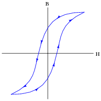
Explain what this graph means, and how it represents both saturation and hysteresis as magnetic phenomena:
|
|
"Saturation" is when B changes little for substantial changes in H. There are two regions on the B-H curve where saturation is evident.
Notes:
This question is worthy of much discussion. It is one thing to recognize this curve as being a B-H curve, and quite another to explain exactly what it means. Ask your students to show on the curve, for instance, what happens when an electromagnet is fully energized with DC, and then the current is shut off, leaving a residual flux in the core. What is necessary to de-magnetize the core once again?
Also be sure to discuss saturation in detail. This is a very important magnetic phenomenon, without a direct analogy in electric circuits (it is not as though wires ßaturate" when carrying too much current!).
Question 12:
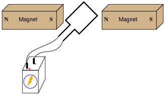
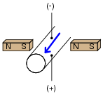
If an electric current is passed through this wire loop, in which position will it try to orient itself?
|
|
If this experiment is carried out, it may be found that the torque generated is quite small without resorting to high currents and/or strong magnetic fields. Devise a way to modify this apparatus so as to generate stronger torques using modest current levels and ordinary magnets.
|
|
To increase the torque generated by the wire loop, you could use a loop with more than 1 "turn" of wire. This is not the only solution, though.
Notes:
This question presents an excellent opportunity for discussing the "right-hand rule" (or "left-hand rule" for those using electron flow notation rather than conventional flow notation).
Question 13:
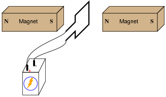
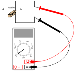
By moving a permanent magnet perpendicularly past a wire, a voltage will be generated between the ends of that wire:
|
|
Describe what factors determine the polarity and magnitude of this voltage.
Notes:
Experiments like this are so easy to set up, it would be a shame to spoil the joy of firsthand discovery by simply telling students what is supposed to happen!
Question 14:
|
The relationship between magnetic flux and induced voltage in a wire coil is expressed in this equation, known as Faraday's Law:
|
Where,
e = Instantaneous induced voltage, in volts
N = Number of turns in wire coil
f = Instantaneous magnetic flux, in webers
t = Time, in seconds
Explain what the mathematical expression [(d f)/dt] means, in light of what you know about electromagnetic induction. Hint: the [d/d] notation is borrowed from calculus, and it is called the derivative.
Also, explain why lower-case letters are used (e instead of E, f instead of F) in this equation.
The use of lower-case letters for variables indicates instantaneous values: that is, quantities expressed in terms of instantaneous moments of time.
Follow-up question: manipulate this equation to solve for each variable ([(d f)/dt] = � ; N = �).
Notes:
For students who have never studied calculus, this is an excellent opportunity to introduce the concept of the derivative, having already established the principle of induced voltage being related to how quickly magnetic flux changes over time. In general physics studies, the quantities of position, velocity, and acceleration are similarly used to introduce the concept of the time-derivative, and later, the time-integral. In electricity, though, we have our own unique applications!
Question 15:
How many turns of wire must a coil have in order to induce a voltage of 10.5 volts when exposed to a changing magnetic flux with a rate of 0.0075 Wb/s?
Notes:
This is nothing but a quantitative application of Faraday's Law, after algebraic manipulation to solve for N.
Question 16:
If a copper ring is brought closer to the end of a permanent magnet, a repulsive force will develop between the magnet and the ring. This force will cease, however, when the ring stops moving. What is this effect called?
|
|
Also, describe what will happen if the copper ring is moved away from the end of the permanent magnet.
Follow-up question: trace the direction of rotation for the induced electric current in the ring necessary to produce both the repulsive and the attractive force.
Challenge question: what would happen if the magnet's orientation were reversed (south pole on left and north pole on right)?
Notes:
This phenomenon is difficult to demonstrate without a very powerful magnet. However, if you have such apparatus available in your lab area, it would make a great piece for demonstration!
One practical way I've demonstrated Lenz's Law is to obtain a rare-earth magnet (very powerful!), set it pole-up on a table, then drop an aluminum coin (such as a Japanese Yen) so it lands on top of the magnet. If the magnet is strong enough and the coin is light enough, the coin will gently come to rest on the magnet rather than hit hard and bounce off.
A more dramatic illustration of Lenz's Law is to take the same coin and spin it (on edge) on a table surface. Then, bring the magnet close to the edge of the spinning coin, and watch the coin promptly come to a halt, without contact between the coin and magnet.
Another illustration is to set the aluminum coin on a smooth table surface, then quickly move the magnet over the coin, parallel to the table surface. If the magnet is close enough, the coin will be "dragged" a short distance as the magnet passes over.
In all these demonstrations, it is significant to show to your students that the coin itself is not magnetic. It will not stick to the magnet as an iron or steel coin would, thus any force generated between the coin and magnet is strictly due to induced currents and not ferromagnetism.
Question 17:
Electromechanical watt-hour meters use an aluminum disk that is spun by an electric motor. To generate a constant "drag" on the disk necessary to limit its rotational speed, a strong magnet is placed in such a way that its lines of magnetic flux pass perpendicularly through the disk's thickness:
|
|
Explain the phenomenon behind this magnetic "drag" mechanism, and also explain how the permanent magnet assembly should be re-positioned so that it provides less drag on the disk for the same rotational speed.
Follow-up question: suppose you move a strong magnet past the surface of an aluminum disk. What will happen to the disk, if anything?
Notes:
An important calibration adjustment on electromechanical wattmeter assemblies is the positioning of the "drag" magnet, making this question a very practical one. An interesting challenge for students is to ask them to sketch the flow of induced electric current in the disk as it rotates past the magnet!
The follow-up question is actually a preview of induction motor theory, and may be illustrated with a powerful (rare-earth) magnet and a metal coin (Japanese Yen, made of aluminum, work very well for this, being good electrical conductors and lightweight!).
Question 18:
One context in which to understand Lenz's Law is the well-known physical law called the Conservation of Energy, which states that energy can neither be created (from nothing) nor destroyed (to nothing). This well-founded law of physics is the general principle forbidding so-called över-unity" or "free energy" machines, where energy would supposedly be produced from no source whatsoever.
Demonstrate that if Lenz's Law were reversed, the Conservation of Energy principle would be violated. In other words, imagine what would happen if the effects of Lenz's Law were exactly opposite in direction, and show how this would result in more energy produced by a system than what is input to that system.
Notes:
This question may very well lead to a fruitful discussion on perpetual motion and claims of "free energy" machines, the very existence of such claims in modern times being outstanding evidence of scientific illiteracy. Not only do a substantial number of people seem ignorant of the Conservation of Energy principle and just how well it is founded, but also seem unable to grasp the importance of the ultimate test for such a device: to be able to power itself (and a load) indefinitely. But I digress . . .
Question 19:
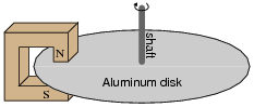
Based on your knowledge of Lenz's Law, explain how one could construct an electromagnetic brake, whereby the energization of an electromagnet coil would produce mechanical "drag" on a rotating shaft without the need for contact between the shaft and a brake pad.
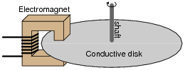
|
|
Follow-up question: describe some of the advantages and disadvantages that a magnetic brake would have, compared to mechanical brakes (where physical contact produces friction on the shaft).
Challenge question: normal (mechanical) brakes become hot during operation, due to the friction they employ to produce drag. Will an electromechanical brake produce heat as well, given that there is no physical contact to create friction?
Notes:
Electromagnetic brakes are very useful devices in industry. One interesting application I've seen for this technology is the mechanical load for an automotive dynamometer, where a car is driven onto a set of steel rollers, with one roller coupled to a large metal disk (with electromagnets on either side). By varying the amount of current sent to the electromagnets, the degree of mechanical drag may be varied.
Incidentally, this disk becomes very hot when in use, because the automobile's power output cannot simply vanish - it must be converted into a different form of energy in the braking mechanism, and heat it is.
Question 20:
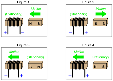
Determine the polarity of the coil's induced voltage for each of the following examples. Be careful to note the direction each coil is wrapped around its core - the coils are not all identical!
|
|
|
|
Notes:
It might help students to visualize the polarity if they imagine a resistive load connected between the two output terminals, and then figured out which direction induced current would go through that load. Once that determination is made, voltage polarity (considering the coil as an energy source) should be easier to visualize. A mistake many beginning students make when doing this, though, is to fail to recognize the coil as the source of electrical energy and the resistor as the load, so be prepared to address this misunderstanding.
If this does not help, suggest they first identify the magnetic polarity of the coil's induced field: determine which end of the coil is "trying" to be North and which is "trying" to be South. Of course, no induced field will form unless the coil has a complete circuit to sustain the induced current, but it is still helpful to imagine a load resistor or even a short completing the circuit so that induced current and thus induced magnetic polarity may be visualized.
Question 21:
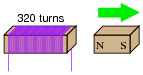
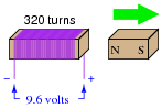
If a wire coil with 320 turns is exposed to a magnetic flux decreasing at a rate of 0.03 Webers per second (as shown in the illustration), how much voltage will be induced across the coil, and what will its polarity be?
|
|
|
|
Notes:
This question is both a quantitative application of Faraday's Law and an application of Lenz's Law.
Question 22:
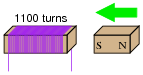
If a wire coil with 1100 turns is exposed to a magnetic flux increasing at a rate of 0.07 Webers per second (as shown in the illustration), how much voltage will be induced across the coil, and what will its polarity be?
|
|
|
|
Notes:
This question is both a quantitative application of Faraday's Law and an application of Lenz's Law.
Question 23:
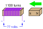
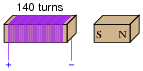
Calculate the necessary magnetic flux rate-of-change over time (in units of Webers per second) as well as the direction of magnet motion (either toward or away from the coil) to induce a voltage of 13.5 volts in the polarity shown:
|
|
Notes:
This question is both a quantitative application of Faraday's Law and an application of Lenz's Law.
Question 24:
If the motion of a conductor through a magnetic field induces a voltage in that conductor, it stands to reason that a conductive fluid moving through a pipe can also generate a voltage, if properly exposed to a magnetic field. Draw a picture showing the necessary orientation of the pipe, the magnetic field, and the electrodes intercepting the induced voltage.
|
|
Notes:
This question really tests students' comprehension of the orthogonal relationships between magnetic flux, conductor motion, and induced voltage. Additionally, it reveals a novel method of producing electricity: magnetohydrodynamics.
There are a few interesting applications of magnetohydrodynamics, including power generation and flow measurement. Discuss these with your students if time permits.