Encoders and decoders
Question 1:
What does it mean, in general terms, to encode something? Conversely, what does it mean to decode something? Perhaps the most common context for these terms to be used is cryptography (code-making and code-breaking), but they also find application in common digital circuits.
Notes:
This question gets students thinking about encoding and decoding in general terms - terms which they are probably already familiar with. This is a good first step in instruction, to identify a well-known context for a new subject, so students have an easier time relating to it.
Question 2:
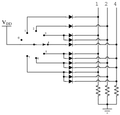
The simple switch-and-diode circuit shown here is an example of a digital encoder. Explain what this circuit does, as the switch is moved from position to position:
|
|
Follow-up question: trace the path of electron flow through the circuit with the switch in position #3.
Challenge question: are there other codes (besides binary) that could possibly be generated with a circuit of this general design?
Notes:
Ask your students to explain how the term ëncoder" applies to this simple circuit. What, exactly, is being encoded, and what form of code is the data being converted to?
Question 3:
Having learned how to build simple encoder circuits using diode networks, you set out to form your own encoder manufacturing company: Encoders, Inc. After agreeing on a policy of truth in advertising, your board of directors drafts this slogan:
|
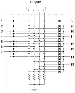
After months of hard work, you unveil your latest masterpiece, the 16-line to 4-line encoder:
|
|
However, your first customer has a complaint with your encoder circuit. He claims it often outputs false codes. After sending it back to your workshop for warranty repair, you determine there is nothing wrong with the encoder circuit itself: it always outputs the correct codes when you energize the appropriate inputs. Perhaps the problem is in how the customer is using it.
You then telephone the customer and ask him how he is using the encoder. He tells you it is used as part of a fault diagnostic circuit for an important piece of machinery. Each input of the encoder is connected to a different sensor on the machine (low oil pressure switch, high temperature switch, out-of-limit travel switches, etc.), and then the encoder outputs drive a four-LED display for maintenance technicians to view. They would have rather used a separate LED for each "trouble" sensor, but the display panel was too small to accommodate fifteen LEDs, so they decided to use four LEDs and an encoder, having their technicians interpret a binary code to determine which of the fifteen sensors is activating.
To the best of your ability, determine why your company's flagship encoder circuit sometimes produces false codes in this application. Then, recommend a solution for your customer.
Notes:
Despite the overly simplistic nature of the company's product, this scenario accurately reflects the realistic nature of product development and customer application. Often, a company designs, builds, and markets a product, and the customers experience trouble because their applications are improper for that product, or the application reveals a deficiency in the product that wasn't detected during development.
As elegant as the "diode network" design of encoder is, it certainly has its limitations. Ask your students whether the output of this encoder circuit will always be incorrect if two inputs are simultaneously activated, or if only particular combinations of active inputs cause problems. Which condition would be easier to troubleshoot?
Discuss alternative solutions with your students, being sure to first define what the problem is so that all understand.
Question 4:
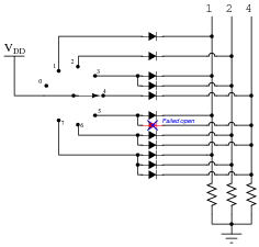
Identify which diode is failed in this circuit, given the following truth table (showing the actual operation of the encoder circuit, not what it should do):

|
|
-
Switch position Output code
0 000
1 001
2 010
3 011
4 100
5 001
6 110
7 111
Be sure to specify whether you think the failed diode is open or shorted.
|
|
Notes:
This question helps students understand the purpose of the diodes in this type of encoder circuit: to steer the power to the appropriate output lines, and only to those lines.
Question 5:
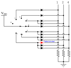
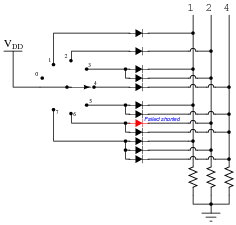
Identify which diode is failed in this circuit, given the following truth table (showing the actual operation of the encoder circuit, not what it should do):

|
|
-
Switch position Output code
0 000
1 111
2 010
3 111
4 100
5 111
6 110
7 111
Be sure to specify whether you think the failed diode is open or shorted.
|
|
Notes:
This question helps students understand the purpose of the diodes in this type of encoder circuit: to steer the power to the appropriate output lines, and only to those lines.
Question 6:
Identify which diode is failed in this circuit, given the following truth table (showing the actual operation of the encoder circuit, not what it should do):

|
|
-
Switch position Output code
0 000
1 001
2 110
3 111
4 100
5 101
6 110
7 111
Be sure to specify whether you think the failed diode is open or shorted.
|
|
Notes:
This question helps students understand the purpose of the diodes in this type of encoder circuit: to steer the power to the appropriate output lines, and only to those lines.
Question 7:
Explain how the following decimal-to-BCD encoder circuit works:
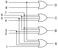
|
|
Also, determine which output (D or A) is the most significant bit of the BCD output.
Follow-up question: what would have to be modified in order to turn this into a hexadecimal-to-binary (16 line to 4 line) encoder? Would any additional OR gates have to be added to the circuit?
Notes:
Non-priority encoder circuits such as this one are fairly simple to figure out, and so I do not provide an explanation for students in the Änswer" section.
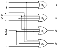
Question 8:
Suppose OR gate U3 were to fail with the output terminal always high. Which output codes would be affected by this fault?
|
|
Notes:
Ask your students to explain how they determined the affected codes. Although the question itself is relatively simple, there is room for creativity in the answers!
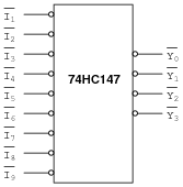
Question 9:
Here is the block symbol for the 74HC147 decimal-to-BCD encoder:
|
|
Describe what sort of input conditions would be required to make it generate the code for the number 7, and how that numerical quantity would be represented on the output (Y) lines.
- �
- Y0 = low
- �
- Y1 = low
- �
- Y2 = low
- �
- Y3 = high
Notes:
This is a good review of active-low inputs, how they are drawn on schematics, and what they mean in practical digital circuits. A potentially confusing aspect of this question is the presence of active-low inputs and outputs, but it is well worth your time to review with students, because like it or not there are many ICs with active-low I/O lines.
Question 10:
What is a priority encoder circuit, and how does it differ from a regular encoder? Find a datasheet for a priority encoder, and explain how the encoder circuit works.
Notes:
Be sure to ask your students where and how they found their respective priority encoder datasheets.
Question 11:
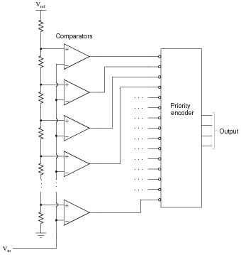
The circuit shown here is a four-bit analog-to-digital converter (ADC). Specifically, it is a flash converter, so named because of its high speed:
|
|
Explain why we must use a priority encoder to encode the comparator outputs into a four-bit binary code, and not a regular encoder. What problem(s) would we have if we were to use a non-priority encoder in this ADC circuit?
Notes:
Here, I show students a very practical application of a priority encoder, in which the necessity of priority encoding should be apparent after some analysis of the circuit.
Question 12:
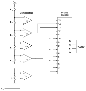
Predict how the operation of this "flash" analog-to-digital converter (ADC) circuit will be affected as a result of the following faults. Consider each fault independently (i.e. one at a time, no multiple faults):
|
|
- �
- Resistor R16 fails open:
- �
- Resistor R1 fails open:
- �
- Comparator U13 output fails low:
- �
- Solder bridge (short) across resistor R14:
For each of these conditions, explain why the resulting effects will occur.
- �
- Resistor R16 fails open: Output code will be 15 (1111) all the time.
- �
- Resistor R1 fails open: If Vin < Vref, output will be 0 (0000); if Vin > Vref, output will be 15 (1111).
- �
- Comparator U13 output fails low: Output will assume the "13" state (1101) unless Vin exceeds that analog value, then the ADC will register properly.
- �
- Solder bridge (short) across resistor R14: There will be no distinctive "13" state (1101), the analog values for all the other states adjusting slightly to fill the gap.
Notes:
The purpose of this question is to approach the domain of circuit troubleshooting from a perspective of knowing what the fault is, rather than only knowing what the symptoms are. Although this is not necessarily a realistic perspective, it helps students build the foundational knowledge necessary to diagnose a faulted circuit from empirical data. Questions such as this should be followed (eventually) by other questions asking students to identify likely faults based on measurements.
Question 13:
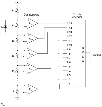
This "flash" ADC circuit has a problem. The output code jumps from 0000 to 1111 with just the slightest amount of input voltage (Vin). In fact, the only time it outputs 0000 is when the input terminal is slightly negative with reference to ground:
|
|
Identify at least two possible component faults that could cause this problem, and explain your reasoning in how you made the identifications.
Notes:
Have your students explain their reasoning in class to you, so that you may observe their diagnostic thought processes.
Question 14:
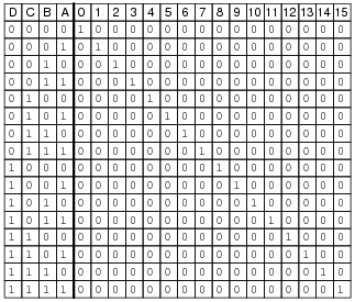
The truth table shown here is for a 4-line to 16-line binary decoder circuit:
|
|
For each of the sixteen output lines, there is a Boolean SOP expression describing its function. Just for example, write the Boolean expressions for output lines 5, 8, and 13.
Output line 8: [`A] [`B] [`C] D
Output line 13: A[`B]CD
Follow-up question: based on what you see here, what kind of logic gate circuitry is a decoder such as this comprised of? You don't have to actually draw a schematic diagram, but just generally describe the circuitry necessary to implement sixteen different SOP expressions.
Notes:
Nothing really complex or tricky here. Just a straightforward application of Boolean SOP expressions.
Question 15:
The truth table shown here is for a 4-line to 16-line binary decoder circuit:

|
|
For each of the sixteen output lines, there is a Boolean SOP expression describing its function. Just for example, write the Boolean expressions for output lines 2, 11, and 14.
Output line 11: A B[`C] D
Output line 14: [`A] B C D
Follow-up question: based on what you see here, what kind of logic gate circuitry is a decoder such as this comprised of? You don't have to actually draw a schematic diagram, but just generally describe the circuitry necessary to implement sixteen different SOP expressions.
Notes:
Nothing really complex or tricky here. Just a straightforward application of Boolean SOP expressions.
Question 16:
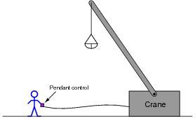
Suppose a crane has fifteen hydraulic solenoid valves controlling its motion:
- �
- Tilt up (fast)
- �
- Tilt down (fast)
- �
- Tilt up (slow)
- �
- Tilt down (slow)
- �
- Turn left (fast)
- �
- Turn right (fast)
- �
- Turn left (slow)
- �
- Turn right (slow)
- �
- Cable up (fast)
- �
- Cable down (fast)
- �
- Cable up (slow)
- �
- Cable down (slow)
- �
- Bucket open (fast)
- �
- Bucket open (slow)
- �
- Bucket close (slow)
You are part of a team building a remote "pendant" control for this crane with fifteen buttons on it for controlling each of the fifteen solenoid valves. This control pendant connects to the main system by a multiconductor cable, but you really want to limit the number of conductors in this cable to keep it as light-weight as possible:
|
|
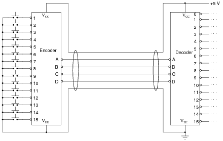
Draw a simple schematic diagram showing how a digital encoder and decoder circuit pair could be used to relay the same fifteen commands across fewer cable conductors, compared to if we used one conductor per pushbutton switch.
|
|
Follow-up question: can you think of any disadvantages to this crane control strategy, compared to using a thicker cable where each pushbutton has its own dedicated conductor?
Challenge question: my choice of active-low inputs and outputs was not arbitrary. Explain why.
Notes:
If time permits, you might want to ask students to sketch a "typical" solenoid drive sub-circuit, interposing the decoder outputs to DC (or AC!) solenoid valve coils. Several options are possible here, each with their own merits and drawbacks.
The challenge question is a good one to discuss, even if most students were not able to answer it on their own. It is not good enough to merely have a system that works - we must also have a system that is safe.
Question 17:
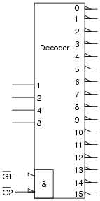
The type 74HC154 integrated circuit is a standard TTL decoder, 4-line to 16-line. Its block symbol looks like this:
|
|
What do the "wedge" symbols next to the output lines represent? Also, what purpose do the [`G1] and [`G2] inputs serve, and why is there an ampersand character (&) next to them?
Perhaps the best way to determine what the [`G1] and [`G2] inputs do is to examine the truth table given in the datasheet for this integrated circuit.
Notes:
Much may be learned from a good datasheet. This question, and others like it, prompts students to research manufacturer datasheets as a learning experience.
Note the truth table (likely) given in the datasheets your students collect. How are ïrrelevant" states denoted in the truth tables? Ask your students what this means (especially with reference to the question regarding the strobe inputs).
Question 18:
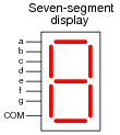
What is the purpose of a seven-segment decoder circuit? What is a ßeven-segment" display, and why do we need a decoder circuit to drive it? Research the part number for a typical seven-segment decoder circuit (either CMOS or TTL).
|
|
A special decoder circuit is needed to translate 4-bit BCD codes into the particular combinations of segment activations that represent decimal digits.
Follow-up question: what does the internal schematic of a typical seven-segment display look like? Is there just one type, or are there different types of seven-segment displays?
Notes:
Be sure to ask your students to reveal the decoder datasheets they found. Once again, manufacturer datasheets contain a wealth of information, and your students will learn much by researching them.
Question 19:
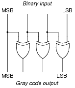
Design a circuit to convert four-bit binary to four-bit Gray code. Hint: it uses Exclusive-OR gates.
|
|
Notes:
This circuit is very easy to design, if you remember the conversion process going from binary to Gray. There are many good references available for students to learn (or re-learn) this process from, so don't simply tell them how to do it! Let them research it on their own.
Question 20:
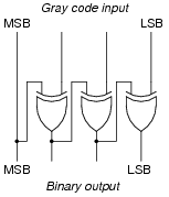
Design a circuit to convert four-bit Gray code to four-bit binary. Hint: it uses Exclusive-OR gates.
|
|
Challenge question: this circuit is not as suited to high-speed conversion as a binary-to-Gray converter, even though it uses the same quantity and same type of logic gate. Explain why problems may arise if this circuit is forced to convert Gray code inputs that are changing rapidly (for instance, translating the output of a Gray-code rotary encoder into binary, when the mechanical encoder is rotating at a very high speed).
Notes:
This circuit is very easy to design, if you remember the conversion process going from Gray to binary. There are many good references available for students to learn (or re-learn) this process from, so don't simply tell them how to do it! Let them research it on their own.
Question 21:
| Don't just sit there! Build something!! |
Learning to analyze digital circuits requires much study and practice. Typically, students practice by working through lots of sample problems and checking their answers against those provided by the textbook or the instructor. While this is good, there is a much better way.
You will learn much more by actually building and analyzing real circuits, letting your test equipment provide the änswers" instead of a book or another person. For successful circuit-building exercises, follow these steps:
- 1.
- Draw the schematic diagram for the digital circuit to be analyzed.
- 2.
- Carefully build this circuit on a breadboard or other convenient medium.
- 3.
- Check the accuracy of the circuit's construction, following each wire to each connection point, and verifying these elements one-by-one on the diagram.
- 4.
- Analyze the circuit, determining all output logic states for given input conditions.
- 5.
- Carefully measure those logic states, to verify the accuracy of your analysis.
- 6.
- If there are any errors, carefully check your circuit's construction against the diagram, then carefully re-analyze the circuit and re-measure.
Always be sure that the power supply voltage levels are within specification for the logic circuits you plan to use. If TTL, the power supply must be a 5-volt regulated supply, adjusted to a value as close to 5.0 volts DC as possible.
One way you can save time and reduce the possibility of error is to begin with a very simple circuit and incrementally add components to increase its complexity after each analysis, rather than building a whole new circuit for each practice problem. Another time-saving technique is to re-use the same components in a variety of different circuit configurations. This way, you won't have to measure any component's value more than once.
Notes:
It has been my experience that students require much practice with circuit analysis to become proficient. To this end, instructors usually provide their students with lots of practice problems to work through, and provide answers for students to check their work against. While this approach makes students proficient in circuit theory, it fails to fully educate them.
Students don't just need mathematical practice. They also need real, hands-on practice building circuits and using test equipment. So, I suggest the following alternative approach: students should build their own "practice problems" with real components, and try to predict the various logic states. This way, the digital theory "comes alive," and students gain practical proficiency they wouldn't gain merely by solving Boolean equations or simplifying Karnaugh maps.
Another reason for following this method of practice is to teach students scientific method: the process of testing a hypothesis (in this case, logic state predictions) by performing a real experiment. Students will also develop real troubleshooting skills as they occasionally make circuit construction errors.
Spend a few moments of time with your class to review some of the "rules" for building circuits before they begin. Discuss these issues with your students in the same Socratic manner you would normally discuss the worksheet questions, rather than simply telling them what they should and should not do. I never cease to be amazed at how poorly students grasp instructions when presented in a typical lecture (instructor monologue) format!
I highly recommend CMOS logic circuitry for at-home experiments, where students may not have access to a 5-volt regulated power supply. Modern CMOS circuitry is far more rugged with regard to static discharge than the first CMOS circuits, so fears of students harming these devices by not having a "proper" laboratory set up at home are largely unfounded.
A note to those instructors who may complain about the "wasted" time required to have students build real circuits instead of just mathematically analyzing theoretical circuits:
What is the purpose of students taking your course?
If your students will be working with real circuits, then they should learn on real circuits whenever possible. If your goal is to educate theoretical physicists, then stick with abstract analysis, by all means! But most of us plan for our students to do something in the real world with the education we give them. The "wasted" time spent building real circuits will pay huge dividends when it comes time for them to apply their knowledge to practical problems.
Furthermore, having students build their own practice problems teaches them how to perform primary research, thus empowering them to continue their electrical/electronics education autonomously.
In most sciences, realistic experiments are much more difficult and expensive to set up than electrical circuits. Nuclear physics, biology, geology, and chemistry professors would just love to be able to have their students apply advanced mathematics to real experiments posing no safety hazard and costing less than a textbook. They can't, but you can. Exploit the convenience inherent to your science, and get those students of yours practicing their math on lots of real circuits!