Current divider circuits
Question 1:
| Don't just sit there! Build something!! |
Learning to mathematically analyze circuits requires much study and practice. Typically, students practice by working through lots of sample problems and checking their answers against those provided by the textbook or the instructor. While this is good, there is a much better way.
You will learn much more by actually building and analyzing real circuits, letting your test equipment provide the änswers" instead of a book or another person. For successful circuit-building exercises, follow these steps:
- 1.
- Carefully measure and record all component values prior to circuit construction.
- 2.
- Draw the schematic diagram for the circuit to be analyzed.
- 3.
- Carefully build this circuit on a breadboard or other convenient medium.
- 4.
- Check the accuracy of the circuit's construction, following each wire to each connection point, and verifying these elements one-by-one on the diagram.
- 5.
- Mathematically analyze the circuit, solving for all values of voltage, current, etc.
- 6.
- Carefully measure those quantities, to verify the accuracy of your analysis.
- 7.
- If there are any substantial errors (greater than a few percent), carefully check your circuit's construction against the diagram, then carefully re-calculate the values and re-measure.
Avoid very high and very low resistor values, to avoid measurement errors caused by meter "loading". I recommend resistors between 1 kW and 100 kW, unless, of course, the purpose of the circuit is to illustrate the effects of meter loading!
One way you can save time and reduce the possibility of error is to begin with a very simple circuit and incrementally add components to increase its complexity after each analysis, rather than building a whole new circuit for each practice problem. Another time-saving technique is to re-use the same components in a variety of different circuit configurations. This way, you won't have to measure any component's value more than once.
Notes:
It has been my experience that students require much practice with circuit analysis to become proficient. To this end, instructors usually provide their students with lots of practice problems to work through, and provide answers for students to check their work against. While this approach makes students proficient in circuit theory, it fails to fully educate them.
Students don't just need mathematical practice. They also need real, hands-on practice building circuits and using test equipment. So, I suggest the following alternative approach: students should build their own "practice problems" with real components, and try to mathematically predict the various voltage and current values. This way, the mathematical theory "comes alive," and students gain practical proficiency they wouldn't gain merely by solving equations.
Another reason for following this method of practice is to teach students scientific method: the process of testing a hypothesis (in this case, mathematical predictions) by performing a real experiment. Students will also develop real troubleshooting skills as they occasionally make circuit construction errors.
Spend a few moments of time with your class to review some of the "rules" for building circuits before they begin. Discuss these issues with your students in the same Socratic manner you would normally discuss the worksheet questions, rather than simply telling them what they should and should not do. I never cease to be amazed at how poorly students grasp instructions when presented in a typical lecture (instructor monologue) format!
A note to those instructors who may complain about the "wasted" time required to have students build real circuits instead of just mathematically analyzing theoretical circuits:
What is the purpose of students taking your course?
If your students will be working with real circuits, then they should learn on real circuits whenever possible. If your goal is to educate theoretical physicists, then stick with abstract analysis, by all means! But most of us plan for our students to do something in the real world with the education we give them. The "wasted" time spent building real circuits will pay huge dividends when it comes time for them to apply their knowledge to practical problems.
Furthermore, having students build their own practice problems teaches them how to perform primary research, thus empowering them to continue their electrical/electronics education autonomously.
In most sciences, realistic experiments are much more difficult and expensive to set up than electrical circuits. Nuclear physics, biology, geology, and chemistry professors would just love to be able to have their students apply advanced mathematics to real experiments posing no safety hazard and costing less than a textbook. They can't, but you can. Exploit the convenience inherent to your science, and get those students of yours practicing their math on lots of real circuits!
Question 2:
We know that the voltage in a parallel circuit may be calculated with this formula:
|
We also know that the current through any single resistor in a parallel circuit may be calculated with this formula:
|
Combine these two formulae into one, in such a way that the E variable is eliminated, leaving only IR expressed in terms of Itotal, Rtotal, and R.
|
How is this formula similar, and how is it different, from the "voltage divider" formula?
Notes:
Though this "current divider formula" may be found in any number of electronics reference books, your students need to understand how to algebraically manipulate the given formulae to arrive at this one.
At first it may seem as though the two divider formulae (voltage versus current) are easy to confuse. Is it [R/(Rtotal)] or [(Rtotal)/R]? However, there is a very simple way to remember which fraction belongs with which formula, based on the numerical value of that fraction. Mention this to your students and at least one of them will be sure to recognize the pattern.
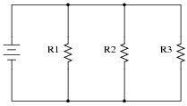
Question 3:
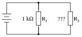
What will happen to the current through R1 and R2 if resistor R3 fails open?
|
|
Notes:
A very common mistake of beginning electronics students is to think that a failed resistor in a parallel circuit supplied by a voltage source causes current through the other resistors to change. A simple verification using Ohm's Law will prove otherwise, though.
If this mistake is revealed during discussion, ask the class this very important question: "What assumption has to be made in order to conclude that the other two currents will change?" Invariably, the assumption is that the source outputs a constant current rather than a constant voltage.
Another common mistake of beginning electronics students is to think that the position of the failed resistor matters. Ask your students to determine what will happen to the current through R2 and R3 if R1 were to fail open instead. If there are any misunderstandings, use the discussion time to correct them and improve everyone's comprehension of the concept.
Question 4:
Determine the amount of current conducted by each resistor in this circuit, if each resistor has a color code of Org, Org, Red, Gld (assume perfectly precise resistance values - 0% error):

|
|
Also, determine the following information about this circuit:
- �
- Voltage across each resistor
- �
- Power dissipated by each resistor
- �
- Ratio of each resistor's current to battery current ([(IR)/(Ibat)])
- �
- Ratio of total circuit resistance to each resistor's resistance ([(Rtotal)/R])
Voltage across each resistor = 11 V
Power dissipated by each resistor = 36.67 mW
Current ratio = [1/3]
Resistance ratio = [1/3]
Notes:
When performing the mathematical analysis on this circuit, there is more than one possible sequence of steps to obtaining the solutions. Different students in your class may very well have different solution sequences, and it is a good thing to have students share their differing problem-solving techniques before the whole class.
An important aspect of this question is for students to observe the identical ratios (current versus resistance), and determine whether or not these ratios are equal by chance or equal by necessity. Ask your students, "What kind of evidence would prove these ratios were merely equal by chance?" Setting mathematics aside and viewing this circuit from a purely experimental point of view, ask your students what data could possibly prove these ratios to be equal by chance in this particular case? Hint: it would only take a single example to prove this!
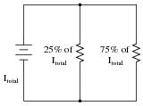
Question 5:
Calculate the necessary resistor values to produce the following percentage splits in current:
|
|
Hint: one resistor carries three times the current of the other.
Notes:
Different students will likely arrive at different solutions for this design task. Have your students share their differing solutions, emphasizing that there is often more than one acceptable solution to a problem!
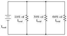
Question 6:
Calculate one possible set of resistor values that would produce the following percentage splits in current:
|
|
Notes:
Different students will likely arrive at different solutions for this design task. Have your students share their differing solutions, emphasizing that there is often more than one acceptable solution to a problem!
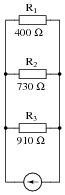
Question 7:
Calculate the percentage of total current for each resistor in this parallel circuit:
|
|
R2 = 27.6% of total current
R3 = 22.1% of total current
Notes:
Nothing to comment on here, really. Just a straight-forward current divider formula problem!
Question 8:
Calculate the proper value of resistance R2 needs to be in order to draw 40% of the total current in this circuit:
|
|
Follow-up question: explain how you could arrive at a rough estimate of R2's necessary value without doing any algebra. In other words, show how you could at least set limits on R2's value (i.e. "We know it has to be less than . . ." or "We know it has to be greater than . . .").
Notes:
This is an interesting problem to solve algebraically from the current divider formula. I recommend using the product-over-sum formula for parallel resistance if you plan on doing this algebraically. The estimation question (in the follow-up) is also very good to discuss with your students. It is possible to at least "bracket" the value of R2 between two different resistance values without doing any math more complex than simple (fractional) arithmetic.
Of course, a less refined approach to solving this problem would be to assume a certain battery voltage and work with numerical figures - but what fun is that?
Question 9:
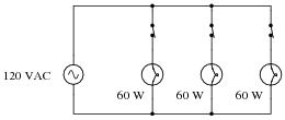
A student is trying to use the "current divider formula" to calculate current through the second light bulb in a three-lamp lighting circuit (typical for an American household):
|
|
The student uses Joule's Law to calculate the resistance of each lamp (240 W), and uses the parallel resistance formula to calculate the circuit's total resistance (80 W). With the latter figure, the student also calculates the circuit's total (source) current: 1.5 A.
Plugging this into the current divider formula, the current through any one lamp turns out to be:
|
This value of 0.5 amps per light bulb correlates with the value obtained from Joule's Law directly for each lamp: 0.5 amps from the given values of 120 volts and 60 watts.
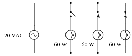
The trouble is, something doesn't add up when the student re-calculates for a scenario where one of the switches is open:
|
|
With only two light bulbs in operation, the student knows the total resistance must be different than before: 120 W instead of 80 W. However, when the student plugs these figures into the current divider formula, the result seems to conflict with what Joule's Law predicts for each lamp's current draw:
|
At 0.75 amps per light bulb, the wattage is no longer 60 W. According to Joule's Law, it will now be 90 watts (120 volts at 0.75 amps). What is wrong here? Where did the student make a mistake?
Notes:
I am surprised how often this principle is misunderstood by students as they first learn about parallel circuits. It seems natural for many of them to assume that total circuit current is a constant when the source is actually a constant-voltage source!
Question 10:
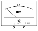
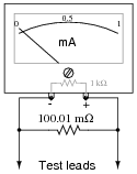
Suppose an ammeter has a range of 0 to 1 milliamp, and an internal resistance of 1000 W:
|
|
Show how a single resistor could be connected to this ammeter to extend its range to 0 to 10 amps. Calculate the resistance of this "range" resistor, as well as its necessary power dissipation rating.
|
|
A power dissipation rating of at least 10 watts is necessary for this application.
Notes:
Ammeter ranging is a very practical example of current divider circuitry.