Inductance
Question 1:
|
One of the fundamental principles of calculus is a process called integration. This principle is important to understand because it is manifested in the behavior of inductance. Thankfully, there are more familiar physical systems which also manifest the process of integration, making it easier to comprehend.
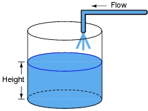
If we introduce a constant flow of water into a cylindrical tank with water, the water level inside that tank will rise at a constant rate over time:
|
|
In calculus terms, we would say that the tank integrates water flow into water height. That is, one quantity (flow) dictates the rate-of-change over time of another quantity (height).
Like the water tank, electrical inductance also exhibits the phenomenon of integration with respect to time. Which electrical quantity (voltage or current) dictates the rate-of-change over time of which other quantity (voltage or current) in an inductance? Or, to re-phrase the question, which quantity (voltage or current), when maintained at a constant value, results in which other quantity (current or voltage) steadily ramping either up or down over time?
Challenge question: can you think of a way we could exploit the similarity of inductive voltage/current integration to simulate the behavior of a water tank's filling, or any other physical process described by the same mathematical relationship?
Notes:
The concept of integration doesn't have to be overwhelmingly complex. Electrical phenomena such as capacitance and inductance may serve as excellent contexts in which students may explore and comprehend the abstract principles of calculus. The amount of time you choose to devote to a discussion of this question will depend on how mathematically adept your students are.
Question 2:
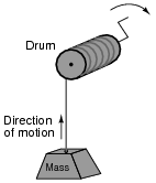
Suppose a mass is connected to a winch by means of a cable, and a person turns the winch drum to raise the mass off the ground:
|
|
A physicist would likely look at this scenario as an example of energy exchange: the person turning the drum is expending energy, which in turn is being stored in the mass in potential form.
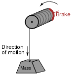
Suppose now that the person stops turning the drum and instead engages a brake mechanism on the drum so that it reverses rotation and slowly allows the mass to return to ground level. Once again, a physicist would view this scenario as an exchange of energy: the mass is now releasing energy, while the brake mechanism is converting that released energy into heat:
|
|
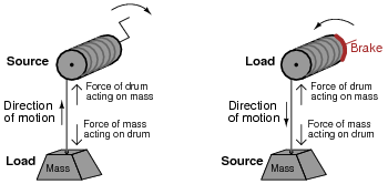
In each of the above scenarios, draw arrows depicting directions of two forces: the force that the mass exerts on the drum, and the force that the drum exerts on the mass. Compare these force directions with the direction of motion in each scenario, and explain how these directions relate to the mass and drum alternately acting as energy source and energy load.
|
|
Follow-up question: although it may not be obvious, this question closely relates to the exchange of energy between components in electrical circuits! Explain this analogy.
Notes:
Students typically find the concept of energy flow confusing with regard to electrical components. I try to make this concept clearer by using mechanical analogies, in which force and motion act as analog quantities to voltage and current (or visa-versa).
Question 3:
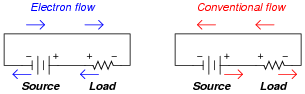
Draw the direction of current in this circuit, and also identify the polarity of the voltage across the battery and across the resistor. Then, compare the battery's polarity with the direction of current through it, and the resistor's polarity with the direction of current through it.
|
|
What do you notice about the relationship between voltage polarity and current direction for these two different types of components? Identify the fundamental distinction between these two components that causes them to behave differently.
|
|
Whichever notation you choose to follow in your analysis of circuits, the understanding should be the same: the reason voltage polarities across the resistor and battery differ despite the same direction of current through both is the flow of power. The battery acts as a source, while the resistor acts as a load.
Notes:
This type of distinction is very important in the study of physics as well, where one must determine whether a mechanical system is doing work or whether work is being done on it. A clear understanding of the relationship between voltage polarity and current direction for sources and loads is very important for students to have before they study reactive devices such as inductors and capacitors!
Question 4:
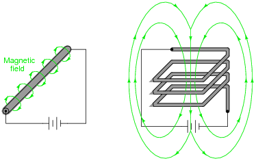
Draw the pattern of the magnetic field produced by electric current through a straight wire and through a wire coil:

|
|
Explain your answer using either the right-hand rule (conventional flow) or the left-hand rule (electron flow).
|
|
Notes:
In your students' research, they will encounter a "right-hand rule" as well as a "left-hand rule" for relating electric current with magnetic field directions. The distinction between the two rules depends on whether the text uses "conventional flow" notation or ëlectron flow" notation to denote the movement of electrical charge through the conductors. Sadly, this is another one of those concepts in electricity that has been made unnecessarily confusing by the prevalence of two ßtandard" notions for electric current.
Question 5:
As an electric current is passed through a coil of wire, it creates a magnetic field. If the magnitude of this current changes over time, so will the strength of the magnetic field.
We also know that a magnetic field flux that changes over time will induce a voltage along the length of a wire coil. Explain how the complementary principles of electromagnetism and electromagnetic induction manifest themselves simultaneously in the same wire coil to produce self-induction.
Also, explain how Lenz's Law relates to the polarity of the coil's self-induced voltage.
Notes:
Self-induction is not a difficult concept to grasp if one already possesses a good understanding of electromagnetism, electromagnetic induction, and Lenz's Law. Some students may struggle understanding self-induction, because it is probably the first application they've seen where these three phenomena inter-relate simultaneously.
Question 6:
|
�f(x) dx Calculus alert! |
|
|
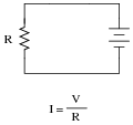
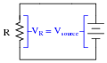
Although an analysis of this circuit probably seems trivial to you, I would like to encourage you to look at what is happening here from a fresh perspective. An important principle observed many times in the study of physics is that of equilibrium, where quantities naturally ßeek" a state of balance. The balance sought by this simple circuit is equality of voltage: the voltage across the resistor must settle at the same value as the voltage output by the source:
|
|
If the resistor is viewed as a source of voltage seeking equilibrium with the voltage source, then current must converge at whatever value necessary to generate the necessary balancing voltage across the resistor, according to Ohm's Law (V = IR). In other words, the resistor's current achieves whatever magnitude it has to in order to generate a voltage drop equal to the voltage of the source.
This may seem like a strange way of analyzing such a simple circuit, with the resistor ßeeking" to generate a voltage drop equal to the source, and current "magically" assuming whatever value it must to achieve that voltage equilibrium, but it is helpful in understanding other types of circuit elements.
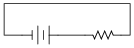
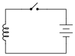
For example, here we have a source of DC voltage connected to a large coil of wire through a switch. Assume that the wire coil has negligible resistance (0 W):
|
|
Like the resistor circuit, the coil will ßeek" to achieve voltage equilibrium with the voltage source once the switch is closed. However, we know that the voltage induced in a coil is not directly proportional to current as it is with a resistor - instead, a coil's voltage drop is proportional to the rate of change of magnetic flux over time as described by Faraday's Law of electromagnetic induction:
|
Where,
vcoil = Instantaneous induced voltage, in volts
N = Number of turns in wire coil
[(d f)/dt] = Instantaneous rate of change of magnetic flux, in webers per second
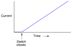
Assuming a linear relationship between coil current and magnetic flux (i.e. f doubles when i doubles), describe this simple circuit's current over time after the switch closes.
|
|
Challenge question: real wire coils contain electrical resistance (unless they're made of superconducting wire, of course), and we know how voltage equilibrium occurs in resistive circuits: the current converges at a value necessary for the resistance to drop an equal amount of voltage as the source. Describe, then, what the current does in a circuit with a real wire coil, not a superconducting wire coil.
Notes:
Students who do not yet understand the concept of inductance may be inclined to suggest that the current in this circuit will be infinite, following Ohm's Law (I = E/R). One of the purposes of this question is to reveal such misunderstandings, so that they may be corrected.
This circuit provides an excellent example of the calculus principle integration, where the application of a steady voltage across the inductor results in a steadily increasing current. Whether or not you should touch on this subject depends on the mathematical aptitude of your students.
Question 7:
Inductance is a very important property in many types of electric circuits. Define what ïnductance" is, and what causes it.
Inductance is caused by the establishment of a magnetic field around a conductor.
Notes:
Ask students what unit of measurement inductance is expressed in. Also, ask them if they think the inductance of any given conductor changes with the applied current or stored energy, or if inductance is a quantity independent of particular electrical conditions.
Question 8:
|
If the number of turns of wire in an electromagnet coil is tripled, what happens to the magnitude of the magnetic flux (F) generated by it, assuming that none of the other variables change (current through the coil, reluctance of magnetic circuit, etc.)?
If the number of turns of wire in an inductor is tripled, what happens to the magnitude of the induced voltage for a given rate of magnetic flux change over time ([(df)/dt])?
If the number of turns of wire in an inductor is tripled, what happens to the magnitude of its inductance, measured in Henrys? Explain your answer.
If [(df)/dt] triples, then e triples, all other factors being equal.
If N triples, then L increases by a factor of nine, all other factors being equal.
Notes:
This question presents an interesting problem in qualitative mathematics. It is closely related to the "chain rule" in calculus, where one function y = f(x) is embedded within another function z = f(y), such that [dz/dy][dy/dx] = [dz/dx]. The purpose of this exercise is for students to gain a conceptual grasp of why inductance does not vary linearly with changes in N.
Of course, students can obtain the same (third) answer just by looking at the inductance formula (in terms of N, m, A, and l), without all the conceptual work. It would be good, in fact, if a student happens to derive the same answer by inspection of this formula, just to add variety to the discussion. But the real purpose of this question, again, is a conceptual understanding of that formula.
Question 9:
The amount of inductance inherent in a wire coil may be calculated by the following equation:
|
Where,
L = Inductance in Henrys
N = Number of wire "turns" wrapped around the core
m = Permeability of core material (absolute, not relative)
A = Core area, in square meters
l = Length of core, in meters
Calculate how many turns of wire must be wrapped around a hollow, non-magnetic (air) core 2 cm in diameter and 10 cm in length in order to create an inductance of 22 mH. You may use the permeability of free space (m0) for the m value of the air core.
Next, calculate the required number of turns to produce the same inductance with a solid iron core of the same dimensions, assuming that the iron has a relative permeability (mr) of 4000.
Finally, knowing that the formula for the area of a circle is pr2, re-write the inductance equation so as to accept a value for inductor radius rather than inductor area. In other words, substitute radius (r) for area (A) in this equation in such a way that it still provides an accurate figure for inductance.
New inductance equation:
|
Notes:
This problem is first and foremost an algebraic manipulation exercise: solving for N given the values of the other variables. Students should be able to research the value of m0 quite easily, being a well-defined physical constant.
Note that in this equation, the Greek letter "mu" (m) is not a metric prefix, but rather an actual variable! This confuses many students, who are used to interpreting m as the metric prefix "micro" ([1/1,000,000]).
Note also how the re-written equation puts pi (p) ahead of all the variables in the numerator of the fraction. This is not absolutely necessary, but it is conventional to write constants before variables. Do not be surprised if some students ask about this, as their answers probably looked like this:
|
Question 10:
Suppose you wished to build a component with no other purpose than to provide inductance in an electric circuit (an inductor). How might you design such a device to perform this function, and how could you maximize its inductance?
To increase inductance:
- �
- Increase number of "turns" in coil
- �
- Increase diameter of coil
- �
- Decrease length of coil
- �
- Increase permeability of core material
Notes:
These factors are important to understand for comprehending the function of variable inductors. Be sure to bring up the subject of variable inductors in your discussion with students.
Question 11:
Magnetic fields, like all fields, have two fundamental measures: field force and field flux. In an inductor, which of these field quantities is directly related to current through the wire coil, and which is directly related to the amount of energy stored?
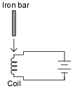
Based on this relationship, which magnetic field quantity changes when a bar of iron is brought closer to a wire coil, connected to a source of constant current?
|
|
If an iron bar is brought closer to a wire coil connected to a constant current source, the magnetic field force generated by the coil will remain unchanged, while the magnetic field flux will increase (and along with it, the amount of energy stored in the magnetic field).
Notes:
The concept of a field is quite abstract, but at least magnetic fields are something within most peoples' realm of experience. This question is good for helping students distinguish between field force and field flux, in terms they should understand (constant current through a coil, versus the attractive force produced by a magnetic field flux).
Question 12:
Suppose an inductor is connected directly to an adjustable-current source, and the current of that source is steadily increased over time. We know that an increasing current through an inductor will produce a magnetic field of increasing strength. Does this increase in magnetic field constitute an accumulation of energy in the inductor, or a release of energy from the inductor? In this scenario, does the inductor act as a load or as a source of electrical energy?
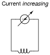
|
|
Now, suppose the adjustable current source is steadily decreased over time. We know this will result in a magnetic field of decreasing strength in the inductor. Does this decrease in magnetic field constitute an accumulation of energy in the inductor, or a release of energy from the inductor? In this scenario, does the inductor act as a load or as a source of electrical energy?
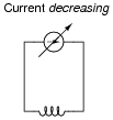
|
|
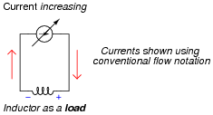
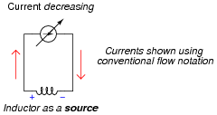
For each of these scenarios, label the inductor's voltage drop polarity.
|
|
As the applied current decreases, the inductor acts as a source, releasing accumulated energy to the rest of the circuit, as though it were a current source itself of superior current. Acting as a source, the voltage dropped by the inductor will be in the same polarity as across a battery, powering a load.
|
|
Notes:
Relating the polarity of voltage across an inductor to a change of applied current over time is a complex concept for many students. Since it involves rates of change over time, it is an excellent opportunity to introduce calculus concepts ([d/dt]).
Vitally important to students' conceptual understanding of an inductor exposed to increasing or decreasing currents is the distinction between an electrical energy source versus a load. Students need to think "battery" and "resistor," respectively when determining the relationship between direction of current and voltage drop. The complicated aspect of inductors (and capacitors!) is that they may switch character in an instant, from being a source of energy to being a load, and visa-versa. The relationship is not fixed as it is for resistors, which are always energy loads.
Question 13:
|
Ohm's Law tells us that the amount of voltage dropped by a fixed resistance may be calculated as such:
|
However, the relationship between voltage and current for a fixed inductance is quite different. The Öhm's Law" formula for an inductor is as such:
|
What significance is there in the use of lower-case variables for current (i) and voltage (e)? Also, what does the expression [di/dt] mean? Note: in case you think that the d's are variables, and should cancel out in this fraction, think again: this is no ordinary quotient! The d letters represent a calculus concept known as a differential, and a quotient of two d terms is called a derivative.
Follow-up question: manipulate this equation to solve for the other two variables ([di/dt] = � ; L = �).
Notes:
I have found that the topics of capacitance and inductance are excellent contexts in which to introduce fundamental principles of calculus to students. The time you spend discussing this question and questions like it will vary according to your students' mathematical abilities.
Even if your students are not ready to explore calculus, it is still a good idea to discuss how the relationship between current and voltage for an inductance involves time. This is a radical departure from the time-independent nature of resistors, and of Ohm's Law!
Question 14:
Complete this statement by substituting the correct electrical variables (voltage, current, resistance, inductance):
- Inductors oppose changes in (fill-in-the-blank), reacting to such changes by producing a (fill-in-the-blank).
Notes:
Emphasize to your students that inductance is an essentially reactive property, opposing change in current over time. It is not steady current that inductors react to, only changing current.
Question 15:
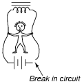
Many years ago, I decided to experiment with electromagnetism by making an electromagnet out of a spool of wire. I placed a steel bolt through the center of the spool so as to have a core of high permeability, and passed current from a battery through the wire to make a magnetic field. Not having any "jumper" wires, I held the wire ends of the spool in contact with the 9-volt battery terminals, one in each hand.
The electromagnet worked just fine, and I was able to move some steel paperclips with the magnetic field generated by it. However, when I broke the circuit by releasing one of the wire ends from the battery terminal it was touching, I received a small electric shock! Shown here is a schematic diagram of me, in the circuit:
|
|
At the time, I didn't understand how inductance worked. I only understood how to make magnetism with electricity, but I didn't realize a coil of wire could generate (high voltage!) electricity from its own magnetic field. I did know, however, that the 9 volts output by the battery was much too weak to shock me (yes, I touched the battery terminals directly to verify this fact), so something in the circuit must have generated a voltage greater than 9 volts.
If you had been there to explain what just happened to me, what would you say?
Notes:
One way to help understand how an inductor could produce such large voltages is to consider it as a temporary current source, which will output as much voltage as necessary in an effort to maintain constant current. Just as ideal current sources are dangerous to open-circuit, current-carrying inductors are likewise capable of generating tremendous transient voltages.
Although there was no real safety hazard with my experiment, there potentially could have been, provided different circumstances. Discuss with your students what would have been necessary to create an actual safety hazard.
Question 16:
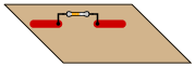
Components soldered into printed circuit boards often possess ßtray" inductance, also known as parasitic inductance. Observe this resistor, soldered in to a circuit board:
|
|
Where does the parasitic inductance come from? What is it about a resistor, mounted to a circuit board, that creates a (very) small amount of inductance? How is it possible to minimize this inductance, in case it is detrimental to the circuit's operation?
Notes:
In high-frequency AC circuits, such as computer circuits where pulses of voltage oscillate at millions of cycles per second, even short lengths of wire or traces on a circuit board may present substantial trouble by virtue of their stray inductance. Some of this parasitic inductance may be reduced by proper circuit board assembly, some of it by a re-design of component layout on the circuit board.
According to an article in IEEE Spectrum magazine ("Putting Passives In Their Place", July 2003, Volume 40, Number 7, page 29), the transient currents created by fast-switching logic circuits can be as high as 500 amps/ns, which is a [di/dt] rate of 500 billion amps per second!! At these levels, even a few picohenrys of parasitic inductance along component leads and circuit board traces will result in significant voltage drops.
Question 17:
Many precision resistors utilize a wire-wound construction, where the resistance is determined by the type and length of wire wrapped around a spool. This form of construction allows for high precision of resistance, with low temperature sensitivity if certain metal alloys are used for the wire.
Unfortunately, though, wrapping wire around a spool forms a coil, which will naturally possess a significant amount of inductance. This is generally undesirable, as we would like to have resistors possessing only resistance, with no "parasitic" properties.
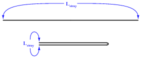
There is, however, a special way in which a wire coil may be wound so as to have almost no inductance. This method is called bifilar winding, and it is common in wire-wound resistor construction. Describe how bifilar winding works, and why it eliminates parasitic inductance.
|
|
Now, how could a non-inductive coil of wire be made using the same principle?
Notes:
This technique is very useful in reducing or eliminating parasitic inductance. Typically, parasitic inductance is not a problem unless very high rates of current change are involved, such as in high-frequency AC circuits (radio, high-speed digital logic, etc.). In such applications, knowing how to control stray inductance is very important to proper circuit operation.
Question 18:
|
Digital logic circuits, which comprise the inner workings of computers, are essentially nothing more than arrays of switches made from semiconductor components called transistors. As switches, these circuits have but two states: on and off, which represent the binary states of 1 and 0, respectively.
The faster these switch circuits are able to change state, the faster the computer can perform arithmetic and do all the other tasks computers do. To this end, computer engineers keep pushing the limits of transistor circuit design to achieve faster and faster switching rates.
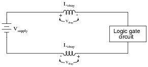
This race for speed causes problems for the power supply circuitry of computers, though, because of the current ßurges" (technically called transients) created in the conductors carrying power from the supply to the logic circuits. The faster these logic circuits change state, the greater the [di/dt] rates-of-change exist in the conductors carrying current to power them. Significant voltage drops can occur along the length of these conductors due to their parasitic inductance:
|
|
Suppose a logic gate circuit creates transient currents of 175 amps per nanosecond (175 A/ns) when switching from the öff" state to the ön" state. If the total inductance of the power supply conductors is 10 picohenrys (9.5 pH), and the power supply voltage is 5 volts DC, how much voltage remains at the power terminals of the logic gate during one of these ßurges"?
Notes:
Students will likely marvel at the [di/dt] rate of 175 amps per nanosecond, which equates to 175 billion amps per second. Not only is this figure realistic, though, it is also low by some estimates (see IEEE Spectrum magazine, July 2003, Volume 40, Number 7, in the article "Putting Passives In Their Place"). Some of your students may be very skeptical of this figure, not willing to believe that ä computer power supply is capable of outputting 175 billion amps?!"
This last statement represents a very common error students commit, and it is based on a fundamental misunderstanding of [di/dt]. "175 billion amps per second" is not the same thing as "175 billion amps". The latter is an absolute measure, while the former is a rate of change over time. It is the difference between saying "1500 miles per hour" and "1500 miles". Just because a bullet travels at 1500 miles per hour does not mean it will travel 1500 miles! And just because a power supply is incapable of outputting 175 billion amps does not mean it cannot output a current that changes at a rate of 175 billion amps per second!
Question 19:
Electrical inductance has a close mechanical analogy: inertia. Explain what mechanical ïnertia" is, and how the quantities of velocity and force applied to an object with mass are respectively analogous to current and voltage applied to an inductance.
|
Where,
F = Net force applied to object
m = Mass of object
v = Velocity of object
t = Time
In a similar manner, a pure inductance experiencing a constant voltage will exhibit a constant rate of current change over time:
|
Notes:
Explain to your students how the similarities between inertia and inductance are so close, that inductors can be used to electrically model mechanical inertia.
Question 20:
|
Inductors store energy in the form of a magnetic field. We may calculate the energy stored in an inductance by integrating the product of inductor voltage and inductor current (P = IV) over time, since we know that power is the rate at which work (W) is done, and the amount of work done to an inductor taking it from zero current to some non-zero amount of current constitutes energy stored (U):
|
|
|
Find a way to substitute inductance (L) and current (I) into the integrand so you may integrate to find an equation describing the amount of energy stored in an inductor for any given inductance and current values.
|
Notes:
The integration required to obtain the answer is commonly found in calculus-based physics textbooks, and is an easy (power rule) integration.