Passive integrator and differentiator circuits
Question 1:
|
Calculus is a branch of mathematics that originated with scientific questions concerning rates of change. The easiest rates of change for most people to understand are those dealing with time. For example, a student watching their savings account dwindle over time as they pay for tuition and other expenses is very concerned with rates of change (dollars per year being spent).
In calculus, we have a special word to describe rates of change: derivative. One of the notations used to express a derivative (rate of change) appears as a fraction. For example, if the variable S represents the amount of money in the student's savings account and t represents time, the rate of change of dollars over time would be written like this:
|
The following set of figures puts actual numbers to this hypothetical scenario:
- �
- Date: November 20
- �
- Saving account balance (S) = $12,527.33
- �
- Rate of spending ([dS/dt]) = -5,749.01 per year
List some of the equations you have seen in your study of electronics containing derivatives, and explain how rate of change relates to the real-life phenomena described by those equations.
|
Voltage and current for an inductor:
|
Electromagnetic induction:
|
I leave it to you to describe how the rate-of-change over time of one variable relates to the other variables in each of the scenarios described by these equations.
Follow-up question: why is the derivative quantity in the student's savings account example expressed as a negative number? What would a positive [dS/dt] represent in real life?
Challenge question: describe actual circuits you could build to demonstrate each of these equations, so that others could see what it means for one variable's rate-of-change over time to affect another variable.
Notes:
The purpose of this question is to introduce the concept of the derivative to students in ways that are familiar to them. Hopefully the opening scenario of a dwindling savings account is something they can relate to!
A very important aspect of this question is the discussion it will engender between you and your students regarding the relationship between rates of change in the three equations given in the answer. It is very important to your students' comprehension of this concept to be able to verbally describe how the derivative works in each of these formulae. You may want to have them phrase their responses in realistic terms, as if they were describing how to set up an illustrative experiment for a classroom demonstration.
Question 2:
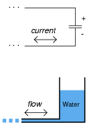
How does the rate of charge flow (current) into and out of a capacitor relate to the amount of voltage across its terminals? How does the rate of water flow into and out of a vessel relate to the amount of water stored in that vessel?
|
|
Notes:
The existence of such an appropriate analogy for capacitor action makes an explanation unnecessary, even if the concept takes a bit of thought to comprehend at first. It is important that students clearly distinguish the quantities of current, voltage, and charge in a capacitor circuit just as they clearly distinguish the quantities of liquid height, flow rate, and liquid volume in a hydraulic system.
Question 3:
|
�f(x) dx Calculus alert! |
|
Another way of saying this is to state that the capacitors differentiate voltage with respect to time, and express this time-derivative of voltage as a current.
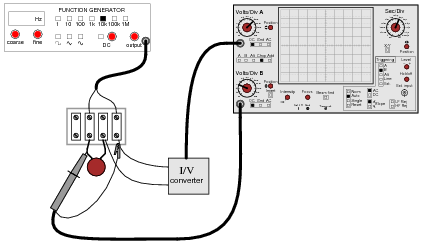
Suppose we had an oscilloscope capable of directly measuring current, or at least a current-to-voltage converter that we could attach to one of the probe inputs to allow direct measurement of current on one channel. With such an instrument set-up, we could directly plot capacitor voltage and capacitor current together on the same display:
|
|
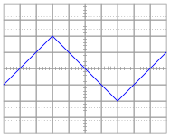
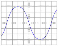
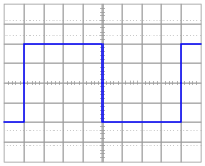
For each of the following voltage waveforms (channel B), plot the corresponding capacitor current waveform (channel A) as it would appear on the oscilloscope screen:
|
|
|
|

|
|
Note: the amplitude of your current plots is arbitrary. What I'm interested in here is the shape of each current waveform!
|
|
|
|
|
|
Follow-up question: what electronic device could perform the function of a "current-to-voltage converter" so we could use an oscilloscope to measure capacitor current? Be as specific as you can in your answer.
Notes:
Here, I ask students to relate the instantaneous rate-of-change of the voltage waveform to the instantaneous amplitude of the current waveform. Just a conceptual exercise in derivatives.
Question 4:
|
�f(x) dx Calculus alert! |
|
Another way of saying this is to state that the capacitors differentiate voltage with respect to time, and express this time-derivative of voltage as a current.
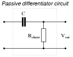
We may build a simple circuit to produce an output voltage proportional to the current through a capacitor, like this:
|
|
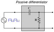
The resistor is called a shunt because it is designed to produce a voltage proportional to current, for the purpose of a parallel (ßhunt")-connected voltmeter or oscilloscope to measure that current. Ideally, the shunt resistor is there only to help us measure current, and not to impede current through the capacitor. In other words, its value in ohms should be very small compared to the reactance of the capacitor (Rshunt << XC).
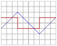
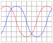
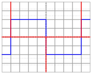
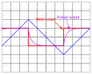
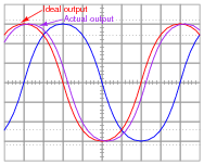
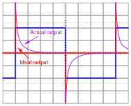
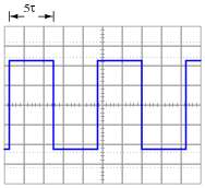
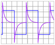
Suppose that we connect AC voltage sources with the following wave-shapes to the input of this passive differentiator circuit. Sketch the ideal (time-derivative) output waveform shape on each oscilloscope screen, as well as the shape of the actual circuit's output voltage (which will be non-ideal, of course):

|
|

|
|
|
|
Note: the amplitude of your plots is arbitrary. What I'm interested in here is the shape of the ideal and actual output voltage waveforms!
Hint: I strongly recommend building this circuit and testing it with triangle, sine, and square-wave input voltage signals to obtain the corresponding actual output voltage wave-shapes!
|
|
|
|
|
|
Follow-up question: given that Rshunt << XC in order that the resistance does not impede the capacitor current to any significant extent, what does this suggest about the necessary time-constant (t) of a passive differentiator circuit? In other words, what values of R and C would work best in such a circuit to produce an output waveform that is as close to ideal as possible?
Notes:
This question really is best answered by experimentation. I recommend having a signal generator and oscilloscope on-hand in the classroom to demonstrate the operation of this passive differentiator circuit. Challenge students with setting up the equipment and operating it!
Question 5:
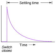
Generally speaking, how many "time constants" worth of time does it take for the voltage and current to ßettle" into their final values in an RC or LR circuit, from the time the switch is closed?
|
|
However, after 5 time constants' worth of time, the variables in an RC or LR circuit will have settled to within 0.6% of their final values, which is good enough for most people to call "final."
Notes:
The stock answer of "5 time constants" as the amount of time elapsed between the transient event and the "final" settling of voltage and current values is widespread, but largely misunderstood. I've encountered more than a few graduates of electronics programs who actually believe there is something special about the number 5, as though everything grinds to a halt at exactly 5 time constants worth of time after the switch closes.
In reality, the rule of thumb of "5 time constants" as a settling time in RC and LR circuits is an approximation only. Somewhere I recall reading an old textbook that specified ten time constants as the time required for all the variables to reach their final values. Another old book declared seven time constants. I think we're getting impatient as the years roll on!
Question 6:
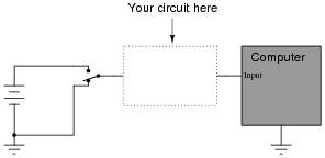
Suppose a fellow electronics technician approaches you with a design problem. He needs a simple circuit that outputs brief pulses of voltage every time a switch is actuated, so that a computer receives a single pulse signal every time the switch is actuated, rather than a continuous ön" signal for as long as the switch is actuated:
|
|
The technician suggests you build a passive differentiator circuit for his application. You have never heard of this circuit before, but you probably know where you can research to find out what it is! He tells you it is perfectly okay if the circuit generates negative voltage pulses when the switch is de-actuated: all he cares about is a single positive voltage pulse to the computer each time the switch actuates. Also, the pulse needs to be very short: no longer than 2 milliseconds in duration.
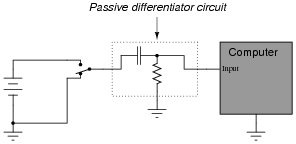
Given this information, draw a schematic diagram for a practical passive differentiator circuit within the dotted lines, complete with component values.
|
|
Did you really think I would give you the component values, too? I can't make it too easy for you!
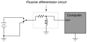
Challenge question: An alternative design to the differentiator circuit shown above is this:
|
|
This circuit would certainly work to create brief pulses of voltage to the computer input, but it would also likely destroy the computer's input circuitry after a few switch actuations! Explain why.
Notes:
The behavior of a differentiator circuit may be confusing to students with exposure to calculus, because the output of such a circuit is not strictly related to the rate of change of the input voltage over time. However, if the time constant of the circuit is short in comparison to the period of the input signal, the result is close enough for many applications.
Question 7:
Plot the output waveform of a passive differentiator circuit, assuming the input is a symmetrical square wave and the circuit's RC time constant is about one-fifth of the square wave's pulse width:
|
|
|
|
|
|
Follow-up question #1: what would we have to change in this passive differentiator circuit to make the output more closely resemble ideal differentiation?
Follow-up question #2: explain how it is possible that the differentiator's output waveform has a greater peak amplitude than the input (square) waveform.
Notes:
Ask students to contrast the behavior of this passive differentiator circuit against that of a perfect differentiator (with t = 0). What should the derivative plot of a square wave look like?
Question 8:
|
�f(x) dx Calculus alert! |
|
|
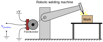
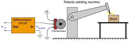
As the robotic arm rotates up and down, the potentiometer wire moves along the resistive strip inside, producing a voltage directly proportional to the arm's position. A voltmeter connected between the potentiometer wiper and ground will then indicate arm position. A computer with an analog input port connected to the same points will be able to measure, record, and (if also connected to the arm's motor drive circuits) control the arm's position.
If we connect the potentiometer's output to a differentiator circuit, we will obtain another signal representing something else about the robotic arm's action. What physical variable does the differentiator output signal represent?
|
|
|
Where,
v = velocity
x = position
t = time
Follow-up question: what type of signal will we obtain if we differentiate the position signal twice (i.e. connect the output of the first differentiator circuit to the input of a second differentiator circuit)?
Notes:
This question asks students to relate the concept of time-differentiation to physical motion, as well as giving them a very practical example of how a passive differentiator circuit could be used. In reality, one must be very careful to use differentiator circuits for real-world signals because differentiators tend to amplify high-frequency noise. Since real-world signals are often "noisy," this leads to a lot of noise in the differentiated signals.
Question 9:
|
One of the fundamental principles of calculus is a process called integration. This principle is important to understand because it is manifested in the behavior of capacitance. Thankfully, there are more familiar physical systems which also manifest the process of integration, making it easier to comprehend.
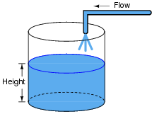
If we introduce a constant flow of water into a cylindrical tank with water, the water level inside that tank will rise at a constant rate over time:
|
|
In calculus terms, we would say that the tank integrates water flow into water height. That is, one quantity (flow) dictates the rate-of-change over time of another quantity (height).
Like the water tank, electrical capacitance also exhibits the phenomenon of integration with respect to time. Which electrical quantity (voltage or current) dictates the rate-of-change over time of which other quantity (voltage or current) in a capacitance? Or, to re-phrase the question, which quantity (voltage or current), when maintained at a constant value, results in which other quantity (current or voltage) steadily ramping either up or down over time?
Challenge question: can you think of a way we could exploit the similarity of capacitive voltage/current integration to simulate the behavior of a water tank's filling, or any other physical process described by the same mathematical relationship?
Notes:
The concept of integration doesn't have to be overwhelmingly complex. Electrical phenomena such as capacitance and inductance may serve as excellent contexts in which students may explore and comprehend the abstract principles of calculus. The amount of time you choose to devote to a discussion of this question will depend on how mathematically adept your students are.
Hopefully, the challenge question will stir your students' imaginations, as they realize the usefulness of electrical components as analogues for other types of physical systems.
Question 10:
|
One of the fundamental principles of calculus is a process called integration. This principle is important to understand because it is manifested in the behavior of inductance. Thankfully, there are more familiar physical systems which also manifest the process of integration, making it easier to comprehend.
If we introduce a constant flow of water into a cylindrical tank with water, the water level inside that tank will rise at a constant rate over time:

|
|
In calculus terms, we would say that the tank integrates water flow into water height. That is, one quantity (flow) dictates the rate-of-change over time of another quantity (height).
Like the water tank, electrical inductance also exhibits the phenomenon of integration with respect to time. Which electrical quantity (voltage or current) dictates the rate-of-change over time of which other quantity (voltage or current) in an inductance? Or, to re-phrase the question, which quantity (voltage or current), when maintained at a constant value, results in which other quantity (current or voltage) steadily ramping either up or down over time?
Challenge question: can you think of a way we could exploit the similarity of inductive voltage/current integration to simulate the behavior of a water tank's filling, or any other physical process described by the same mathematical relationship?
Notes:
The concept of integration doesn't have to be overwhelmingly complex. Electrical phenomena such as capacitance and inductance may serve as excellent contexts in which students may explore and comprehend the abstract principles of calculus. The amount of time you choose to devote to a discussion of this question will depend on how mathematically adept your students are.
Question 11:
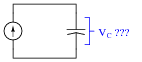
Describe what happens to the capacitor voltage in this circuit over time as it is charged by the constant-current source:
|
|
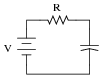
Now, determine the ideal values for V and R that will result in similar behavior in a capacitor circuit powered by a voltage source rather than a current source:
|
|
Your answers will, of course, be qualitative rather than quantitative. Explain whether or not the time constant for the voltage-source-powered circuit ought to be large or small, and why.
Notes:
In this question, I ask students to identify the behavior of a true integrator circuit, and then contrast it with the behavior of what is more accurately known as a first-order lag circuit (the RC circuit powered by the voltage source). Of course, the two circuits do not behave the same, but through judicious choices of V and C, one can make the "lag" circuit closely mimic the true integrator circuit over a practical range of capacitor voltage.
Question 12:
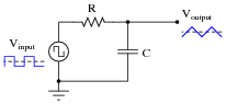
It is relatively easy to design and build an electronic circuit to make square-wave voltage signals. More difficult to engineer is a circuit that directly generates triangle-wave signals. A common approach in electronic design when triangle waves are needed for an application is to connect a passive integrator circuit to the output of a square-wave oscillator, like this:
|
|
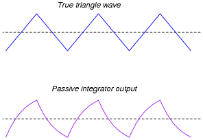
Anyone familiar with RC circuits will realize, however, that a passive integrator will not output a true triangle wave, but rather it will output a waveshape with "rounded" leading and trailing edges:
|
|
What can be done with the values of R and C to best approximate a true triangle wave? What variable must be compromised to achieve the most linear edges on the integrator output waveform? Explain why this is so.
Notes:
This question asks students to recognize conflicting design needs, and to balance one need against another. Very practical skills here, as real-life applications almost always demand some form of practical compromise in the design stage.
If students cannot figure out what must be sacrificed to achieve waveshape linearity, tell them to build such a circuit and see for themselves!
Question 13:
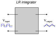
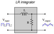
Design a passive integrator circuit using a resistor and inductor rather than a resistor and capacitor:
|
|
|
|
In addition to completing the inductor circuit schematic, qualitatively state the preferred values of L and R to achieve an output waveform most resembling a true triangle wave. In other words, are we looking for a large or small inductor; a large or small resistor?
|
|
For maximum "triangle-like" waveshape, choose a large value for L and a small value for R.
Follow-up question: explain how the choices of values for L and R follow the same reasoning as the choices for R and C in an RC passive integrator circuit.
Notes:
Explain to your students that although LR integrator circuits are possible, they are almost never used. RC circuits are much more practical. Ask them to determine why this is!
Question 14:
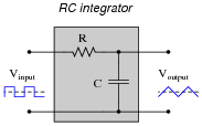
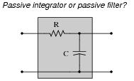
When you look at the schematic diagram for a passive integrator circuit, it ought to remind you of another type of circuit you've seen before: a passive filter circuit:
|
|
What specific type of passive filter does a passive integrator circuit resemble? Is the resemblance the same for LR integrators as well, or just RC integrators? What does this resemblance tell you about the frequency response of a passive integrator circuit?
Notes:
This question is fairly easy, and provides a logical step to prepare students for frequency-domain analysis of passive integrator circuits.
Question 15:
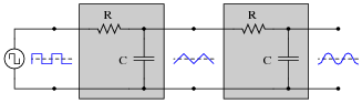
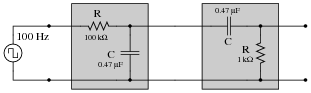
A "cheap" way to electronically produce waveforms resembling sine waves is to use a pair of passive integrator circuits, one to convert square waves into pseudo-triangle waves, and the next to convert pseudo-triangle waves into pseudo-sine waves:
|
|
From Fourier's theory, we know that a square wave is nothing more than a series of sinusoidal waveforms: the fundamental frequency plus all odd harmonics at diminishing amplitudes. Looking at the two integrators as passive filter circuits, explain how it is possible to get a pseudo-sine wave from a square wave input as shown in the above diagram. Also, explain why the final output is not a true sine wave, but only resembles a sine wave.
Challenge question: does the output waveshape more closely resemble a sine wave when the source frequency is increased or decreased?
Notes:
Once students have a conceptual grasp on Fourier theory (that non-sinusoidal waveshapes are nothing more than series of superimposed sinusoids, all harmonically related), they possess a powerful tool for understanding new circuits such as this. Of course, it is possible to understand a circuit such as this from the perspective of the time domain, but being able to look at it from the perspective of the frequency domain provides one more layer of insight.
Incidentally, one may experiment with such a circuit using 0.47 mF capacitors, 1 kW resistors, and a fundamental frequency of about 3 kHz. Viewing the output waveform amplitudes with an oscilloscope is insightful, especially with regard to signal amplitude!
Question 16:
Complete the following sentences with one of these phrases: ßhorter than," "longer than," or ëqual to". Then, explain why the time constant of each circuit type must be so.
- Passive integrator circuits should have time constants that are (fill-in-the-blank) the period of the waveform being integrated.
- Passive differentiator circuits should have time constants that are (fill-in-the-blank) the period of the waveform being differentiated.
Notes:
If students don't understand why this is, let them work through an example problem, to see what the output waveform(s) would look like for various periods and time constants. Remember to stress what an ideal integrator or differentiator is supposed to do!
Question 17:
|
�f(x) dx Calculus alert! |
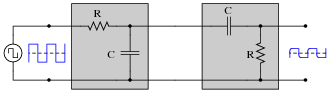
|
|
You recognize one of the RC networks as a passive integrator, and the other as a passive differentiator. What does the likeness of the output waveform compared to the input waveform indicate to you about differentiation and integration as functions applied to waveforms?
Follow-up question: this circuit will not work as shown if both R values are the same, and both C values are the same as well. Explain why, and also describe what value(s) would have to be different to allow the original square-waveshape to be recovered at the final output terminals.
Notes:
That integration and differentiation are inverse functions will probably be obvious already to your more mathematically inclined students. To others, it may be a revelation.
If time permits, you might want to elaborate on the limits of this complementarity. As anyone with calculus background knows, integration introduces an arbitrary constant of integration. So, if the integrator stage follows the differentiator stage, there may be a DC bias added to the output that is not present in the input (or visa-versa!).
|
In a circuit such as this where integration precedes differentiation, ideally there is no DC bias (constant) loss:
|
However, since these are actually first-order "lag" and "lead" networks rather than true integration and differentiation stages, respectively, a DC bias applied to the input will not be faithfully reproduced on the output. Whereas a true integrator would take a DC bias input and produce an output with a linearly ramping bias, a passive integrator will assume an output bias equal to the input bias.f Therefore, the subsequent differentiation stage, perfect or not, has no slope to differentiate, and thus there will be no DC bias on the output.
Incidentally, the following values work well for a demonstration circuit:
|
|
Footnotes:
f If this is not apparent to you, I suggest performing Superposition analysis on a passive integrator (consider AC, then consider DC separately), and verify that VDC(out) = VDC(in). A passive differentiator circuit would have to possess an infinite time constant (t = �) in order to generate this ramping output bias!
Question 18:
|
�f(x) dx Calculus alert! |
|
|
|
|
Notes:
Ask your students to frame their answers in a practical context, such as speed and distance for a moving object (where speed is the time-derivative of distance and distance is the time-integral of speed).
Question 19:
|
�f(x) dx Calculus alert! |
|
|
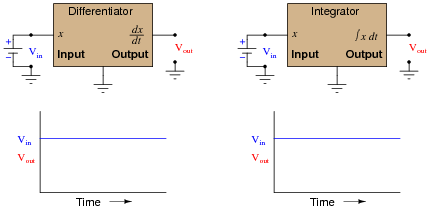
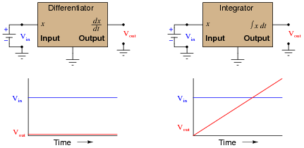
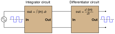
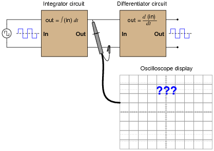
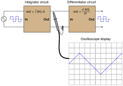
Based on what you know about differentiation and differentiator circuits, what must the signal look like in between the integrator and differentiator circuits to produce a final square-wave output? In other words, if we were to connect an oscilloscope in between these two circuits, what sort of signal would it show us?
|
|
|
|
Follow-up question: what do the schematic diagrams of passive integrator and differentiator circuits look like? How are they similar to one another and how do they differ?
Notes:
This question introduces students to the concept of integration, following their prior familiarity with differentiation. Since they should already be familiar with other examples of inverse mathematical functions (arcfunctions in trigonometry, logs and powers, squares and roots, etc.), this should not be too much of a stretch. The fact that we may show them the cancellation of integration with differentiation should be proof enough.
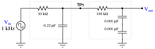
In case you wish to demonstrate this principle "live" in the classroom, I suggest you bring a signal generator and oscilloscope to the class, and build the following circuit on a breadboard:
|
|
The output is not a perfect square wave, given the loading effects of the differentiator circuit on the integrator circuit, and also the imperfections of each operation (being passive rather than active integrator and differentiator circuits). However, the wave-shapes are clear enough to illustrate the basic concept.
Question 20:
When a circuit designer needs a circuit to provide a time delay, he or she almost always chooses an RC circuit instead of an LR circuit. Explain why this is.
Notes:
The answer given here is purposely minimal. You should ask your students to give responses more thoughtful than this! Ask them why capacitors are cheaper than inductors. Ask them to explain what is meant by ëasier to work with," in technical terms.
Question 21:
An LR differentiator circuit is used to convert a triangle wave into a square wave. One day after years of proper operation, the circuit fails. Instead of outputting a square wave, it outputs a triangle wave, just the same as the waveform measured at the circuit's input. Determine what the most likely component failure is in the circuit.
Follow-up question: this is not the only possible failure, but it is the most likely. Explain what the other failure(s) could be, and also why the one given here is most likely.
Notes:
There are only two components in this circuit, so determining possible failures should not be a problem at all. To distinguish between the inductor having failed versus the resistor having failed, one needs to know which type of component failures are more likely (and why!).
Question 22:
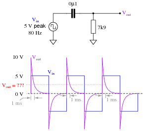
Calculate the output voltage of this passive differentiator circuit 1 millisecond after the rising edge of each positive square wave pulse (where the square wave transitions from -5 volts to +5 volts):
|
|
Notes:
This question is nothing more than an exercise in time-constant circuit calculations: determining how far the output voltage has decayed from its peak of 10 volts after 1 millisecond. Ask your students to share their techniques for problem-solving with the whole class.
Question 23:
Calculate the output voltage of this passive differentiator circuit 150 microseconds after the rising edge of each "clock" pulse (where the square wave transitions from 0 volts to +5 volts):
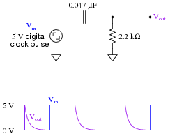
|
|
Notes:
This question is nothing more than an exercise in time-constant circuit calculations: determining how far the output voltage has decayed from its peak of 5 volts after 150 ms. Ask your students to share their techniques for problem-solving with the whole class.
Question 24:
A passive differentiator is used to ßhorten" the pulse width of a square wave by sending the differentiated signal to a "level detector" circuit, which outputs a "high" signal (+5 volts) whenever the input exceeds 3.5 volts and a "low" signal (0 volts) whenever the input drops below 3.5 volts:
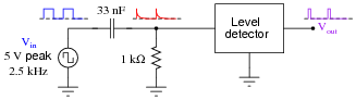
|
|
Each time the differentiator's output voltage signal spikes up to +5 volts and quickly decays to 0 volts, it causes the level detector circuit to output a narrow voltage pulse, which is what we want.
Calculate how wide this final output pulse will be if the input (square wave) frequency is 2.5 kHz.
Notes:
This question requires students to calculate a length of time in an RC circuit, given specific voltage levels and component values. It is a very practical question, as it may be necessary to build or troubleshoot such a circuit some day!
Question 25:
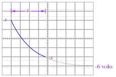
A passive integrator circuit is energized by a square wave signal with a peak-to-peak amplitude of 12 volts and a frequency of 65.79 Hz:
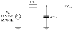
|
|
Determine the peak-to-peak voltage of the output waveform:
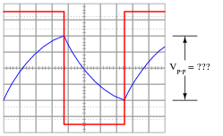
|
|
Hint: the output waveform will be centered exactly half-way between the two peaks of the input square wave as shown in the oscilloscope image. Do not base your answer on relative sizes of the two waveforms, as I have purposely skewed the calibration of the oscilloscope screen image so the two waveforms are not to scale with each other.
Follow-up question: the components comprising this circuit are improperly sized if it is actually expected to function as a reasonably accurate integrator. Suggest better component values for the frequency of signal being integrated.
Challenge question: write a formula that solves for this peak-to-peak output voltage (Vout) given the peak-to-peak input voltage (Vin), resistor value R, capacitor value C, and signal frequency f.
Notes:
This is an interesting problem to set up. Ask your students what approach they used, so they all can see multiple problem-solving techniques. I based my own solution on the RC circuit decay equation e-t / t with x volts being my starting condition and -6 volts being my final condition (if time t is infinite), then I just solved for x. With my method, x is the peak signal voltage, not the peak-to-peak, so I just doubled it to get the final answer.
|
|
My own answer for the challenge question is this:
|
Your mileage may vary . . .