Ammeter design
Question 1:
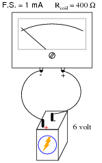
What would happen to this meter movement, if connected directly to a 6-volt battery?
|
|
Notes:
When an electromechanical meter movement is overpowered, causing the needle to ßlam" all the way to one extreme end of motion, it is commonly referred to as "pegging" the meter. I've seen meter movements that have been "pegged" so badly that the needles are bent from hitting the stop!
Based on your students knowledge of meter movement design, ask them to tell you what they think might become damaged in a severe over-power incident such as this. Tell them to be specific in their answers.
Question 2:
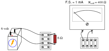
We know that connecting a sensitive meter movement directly in series with a high-current circuit is a Bad Thing. So, I want you to determine what other component(s) must be connected to the meter movement to limit the current through its coil, so that connecting the circuit in series with a 1-amp circuit results in the meter's needle moving exactly to the full-scale position.
|
|
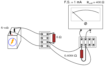
In your diagram, show both the extra component(s) and the manner in which the meter assembly will be connected to the battery/resistor circuit to measure current.
|
|
Follow-up question: given the 0 to 1 amp range of the ammeter created by the 0.4004 W ßhunt" resistor, how much current will the meter actually register when connected in series with the 6 volt battery and 6 ohm resistor? Is this the real current, or is the meter giving us a false indication?
Notes:
Beginning students sometimes feel "lost" when trying to answer a question like this. They may know how to apply Ohm's Law to a circuit, but they do not know how to design a circuit that makes use of Ohm's Law for a specific purpose. If this is the case, you may direct their understanding through a series of questions such as this:
- �
- Why does the meter movement "peg" if directly connected to the battery?
- �
- What type of electrical component could be used to direct current äway" from the movement, without limiting the measured current?
- �
- How might we connect this component to the meter (series or parallel)? (Draw both configurations and let the student determine for themselves which connection pattern fulfills the goal of limiting current to the meter.)
The follow-up question is quite interesting, and causes students to carefully evaluate the performance of the ammeter they've "created". At root, the problem is similar to that of voltmeter loading, except of course that we're dealing with ammeters here rather than voltmeters.
Question 3:
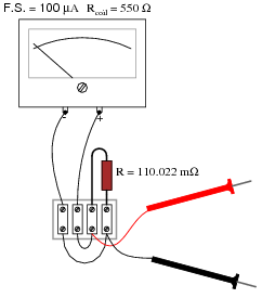
Determine the measurement range of this ammeter:
|
|
Notes:
Determining the ranges for this ammeter is simply an exercise in Ohm's Law. It is very important that your students recognize the shunt resistor's value as being in milliohms and not Megaohms! Yes, there is a difference between a lower-case letter "m" and a capital letter "M"!
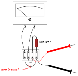
Question 4:
What will happen to the function of this ammeter circuit, if the wire marked in the illustration were to fail open?
|
|
Notes:
Some students may think the ammeter will fail to respond at all with an open resistor, because they associate öpen" faults with lack of current, and lack of current with zero response from the meter movement. Careful examination of the circuit, however, reveals that the exact opposite will happen.
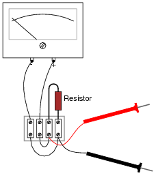
Question 5:
What will happen to the function of this ammeter circuit, if its resistor were to fail open?
|
|
Notes:
Some students may think the ammeter will fail to respond at all with an open resistor, because they associate öpen" faults with lack of current, and lack of current with zero response from the meter movement. Careful examination of the circuit, however, reveals that the exact opposite will happen.
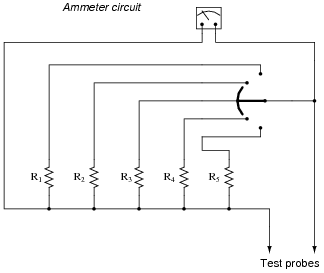
Question 6:
Shown here is an ammeter circuit with a special type of selector switch, called a make-before-break selector:
|
|
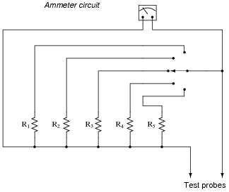
This special kind of selector switch is important to have in an ammeter circuit such as the one shown above. If we were to build such a similar ammeter using a normal (break-before-make) selector switch, the meter would be susceptible to damage during normal use:
|
|
Explain why the first circuit design is superior to the second, and what form of use would prove damaging to the second design (but not to the first).
Notes:
Another solution to the break-before-make problem is to use a ring shunt circuit rather than have an independent range resistor for each current measurement range.
Question 7:
Ideally, should an ammeter have a very low input resistance, or a very high input resistance (input resistance being the amount of electrical resistance intrinsic to the meter, as measured between its test leads)? Explain your answer.
Notes:
The answer to this question is related to the very important principle of meter loading. Technicians, especially, have to be very aware of meter loading, and how erroneous measurements may result from it. The answer is also related to how ammeters are connected with the circuits under test: always in series!
Question 8:
For any given range of current measurement, what design parameter(s) of an electromechanical ammeter influence its input resistance? In other words, to approach the ïdeal" input resistance of an ammeter, for any given range, what component values are optimum?
Challenge question: is it possible to improve the performance of an ammeter's meter movement, as per the recommendations given here, by adding resistors to it? If so, how?
Notes:
If your students have already studied voltmeter design, you might want to ask them to compare the (single) design factor influencing sensitivity (öhms-per-volt") in an electromechanical voltmeter with the two factors listed in the answer to this question. Why is the meter movement coil resistance not a factor in voltmeter sensitivity, but it is in ammeter sensitivity? Challenge your students with this question, by having them propose some example voltmeter circuits and ammeter circuits with different coil resistances. Let them figure out how to set up the problems, rather than you setting up the problems for them!
Some students may suggest that the effective coil resistance of a meter movement may be decreased with the addition of a shunt resistance inside the movement. If anyone proposes this solution, work through the calculations of an example ammeter circuit on the whiteboard with the class and see what the effect is!
Question 9:
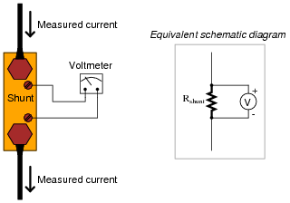
Shunt resistors are often used as current-measuring devices, in that they are designed to drop very precise amounts of voltage as large electric currents pass through them. By measuring the amount of voltage dropped by a shunt resistor, you will be able to determine the amount of current going through it:
|
|
Suppose that a shunt resistance is labeled with the following rating: 150 A , 50 mV. What is the resistance of this shunt, in ohms? Express your answer in metric notation, scientific notation, and plain decimal notation.
Scientific notation: 3.333 ×10⁻⁴ W
Plain decimal notation: 0.0003333 W
Notes:
Ask your students how they think a resistor could be made with such a low resistance (a tiny fraction of an ohm!). What do they think a shunt resistor would look like in real life? If you happen to have a shunt resistor available in your classroom, show it to your students after they express their opinions on its construction.
Question 10:
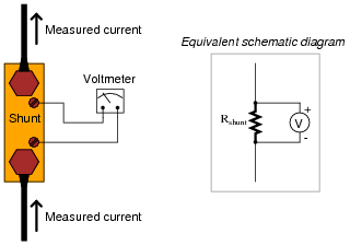
Shunt resistors used for precision current measurement always have four terminals for the electrical connections, even though normal resistors only have two:
|
|
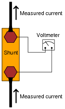
Explain what would be wrong with connecting the voltmeter movement directly to the same two terminals conducting high current through the shunt resistor, like this:
|
|
Challenge question: draw a schematic diagram showing all stray resistances within the two-wire shunt connection circuit, in order to clarify the concept.
Notes:
Though a few fractions of an ohm of ßtray" resistance may not seem like much, they are significant when contrasted against the already (very) low resistance of the shunt resistor's body.
One of the conceptual difficulties I've encountered with students on numerous occasions is confusion over how much resistance, voltage, current, etc., constitutes a ßignificant" amount. For example, I've had students tell me that the difference between 296,342.5 ohms and 296,370.9 ohms is "really big," when in fact it is less than ten thousandths of a percent of the base resistance values. Students simply subtract the two resistances and obtain 28.4 ohms, then think that "28.4" is a significant quantity because it is comparable to some of the other values they're used to dealing with (100 ohms, 500 ohms, 1000 ohms, etc.).
Conversely, students may fail to see the significance of a few hundredths of an ohm of stray resistance in a shunt resistor circuit, when the entire resistance of the shunt resistor itself is only a few hundredths of an ohm. What matters most in problems of accuracy is the percentage or error, not the absolute value of the error itself. This is another practical application of estimating skills, which you should reinforce at every opportunity.
Question 11:
Shunt resistors, being very low in resistance, are usually made from relatively large masses of metal. Their precise resistance is calibrated through a process known as trimming, where a technician takes a metal file and "trims" metal from the shunt conductor until the resistance reaches its correct value. This, of course, only works if the shunt resistor is intentionally manufactured with a resistance that is too low. Like the old carpenter's joke goes, Ï cut the board twice and it's still too short!"
Being that shunt resistors have such incredibly low resistance values, how do we measure the resistance of a shunt with high accuracy during the "trimming" process? The resistance of a shunt is far too low for an average handheld or even benchtop ohmmeter to measure with precision, and specialized low-resistance ohmmeters such as the Kelvin Double Bridge are quite expensive. If you were given the task of trimming a shunt resistor for use in an ammeter, and you only possessed average pieces of test equipment, how could you do it?
Notes:
The answer to this question is deceptively simple, yet extremely practical. Sure, it would be nice to have the best possible test and calibration equipment available to us at any time in our own laboratory, but we must be realistic. It is extremely important for your students that they engage in discussion on problems like this from a practical perspective. It is your task and your privilege as their instructor to bring your own experience into such discussions and challenge students with realistic obstacles to their (often) idealistic expectations.
Question 12:
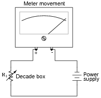
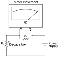
An important step in building any analog voltmeter or ammeter is to accurately determine the coil resistance of the meter movement. In electrical metrology, it is often easier to obtain extremely precise (ßtandard") resistance values than it is to obtain equally precise voltage or current measurements. One technique that may be used to determine the coil resistance of a meter movement without need to accurately measure voltage or current is as follows.
First, connect a decade box type of variable resistance in series with a regulated DC power supply, then to the meter movement to be tested. Adjust the decade box's resistance so that the meter movement moves to some precise point on its scale, preferably the full-scale (100%) mark. Record the decade box's resistance setting as R1:
|
|
Then, connect a known resistance in parallel with the meter movement's terminals. This resistance will be known as Rs, the shunt resistance. The meter movement deflection will decrease when you do this. Re-adjust the decade box's resistance until the meter movement deflection returns to its former place. Record the decade box's resistance setting as R2:
|
|
The meter movement's coil resistance (Rcoil) may be calculated following this formula:
|
Your task is to show where this formula comes from, deriving it from Ohm's Law and whatever other equations you may be familiar with for circuit analysis.
Hint: in both cases (decade box set to R1 and set to R2), the voltage across the meter movement's coil resistance is the same, the current through the meter movement is the same, and the power supply voltage is the same.
|
|
Since we know that the meter's voltage is the same in the two scenarios, we may set these equations equal to each other:
|
Note: the double-bars in the above equation represent the parallel equivalent of Rcoil and Rs, for which you will have the substitute the appropriate mathematical expression.
Notes:
This problem is really nothing more than an exercise in algebra, although it also serves to show how precision electrical measurements may be obtained by using standard resistors rather than precise voltmeters or ammeters.
Question 13:
| Don't just sit there! Build something!! |
Learning to mathematically analyze circuits requires much study and practice. Typically, students practice by working through lots of sample problems and checking their answers against those provided by the textbook or the instructor. While this is good, there is a much better way.
You will learn much more by actually building and analyzing real circuits, letting your test equipment provide the änswers" instead of a book or another person. For successful circuit-building exercises, follow these steps:
- 1.
- Carefully measure and record all component values prior to circuit construction.
- 2.
- Draw the schematic diagram for the circuit to be analyzed.
- 3.
- Carefully build this circuit on a breadboard or other convenient medium.
- 4.
- Check the accuracy of the circuit's construction, following each wire to each connection point, and verifying these elements one-by-one on the diagram.
- 5.
- Mathematically analyze the circuit, solving for all values of voltage, current, etc.
- 6.
- Carefully measure those quantities, to verify the accuracy of your analysis.
- 7.
- If there are any substantial errors (greater than a few percent), carefully check your circuit's construction against the diagram, then carefully re-calculate the values and re-measure.
Avoid very high and very low resistor values, to avoid measurement errors caused by meter "loading". I recommend resistors between 1 kW and 100 kW, unless, of course, the purpose of the circuit is to illustrate the effects of meter loading!
One way you can save time and reduce the possibility of error is to begin with a very simple circuit and incrementally add components to increase its complexity after each analysis, rather than building a whole new circuit for each practice problem. Another time-saving technique is to re-use the same components in a variety of different circuit configurations. This way, you won't have to measure any component's value more than once.
Notes:
It has been my experience that students require much practice with circuit analysis to become proficient. To this end, instructors usually provide their students with lots of practice problems to work through, and provide answers for students to check their work against. While this approach makes students proficient in circuit theory, it fails to fully educate them.
Students don't just need mathematical practice. They also need real, hands-on practice building circuits and using test equipment. So, I suggest the following alternative approach: students should build their own "practice problems" with real components, and try to mathematically predict the various voltage and current values. This way, the mathematical theory "comes alive," and students gain practical proficiency they wouldn't gain merely by solving equations.
Another reason for following this method of practice is to teach students scientific method: the process of testing a hypothesis (in this case, mathematical predictions) by performing a real experiment. Students will also develop real troubleshooting skills as they occasionally make circuit construction errors.
Spend a few moments of time with your class to review some of the "rules" for building circuits before they begin. Discuss these issues with your students in the same Socratic manner you would normally discuss the worksheet questions, rather than simply telling them what they should and should not do. I never cease to be amazed at how poorly students grasp instructions when presented in a typical lecture (instructor monologue) format!
A note to those instructors who may complain about the "wasted" time required to have students build real circuits instead of just mathematically analyzing theoretical circuits:
What is the purpose of students taking your course?
If your students will be working with real circuits, then they should learn on real circuits whenever possible. If your goal is to educate theoretical physicists, then stick with abstract analysis, by all means! But most of us plan for our students to do something in the real world with the education we give them. The "wasted" time spent building real circuits will pay huge dividends when it comes time for them to apply their knowledge to practical problems.
Furthermore, having students build their own practice problems teaches them how to perform primary research, thus empowering them to continue their electrical/electronics education autonomously.
In most sciences, realistic experiments are much more difficult and expensive to set up than electrical circuits. Nuclear physics, biology, geology, and chemistry professors would just love to be able to have their students apply advanced mathematics to real experiments posing no safety hazard and costing less than a textbook. They can't, but you can. Exploit the convenience inherent to your science, and get those students of yours practicing their math on lots of real circuits!