Signal modulation
Question 1:
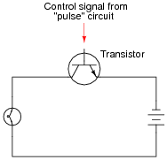
A modern method of electrical power control involves inserting a fast-operating switch in-line with an electrical load, to switch power on and off to it very rapidly over time. Usually, a solid-state device such as a transistor is used:
|
|
This circuit has been greatly simplified from that of a real, pulse-control power circuit. Just the transistor is shown (and not the "pulse" circuit which is needed to command it to turn on and off) for simplicity. All you need to be aware of is the fact that the transistor operates like a simple, single-pole single-throw (SPST) switch, except that it is controlled by an electrical current rather than by a mechanical force, and that it is able to switch on and off millions of times per second without wear or fatigue.
If the transistor is pulsed on and off fast enough, power to the light bulb may be varied as smoothly as if controlled by a variable resistor. However, there is very little energy wasted when using a fast-switching transistor to control electrical power, unlike when a variable resistance is used for the same task. This mode of electrical power control is commonly referred to as Pulse-Width Modulation, or PWM.
Explain why PWM power control is much more efficient than controlling load power by using a series resistance.
Notes:
Students may have a hard time grasping how a light bulb may be dimmed by turning it on and off really fast. The key to understanding this concept is to realize that the transistor's switching time must be much faster than the time it takes for the light bulb's filament to fully heat or fully cool. The situation is analogous to throttling the speed of an automobile by rapidly "pumping" the accelerator pedal. If done slowly, the result is a varying car speed. If done rapidly enough, though, the car's mass averages the ÖN"/ÖFF" cycling of the pedal and results in a nearly steady speed.
This technique is very popular in industrial power control, and is gaining popularity as an audio amplification technique (known as Class D). The benefits of minimal wasted power by the control device are many.
Question 2:
Explain the difference between AM (Amplitude Modulation) and FM (Frequency Modulation).
Notes:
Ask your students to explain which type of modulation their transmitter circuit will use, and what advantages one modulation type may have over the other.
Question 3:
A very important concept in electronics is modulation. Explain what "modulation" means, and give one or two examples of it.
Notes:
There are many examples of modulation that students can find for presentation, and not all of them are electronic. Challenge them to think of scenarios other than modern electronic and/or optical communication schemes where modulation of some kind is employed.
Question 4:
A primitive form of communication long ago was the use of smoke signals: interrupting the rising stream of smoke from a fire by waving a blanket over it so that specific sequences of smoke "puffs" could be seen some distance away. Explain how this is an example of modulation, albeit in a non-electronic form.
Notes:
It is important for students to understand that modulation is not limited to electronic media. Stranger examples than this may be cited as proof. I once spoke with an engineer specializing in vibration measurement who told me of a very odd application of modulation for data communication. He worked on the design of a vibration sensor that would be embedded in the head of an oil well drill bit. This sensor was supposed to transmit information to the surface, thousands of feet up, but could not use radio or any other "normal" data media because of the distances involved and the harsh environment. The solution taken to this unique problem was to have the sensor activate a valve at the drill head which would modulate the flow of drilling mud up to the surface: a byproduct of the drilling process that had to be pumped up to the surface anyway. By pulsing the normally steady mud flow, digital data could be communicated to pressure sensors at the surface, and then converted into
binary data for a computer to archive and translate. Granted, the bit rate was very slow, but the system worked.
An application like this shows how important it is for students to exercise creativity. The really interesting problems in life do not yield to "tried and true" solutions, but can only be overcome through the exercise of creativity and skill. Do everything you can to expose your students to such creative thinking within their discipline(s), and this will help them to become the problem-solvers of tomorrow!
Question 5:
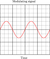
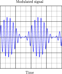
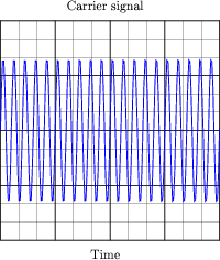
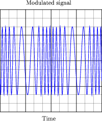
One of the simplest electronic methods of modulation is amplitude modulation, or AM. Explain how a high-frequency carrier signal would be modulated by a lower-frequency signal such as in the case of the two signals shown here in the time domain:

|
|

|
|
|
|
Notes:
I do not expect that students will be able to precisely sketch the modulated waveform, especially when the period of the carrier is so short. However, they should be able to express the general idea of amplitude modulation in some form of drawing or sketch, and that's all I'm interested in seeing from them in response to this question.
Question 6:
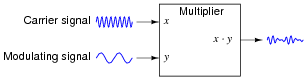
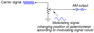
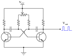
A circuit often used to amplitude-modulate a carrier signal is a multiplier:
|
|
Explain how the instantaneous multiplication of two sine waves results in amplitude modulation. If possible, graph this on a graphing calculator or other computer plotting device.
Notes:
Multiplier circuits are quite useful, and not just for amplitude modulation. The fact that they can be used as amplitude modulators, though, is a concept some students find hard to understand. One illustration that might clear things up is an adjustable voltage divider (since multiplication and division are very closely related):
|
|
Now, such a potentiometer circuit would be totally impractical for any modulating signal frequency measured in Hertz, as the potentiometer would wear out very rapidly from all the motion. It is the principle of modulated voltage division that this circuit helps to communicate, though. Multiplier circuits do the same thing, only multiplying the amplitude of the carrier signal rather than dividing it.
Question 7:
A common modulation technique employed in radio broadcasting is frequency modulation, or FM. Explain how a high-frequency carrier signal would be modulated by a lower-frequency signal such as in the case of the two signals shown here in the time domain:

|
|
|
|
|
|
Notes:
I do not expect that students will be able to precisely sketch the modulated waveform, especially when the period of the carrier is so short. However, they should be able to express the general idea of frequency modulation in some form of drawing or sketch, and that's all I'm interested in seeing from them in response to this question.
Question 8:
At the heart of an FM transmitter is a circuit called a voltage-controlled oscillator, or VCO. Explain what the purpose of a VCO is, and how this directly relates to frequency modulation.
Notes:
Note to your students that VCO circuits are not just used in FM radio transmission. They are also essential to the function of phase-locked loops.
Question 9:
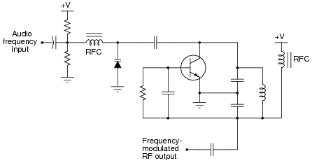
This is a schematic for a very simple VCO:
|
|
The oscillator is of the "Colpitts" design. The key to understanding this circuit's operation is knowing how the varactor diode responds to different amounts of DC bias voltage. Explain how this circuit works, especially how the diode exerts control over the oscillation frequency. Why does the output frequency vary as the control voltage varies? Does the output frequency increase or decrease as the control voltage input receives a more positive voltage?
Note: "RFC" is an acronym standing for Radio-Frequency Choke, an iron-core inductor whose purpose it is to block radio frequency current from passing through.
The output frequency increases as the control voltage becomes more positive.
Notes:
This question is a good review of varactor diode function, as well as frequency modulation theory.
Question 10:
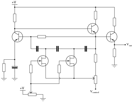
This is a schematic for a simple VCO:
|
|
The oscillator is of the RC "phase shift" design. Explain how this circuit works. Why does the output frequency vary as the control voltage varies? Does the output frequency increase or decrease as the control voltage input receives a more positive voltage?
Hint: the JFETs in this circuit are not functioning as amplifiers!
The output frequency decreases as the control voltage becomes more positive.
Notes:
Not only does this question allow students to examine the workings of a VCO, but it also provides a good review of JFET theory, as well as a practical example of a special application of junction field-effect transistors.
Note: the schematic diagram for this circuit was derived from one found on page 997 of John Markus' Guidebook of Electronic Circuits, first edition. Apparently, the design originated from a Motorola publication on using field effect transistors ("Low Frequency Applications of Field-Effect Transistors," AN-511, 1971).
Question 11:
FM tends to be a far more noise-resistant means of signal modulation than AM. For instance, the "crackling" form of radio interference caused by natural lightning or the "buzzing" noise produced by high-voltage power lines are both easy to hear on an AM radio, but absent on an FM radio. Explain why.
Notes:
Ask students to explain this principle in their own words, and not just repeat the given answer.
Question 12:
When transmitting audio information (such as music and speech) in the form of radio waves, why bother modulating a high-frequency carrier signal? Why not just connect a powerful audio amplifier straight to an antenna and broadcast the audio frequencies directly?
- �
- The necessary size of the antenna.
- �
- Low transmission efficiency from inability to match antenna length to (changing) audio frequency.
- �
- Interference from other (similar) radio transmitters.
Be prepared to explain why each of these factors effectively prohibits radio broadcasts at audio frequencies.
Notes:
The purpose of this question is to have students relate their understanding of basic RF and antenna theory to a very practical problem of broadcasting low-frequency (in this case, audio) information. A fun exercise to do along with this question is to calculate the necessary physical dimensions of a quarter-wave ([(l)/4]) antenna at a frequency of 2 kHz, keeping in mind that l = v/f and v � 3 ×10⁸ meters per second.
Question 13:
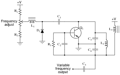
Predict how the output frequency of this voltage-controlled oscillator (VCO) circuit will be affected as a result of the following faults. Consider each fault independently (i.e. one at a time, no multiple faults):
|
|
- �
- Capacitor C1 fails open:
- �
- Inductor L1 fails open:
- �
- Resistor R1 fails open:
- �
- Resistor R2 fails open:
- �
- Inductor L2 fails partially shorted:
For each of these conditions, explain why the resulting effects will occur. Note: the voltage-dependent capacitance of a varactor diode is given by the following equation:
|
Where,
CJ = Junction capacitance
Co = Junction capacitance with no applied voltage
V = Applied reverse junction voltage
- �
- Capacitor C1 fails open: Output frequency increases.
- �
- Inductor L1 fails open: Output frequency decreases.
- �
- Resistor R1 fails open: Output frequency decreases.
- �
- Resistor R2 fails open: Output frequency increases.
- �
- Inductor L2 fails partially shorted: Output frequency increases.
Notes:
The purpose of this question is to approach the domain of circuit troubleshooting from a perspective of knowing what the fault is, rather than only knowing what the symptoms are. Although this is not necessarily a realistic perspective, it helps students build the foundational knowledge necessary to diagnose a faulted circuit from empirical data. Questions such as this should be followed (eventually) by other questions asking students to identify likely faults based on measurements.
Question 14:
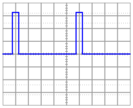
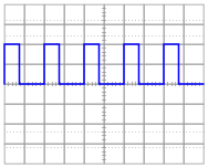
Determine the duty cycle of this square wave signal:
|
|
Notes:
This question challenges students to apply their knowledge of duty cycle to a measurement scenario.
Question 15:
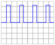
Determine the duty cycle of this square wave signal:
|
|
Notes:
This question challenges students to apply their knowledge of duty cycle to a measurement scenario.
Question 16:
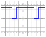
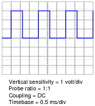
A resistive DC load receives pulse-width modulated (PWM) power from a controller circuit, and an oscilloscope shows the load voltage waveform as such:
|
|
Calculate the duty cycle of this waveform, and also the average power dissipated by the load assuming a load resistance of 1.8 W.
Paverage � 250 W
Follow-up question: which oscilloscope setup parameters (vertical sensitivity, probe ratio, coupling, and timebase) are necessary for performing these calculations? Which parameters are unnecessary, and why?
Notes:
Calculating the duty cycle should be easy. Calculating load power dissipation requires some thought. If your students do not know how to calculate average power, suggest this thought experiment: calculating power dissipation at 0% duty cycle, at 100% duty cycle, and at 50% duty cycle. The relationship between duty cycle and average power dissipation is rather intuitive if one considers these conditions.
If a more rigorous approach is required to satisfy student queries, you may wish to pose another thought experiment: calculate the energy (in units of Joules) delivered to the load for a 50% duty cycle, recalling that Watts equals Joules per second. Average power, then, is calculated by dividing Joules by seconds over a period of one or more whole waveform cycles. From this, the linear relationship between duty cycle and average power dissipation should be clear.
Question 17:
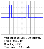
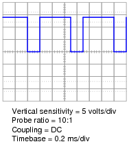
A resistive DC load receives pulse-width modulated (PWM) power from a controller circuit, and an oscilloscope shows the load voltage waveform as such:
|
|
Calculate the duty cycle of this waveform, and also the average power dissipated by the load assuming a load resistance of 10.3 W.
Paverage � 80 W
Follow-up question: which oscilloscope setup parameters (vertical sensitivity, probe ratio, coupling, and timebase) are necessary for performing these calculations? Which parameters are unnecessary, and why?
Notes:
Calculating the duty cycle should be easy. Calculating load power dissipation requires some thought. If your students do not know how to calculate average power, suggest this thought experiment: calculating power dissipation at 0% duty cycle, at 100% duty cycle, and at 50% duty cycle. The relationship between duty cycle and average power dissipation is rather intuitive if one considers these conditions.
If a more rigorous approach is required to satisfy student queries, you may wish to pose another thought experiment: calculate the energy (in units of Joules) delivered to the load for a 50% duty cycle, recalling that Watts equals Joules per second. Average power, then, is calculated by dividing Joules by seconds over a period of one or more whole waveform cycles. From this, the linear relationship between duty cycle and average power dissipation should be clear.
Question 18:
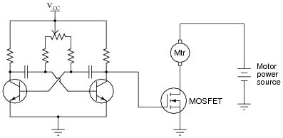
The oscillator circuit in this diagram generates a square wave with an adjustable duty cycle:
|
|
A student desires to use this circuit as the basis for a pulse-width modulation (PWM) power controller, to vary the amount of power delivered to a DC load. Since the oscillator circuit is built to produce weak signals and not deliver power directly to a load, the student adds a power MOSFET to switch heavy load currents:
|
|
Correlate the duty cycle of the oscillator's output signal with motor power. In other words, describe how increases and decreases in signal duty cycle affect the amount of power delivered to the electric motor.
Follow-up question: how do you recommend a suitable oscillator frequency be determined for this motor control circuit? Describe how you might experiment with the circuit to determine a suitable frequency without performing any calculations.
Notes:
As review, ask your students to identify what type of MOSFET this is (type of channel, and either depletion or enhancement mode), and what the proper oscillator signal amplitude should be to drive the MOSFET alternately between cutoff and saturation.
Question 19:
Explain why it is important for the final power transistor(s) in a PWM power control circuit to operate at full cutoff and full saturation, and not in the linear (active) mode in between those two extremes. What might happen if the power transistor(s) were to be less than cut-off or less than saturated when carrying load current?
Notes:
Review with your students what it means for a transistor to be in "cutoff" or in ßaturation," if they are not familiar with these terms or if it has been a while since they have studied this. A clear understanding of this concept is crucial to their being able to understand the efficiency of PWM power control.
Question 20:
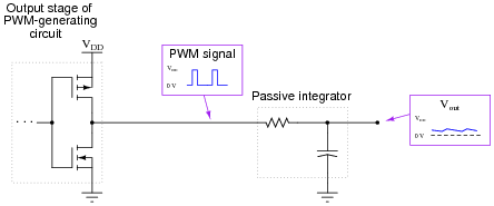
If a pulse-width modulated (PWM) signal is sent to a passive integrator circuit from a circuit capable of both sourcing and sinking current (as is the case with the dual-MOSFET output stage), the output will be a DC voltage (with some ripple):
|
|
Determine the relationship between the PWM signal's duty cycle and the DC voltage output by the integrator. What does this suggest about PWM as a means of communicating information, such as analog data from a measuring device?
Follow-up question #1: why is it important that the circuit generating the PWM signal for the integrator be able to both source and sink current?
Follow-up question #2: what would have to be done to reduce the ripple voltage at the integrator's output?
Notes:
Although it should not be difficult for students to discern the relationship between duty cycle and DC output voltage, the application of this relationship to data communication might be difficult for some students to grasp, especially on their own. Further elaboration on your part may be necessary.
An excellent example of this principle applied is the generation of an analog voltage by a 1-bit digital circuit. This technique is useful in microcontroller systems where output ports may be scarce, provided that ripple voltage (or slow response) is not a problem.
Question 21:
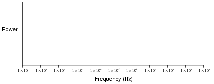
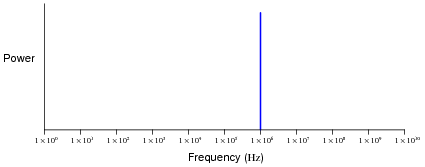
Plot what the frequency spectrum would look like for a pure (undistorted) 1 MHz sine wave:
|
|
|
|
Notes:
This question probes students' knowledge of frequency spectra and logarithmic scales. Note that with a pure sine wave, there is but a single peak on the frequency spectrum.
Question 22:
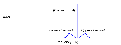
Determine the frequency spectrum for a high-frequency, sine wave "carrier" signal that is amplitude-modulated (AM) by an audio-frequency sine wave signal, as the following block diagram shows:
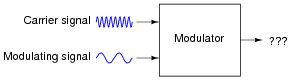
|
|
The spectra for these respective waveforms are shown individually:

|
|
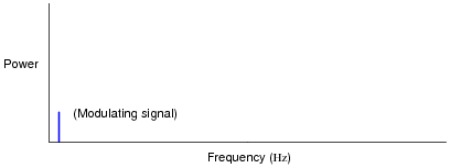
|
|
Plot the modulated signal spectrum here:

|
|
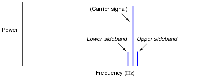
|
|
Follow-up question: if the modulating (audio) signal were increased in frequency, what would the sideband spectra do?
Notes:
The purpose of this question is to get students to recognize where sidebands come from, and how they relate to the frequency spectrum of the amplitude-modulated carrier wave.
In case anyone happens to ask, the symmetrical positioning of the sidebands around the carrier on the answer spectrum implies a linear frequency scale.
Question 23:
Determine the frequency spectrum for a high-frequency, sine wave "carrier" signal that is amplitude-modulated (AM) by an audio-frequency signal with a spectrum of its own. The spectra for these respective waveforms are shown individually:

|
|
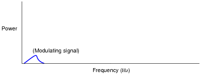
|
|
Plot the modulated signal spectrum here:

|
|
|
|
Notes:
The purpose of this question is to get students to recognize where sidebands come from, and to recognize their symmetry about the carrier peak.
In case anyone happens to ask, the equal scaling of the sidebands around the carrier on the answer spectrum implies a linear frequency scale.
Question 24:
An important measurement of pulse waveforms is duty cycle. Give a precise. mathematical definition for this term.
Also, write an equation solving for pulse width given duty cycle (D) and frequency (f).
|
I'll let you figure out how to write an equation solving for pulse width (ton) in terms of duty cycle and frequency.
Notes:
Duty cycle is a very important concept, as analog information may be conveyed through the variable duty cycle of an otherwise digital pulse waveform. Discuss this application with your students, if time permits.
Question 25:
Determine the duty cycle of this square wave signal:
|
|
Notes:
This question challenges students to apply their knowledge of duty cycle to a measurement scenario.
Question 26:
Determine the duty cycle of this square wave signal:
|
|
Notes:
This question challenges students to apply their knowledge of duty cycle to a measurement scenario.
Question 27:
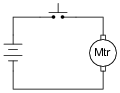
How would a permanent-magnet DC motor respond if the switch in this circuit were repeatedly closed and opened at a very high frequency?
|
|
Would it rotate at full speed, just the same as if the switch were closed all the time? Would it rotate at all? Explain your answer.
Follow-up question: explain how this general principle could be used to control the speed of an electric motor.
Notes:
Since the circuit in this question embodies a general power control principle, it would be good to contrast it against other forms of power control. Ask your students how they think this method of control compares to that of placing a variable resistance in series with the motor. Is the ßwitching" method more or less efficient?
Question 28:
A resistive DC load receives pulse-width modulated (PWM) power from a controller circuit, and an oscilloscope shows the load voltage waveform as such:
|
|
Calculate the duty cycle of this waveform, and also the average power dissipated by the load assuming a load resistance of 2.5 W.
Paverage � 1.5 W
Follow-up question: which oscilloscope setup parameters (vertical sensitivity, probe ratio, coupling, and timebase) are necessary for performing these calculations? Which parameters are unnecessary, and why?
Notes:
Calculating the duty cycle should be easy. Calculating load power dissipation requires some thought. If your students do not know how to calculate average power, suggest this thought experiment: calculating power dissipation at 0% duty cycle, at 100% duty cycle, and at 50% duty cycle. The relationship between duty cycle and average power dissipation is rather intuitive if one considers these conditions.
If a more rigorous approach is required to satisfy student queries, you may wish to pose another thought experiment: calculate the energy (in units of Joules) delivered to the load for a 50% duty cycle, recalling that Watts equals Joules per second. Average power, then, is calculated by dividing Joules by seconds over a period of one or more whole waveform cycles. From this, the linear relationship between duty cycle and average power dissipation should be clear.
Question 29:
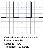
A resistive DC load receives pulse-width modulated (PWM) power from a controller circuit, and an oscilloscope shows the load voltage waveform as such:
|
|
Calculate the duty cycle of this waveform, and also the average power dissipated by the load assuming a load resistance of 40.7 W.
Paverage � 344 W
Follow-up question: which oscilloscope setup parameters (vertical sensitivity, probe ratio, coupling, and timebase) are necessary for performing these calculations? Which parameters are unnecessary, and why?
Notes:
Calculating the duty cycle should be easy. Calculating load power dissipation requires some thought. If your students do not know how to calculate average power, suggest this thought experiment: calculating power dissipation at 0% duty cycle, at 100% duty cycle, and at 50% duty cycle. The relationship between duty cycle and average power dissipation is rather intuitive if one considers these conditions.
If a more rigorous approach is required to satisfy student queries, you may wish to pose another thought experiment: calculate the energy (in units of Joules) delivered to the load for a 50% duty cycle, recalling that Watts equals Joules per second. Average power, then, is calculated by dividing Joules by seconds over a period of one or more whole waveform cycles. From this, the linear relationship between duty cycle and average power dissipation should be clear.
Question 30:
How is pulse-width modulation power control similar to the form of control exerted by TRIACs and SCRs in AC power circuits? How does it differ?
Notes:
Discuss with your students the similarities and differences between these two forms of time-based power control. Of course, PWM is more sophisticated than naturally-commutated SCR and TRIAC control schemes, but it is also more complex and therefore possibly more prone to faults.
Question 31:
Pulse-density modulation (PDM) is closely related to pulse-width modulation (PWM). Describe the similarities and differences in your own words.
Notes:
It should be noted that either pulse stream may be converted into an analog voltage by low-pass filtering, which makes both of these modulation formats very useful.