Mutual inductance
Question 1:
When an electric current is passed through a coil of wire, what phenomenon occurs?
Notes:
Be sure that students understand the answer to this question beyond saying the word, ëlectromagnetism." What, exactly, does this word mean? Reciting an equation is not a sufficient explanation, either. Ask them what some of the factors are that influence the strength of the electromagnetic effect.
Question 2:
When a coil of wire "cuts through" magnetic lines of flux, what phenomenon occurs?
Notes:
Be sure that students understand the answer to this question beyond saying the phrase, ëlectromagnetic induction." What, exactly, does this phrase mean? Reciting an equation is not a sufficient explanation, either. Ask them what some of the factors are that influence the strength of the inductive effect.
Question 3:
If one coil of wire is located very close to another coil of wire, and an electric current is passed through the first coil whose magnitude changes over time, what phenomenon will occur in the second coil of wire?
Notes:
Be sure that students understand the answer to this question beyond saying the phrase, "mutual induction." What, exactly, does this phrase mean? Reciting an equation is not a sufficient explanation, either. Ask them what some of the factors are that influence the strength of the mutual inductive effect.
Question 4:
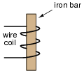
Write the equation describing the voltage induced in this coil, solving for (instantaneous) induced voltage (e) in terms of the instantaneous magnetic flux (f) and the number of turns of wire in the coil:
|
|
Follow-up question: algebraically manipulate this equation to solve for the number of turns (N) given all the other quantities.
Notes:
It should be noted that in this particular case, N is equal to three (counting the turns in the illustrated coil).
Question 5:
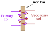
There are two wire windings wrapped around a common iron bar in this illustration, such that whatever magnetic flux may be produced by one winding is fully shared by the other winding:

|
|
Write two equations describing the induced voltage at each winding (ep = ... and es = ...), in each case expressing the induced voltage in terms of the instantaneous magnetic flux (f) and the number of turns of wire in that winding (Np and Ns, respectively).
Then, combine these two equations, based on the fact that the magnetic flux is equal for each winding.
|
|
Then, combining the two equations:
|
Notes:
Obtaining the last equation is an application of the mathematical truth that quantities equal to the same thing are equal to each other (if a = c and b = c, then a = b).
Question 6:
There are two wire windings wrapped around a common iron bar in this illustration, such that whatever magnetic flux may be produced by one winding is fully shared by the other winding:
|
|
Write two equations describing the induced voltage at each winding (ep = ... and es = ...), in each case expressing the induced voltage in terms of the instantaneous current through that winding (ip and is, respectively) and the inductance of each winding (Lp and Ls, respectively).
We know that the induced voltages in the two windings are related to each other by this equation, if there is perfect "coupling" of magnetic flux between the two windings:
|
Knowing this, write two more equations describing induced voltage, this time expressing the induced voltage in each winding in terms of the instantaneous current in the other winding. In other words,
|
|
|
|
Equations describing inductance from one winding to the other:
|
|
Notes:
The first two equations are mere review. The second two equations require algebraic manipulation and substitution between equations.
Question 7:
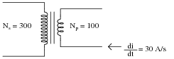
Suppose two wire coils are wound around a common iron core, the "primary" coil with 100 turns of wire and the ßecondary" coil with 300 turns of wire:
|
|
If the inductance of the primary coil is 2 H, what is the inductance of the secondary coil, assuming that it ßees" the exact same magnetic circuit as the first coil (same permeability, same cross-sectional area, same length)?
If an electric current changing at a rate of 30 amps per second passes through the primary coil, how much voltage will be induced in each coil?
If only half the lines of magnetic flux from the primary coil "coupled" with the secondary coil, how much voltage would be induced in the secondary coil, given a primary current rate-of-change of 30 amps per second?
ep = 60 volts
es = 180 volts
If only half the lines of flux coupled the two coils (k = 0.5), then es = 90 volts.
Follow-up question: what do you notice about the ratio of primary and secondary inductances compared with primary and secondary winding turns? Can you generalize this in the form of an equation?
Notes:
The key to this question is determining the ratio of inductances, based on the ratio of turns in the windings. As the answer reveals, it is a nonlinear proportionality. The sentence where I specify the ßame permeability, same cross-sectional area, same length" is a hint to students for what equation they need to find in order to identify the relationship between wire turns and inductance.
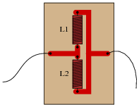
Question 8:
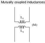
Mutual inductance is the term given to the phenomenon where a change in current through one inductor causes a voltage to be induced in another. When two inductors (L1 and L2) are magnetically "coupled," the mutual inductance (M) relates their voltages and currents as such:
|
|
|
|
When the magnetic coupling between the two inductors is perfect (k = 1), how does M relate to L1 and L2? In other words, write an equation defining M in terms of L1 and L2, given perfect coupling.
Hint:
|
|
|
Challenge question: is mutual inductance expressed in the same unit of measurement that self-inductance is? Why or why not?
Notes:
The solution to this question involves quite a bit of algebraic manipulation and substitution. Of course, it may also be found in many basic electronics textbooks, but the point of this question is for students to see how it may be derived from the equations they already know.
Question 9:
The coefficient of magnetic coupling between two coils affects the amount of mutual inductance between those two coils. This fact should be obvious, as coils not sharing any magnetic flux (k = 0) cannot have any mutual inductance between them.
Write an equation defining M in terms of L1 and L2, when k is something less than 1.
Notes:
Ask your students how they obtained their answer. Of course this equation may be found in many basic electronics textbooks, but the point of this question is for students to see how it may be derived from the equations they already know.
Question 10:
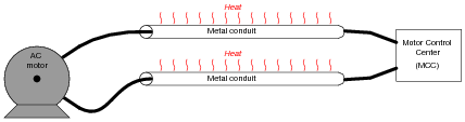
Mutual inductance can exist even in places where we would rather it not. Take for instance the situation of a "heavy" (high-current) AC electric load, where each conductor is routed through its own metal conduit. The oscillating magnetic field around each conductor induces currents in the metal conduits, causing them to resistively heat (Joule's Law, P = I2 R):
|
|
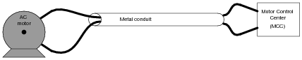
It is standard industry practice to avoid running the conductors of a large AC load in separate metal conduits. Rather, the conductors should be run in the same conduit to avoid inductive heating:
|
|
Explain why this wiring technique eliminates inductive heating of the conduit.
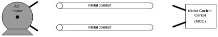
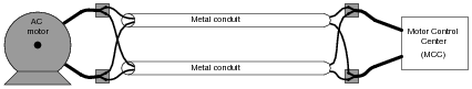
Now, suppose two empty metal conduits stretch between the location of a large electric motor, and the motor control center (MCC) where the circuit breaker and on/off "contactor" equipment is located. Each conduit is too small to hold both motor conductors, but we know we're not supposed to run each conductor in its own conduit, lest the conduits heat up from induction. What do we do, then?
|
|
|
|
Notes:
This wiring technique is very commonly used in industry, where conductor gauges for high-horsepower electric motors can be quite large, and conduits never quite large enough.
Question 11:
Suppose a technician needs 167 mH of inductance in a circuit, but only has 500 mH and 250 mH inductors on hand. He decides he should be able to achieve approximately 167 mH of inductance easily enough by connecting these two inductors in parallel with one another on a printed circuit board:
|
|
However, upon testing this parallel inductor arrangement, the technician finds the total inductance to be significantly less than the 167 mH predicted. Puzzled, he asks a fellow technician for help. The other technician inspects the board, and immediately suggests that the two inductors be re-located with their axes perpendicular to one another. The first technician doesn't understand why the physical location of the inductors should matter. After all, it never mattered how he located resistors and capacitors with respect to one another, so long as their connecting wires (or board traces) went to the right places. Can you explain to him why inductors might be sensitive to physical orientation?
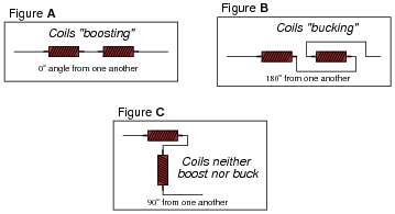
Follow-up question: coils placed in linear proximity to one another will magnetically "link" in such a way as to either "boost" (Figure A) or "buck" (Figure B) one another. If placed perpendicular (90o) to one another, the magnetic linking is nonexistent and the two inductors act as independent entities:
|
|
What trigonometric function (sine, cosine, tangent, cotangent, secant, cosecant) follows this same pattern: full positive at 0o, full negative at 180o, and zero at 90o?
Notes:
A potential point of confusion here is that some students may think the orientation being spoken of is absolute: with reference to the earth's magnetic field. What I'm trying to get them to see, however, is the relationship between the two coils' magnetic fields, which is an entirely different matter. To expose this misunderstanding, ask your students whether or not the position of the printed circuit board with respect to compass directions (north, south, east, or west) would have any effect on these two inductors' combined inductance. For those who mistakenly answer ÿes" to this question, review Faraday's Law of electromagnetic induction: that induced voltage only occurs when there is a change of magnetic flux over time, and that the earth's magnetic field is constant (for all practical purposes).
The follow-up question gets students thinking in terms of the mutual inductance as a function of the physical angle between the two inductors, and relating a pattern (analyzed at three points) to common trig functions. This form of reasoning is very useful in problem-solving, because the ability to see patterns as a function of a certain variable (such as an angle) is the first step in mathematically modeling a system.
Question 12:
Explain what leakage inductance is, in a system of two or more mutually coupled inductors (such as a transformer). In a transformer, is leakage inductance a good thing or a bad thing?
In power distribution transformers, leakage inductance is undesirable. However, there are some applications where leakage inductance is a desirable attribute. Step-up transformers used to power gas-discharge lights, for example, are purposely built to have significant amounts of leakage inductance.
Notes:
After discussing the nature of leakage inductance (what causes it, and how it manifests itself in a transformer circuit), ask your students to explain why we do not want to have leakage inductance in a power distribution transformer, and why we do want to have it in a gas-discharge lighting transformer.