Multiplexers and demultiplexers
Question 1:
| Don't just sit there! Build something!! |
Learning to analyze digital circuits requires much study and practice. Typically, students practice by working through lots of sample problems and checking their answers against those provided by the textbook or the instructor. While this is good, there is a much better way.
You will learn much more by actually building and analyzing real circuits, letting your test equipment provide the änswers" instead of a book or another person. For successful circuit-building exercises, follow these steps:
- 1.
- Draw the schematic diagram for the digital circuit to be analyzed.
- 2.
- Carefully build this circuit on a breadboard or other convenient medium.
- 3.
- Check the accuracy of the circuit's construction, following each wire to each connection point, and verifying these elements one-by-one on the diagram.
- 4.
- Analyze the circuit, determining all output logic states for given input conditions.
- 5.
- Carefully measure those logic states, to verify the accuracy of your analysis.
- 6.
- If there are any errors, carefully check your circuit's construction against the diagram, then carefully re-analyze the circuit and re-measure.
Always be sure that the power supply voltage levels are within specification for the logic circuits you plan to use. If TTL, the power supply must be a 5-volt regulated supply, adjusted to a value as close to 5.0 volts DC as possible.
One way you can save time and reduce the possibility of error is to begin with a very simple circuit and incrementally add components to increase its complexity after each analysis, rather than building a whole new circuit for each practice problem. Another time-saving technique is to re-use the same components in a variety of different circuit configurations. This way, you won't have to measure any component's value more than once.
Notes:
It has been my experience that students require much practice with circuit analysis to become proficient. To this end, instructors usually provide their students with lots of practice problems to work through, and provide answers for students to check their work against. While this approach makes students proficient in circuit theory, it fails to fully educate them.
Students don't just need mathematical practice. They also need real, hands-on practice building circuits and using test equipment. So, I suggest the following alternative approach: students should build their own "practice problems" with real components, and try to predict the various logic states. This way, the digital theory "comes alive," and students gain practical proficiency they wouldn't gain merely by solving Boolean equations or simplifying Karnaugh maps.
Another reason for following this method of practice is to teach students scientific method: the process of testing a hypothesis (in this case, logic state predictions) by performing a real experiment. Students will also develop real troubleshooting skills as they occasionally make circuit construction errors.
Spend a few moments of time with your class to review some of the "rules" for building circuits before they begin. Discuss these issues with your students in the same Socratic manner you would normally discuss the worksheet questions, rather than simply telling them what they should and should not do. I never cease to be amazed at how poorly students grasp instructions when presented in a typical lecture (instructor monologue) format!
I highly recommend CMOS logic circuitry for at-home experiments, where students may not have access to a 5-volt regulated power supply. Modern CMOS circuitry is far more rugged with regard to static discharge than the first CMOS circuits, so fears of students harming these devices by not having a "proper" laboratory set up at home are largely unfounded.
A note to those instructors who may complain about the "wasted" time required to have students build real circuits instead of just mathematically analyzing theoretical circuits:
What is the purpose of students taking your course?
If your students will be working with real circuits, then they should learn on real circuits whenever possible. If your goal is to educate theoretical physicists, then stick with abstract analysis, by all means! But most of us plan for our students to do something in the real world with the education we give them. The "wasted" time spent building real circuits will pay huge dividends when it comes time for them to apply their knowledge to practical problems.
Furthermore, having students build their own practice problems teaches them how to perform primary research, thus empowering them to continue their electrical/electronics education autonomously.
In most sciences, realistic experiments are much more difficult and expensive to set up than electrical circuits. Nuclear physics, biology, geology, and chemistry professors would just love to be able to have their students apply advanced mathematics to real experiments posing no safety hazard and costing less than a textbook. They can't, but you can. Exploit the convenience inherent to your science, and get those students of yours practicing their math on lots of real circuits!
Question 2:
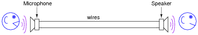
Imagine a telephone system with only one pair of wires stretching between phone units. For the sake of simplicity, let's consider each telephone to be a sound-powered (unamplified) unit, where the voltage produced directly by the microphone drives the speaker on the other end:
|
|
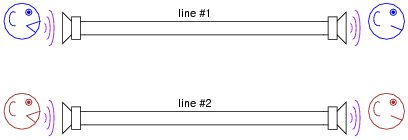
If we were to install a second telephone line to accommodate another pair of people talking to each other, it certainly would work, but it might be expensive to do so because of the cost of wire over the long distance:
|
|
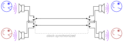
Suppose, though, we installed a set of DPDT switches that switched the two telephone conversations along the same pair of wires (only 1 telephone "line"). This general technique is known as multiplexing. The switches would be synchronized according to clocks at either end of the line, and cycled back and forth repeatedly:
|
|
What would the conversation sound like to either of the listeners if the switch frequency was 1 Hz? What if it was 10 Hz? What if it was 40 kHz?
At 10 Hz, the "choppiness" would be reduced, with only 1/20 of a second's worth of conversation missing every 1/10 of a second from each conversation. It would still be very difficult to listen to, though.
At 40 kHz switching speed, both conversations would sound seamless.
Follow-up question: how can we multiplex more than two conversations along the same pair of telephone wires?
Challenge question: is there a limit as to how many conversations we can multiplex on the same wire pair? If so, what parameters would define this limit?
Notes:
Ask your students why this technique of switching conversations works. How is it possible for audio conversations to sound ßeamless" when half the information is missing from each one (regardless of switching speed)?
Ask your students for answers to the challenge question. If no one has any, give them a hint: how does the bandwidth of the telephone lines impact multiplexing a large number of signals?
Question 3:
Most modern analog oscilloscopes have the ability to display multiple traces on their screens (dual-trace is the standard), even though the CRT itself used by the 'scope may only have one electron gun, and thus only be able to "paint" one flying dot on the screen at a time.
Oscilloscopes with single-gun display tubes achieve dual-trace capability by way of multiplexing the two input channels to the same CRT. There are usually two different modes for this multiplexing, though: alternate and chop.
Explain how these multiplexing techniques work, and what conditions would prompt you to use the two different multiplexing modes. I strongly encourage you to experiment with displaying two different signals on one of these oscilloscopes as your research. You will likely learn far more from a hands-on exercise than if you were to read about it in a book!
Notes:
Don't simply tell your students how the alternate and chop facilities of their oscilloscopes work. Let them experience these two modes of multiplexing directly, with hands-on investigation. If nothing else, this will provide them with additional practice using oscilloscopes.
Question 4:
A variety of practical electronic applications require multiplexing, where several input signals are individually selected, one at a time but very rapidly, to be communicated through a single channel. Telephony systems use this technique to "concentrate" multiple voice conversations over a single wire pair, and most analog dual-trace oscilloscopes use this technique to allow a single-gun CRT to display more than one signal trace on the screen at a time.
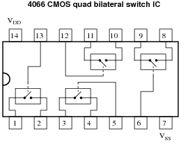
In order to rapidly select (or switch) analog signals in these multiplexing applications, we need some form of semiconductor on/off switch capable of fast switching time, low pass-through (ön" state) impedance, and high blocking (öff" state) impedance. Thankfully, there is such a device commonly and inexpensively produced, called a CMOS bilateral switch:
|
|
This hybrid analog/digital device uses digital logic signals (high/low) to activate the gates of CMOS transistor assemblies to switch analog signals on and off. It is like having four low-current solid-state relays in a single integrated circuit. When the control line is made "high" (standard CMOS logic level), the respective switch goes into its conductive (ön") state. When the control line is made "low," the switch turns off. Because it is MOSFETs we are turning on and off, the control lines draw negligible current (just like CMOS logic gate inputs).
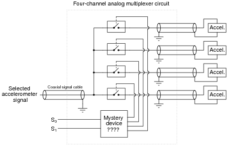
If we are to use such bilateral switches to multiplex analog signals along a common signal line, though, we must add some accessory components to control which switch (out of the four) is active at any given time. Take for instance this circuit where we use four bilateral switches to multiplex the voltage signals from four accelerometers (measuring acceleration on a vibration-testing jig):
|
|
Identify the necessary "mystery device" shown in the schematic, which allows a binary input (S0 and S1 with four combinations of high/low states: 00, 01, 10, and 11) to activate just one bilateral switch at a time.
Notes:
This question serves a few purposes: to introduce students to the 4066 quad bilateral switch, to showcase a practical application for analog multiplexing, and to review a previous subject (decoders).
Question 5:
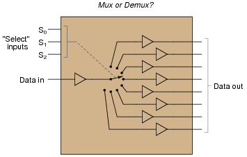
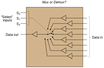
Multiplexers and demultiplexers are often confused with one another by students first learning about them. Although they appear similar, they certainly perform different functions. Shown here is a multiplexer and a demultiplexer, each using a multiple-position switch symbol to indicate the selection functions inside the respective circuits:
|
|
|
|
After identifying which is which, provide definitions for "multiplexer" and "demultiplexer" in your own words.
Notes:
This question forces students to directly face a point of confusion I have noticed over several years of teaching. Ask them where they were able to find definitions for each term.
Question 6:
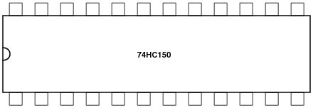
The 74HC150 is a high-speed CMOS (TTL-compatible) integrated circuit multiplexer, also known as a data selector. It is commonly available as a 24 pin DIP "chip." Identify the terminals of a 74HC150, and label them here:
|
|
In particular, note the locations of the four ßelect" terminals, as well as the single output terminal.
What types of electrical "data" may be ßelected" by this particular integrated circuit? For example, can it select an analog waveform, such as human speech from a microphone? Is it limited to discrete TTL signals (low and high, 0 volts and 5 volts DC)? How can you tell?
Challenge question: how could you build an analog signal multiplexer, using components you are familiar with? I recommend you start with something simple, such as a four-channel multiplexer, before attempting something with as many channels as the digital device shown here (74HC150).
Notes:
Datasheets not only provide basic pinout information, but they also reveal important operational characteristics of integrated circuits. In many cases they also show typical applications, which have great educational value. Stress the importance of datasheets to your students with "look-up" exercises such as this, build their ability to interpret the information contained.
In regard to the challenge question, it is a common mistake for students to think they can build an analog signal multiplexer around a digital signal multiplexer. In actuality, they would need a completely different type of device!
Question 7:
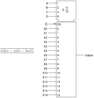
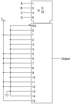
Multiplexers, or data selectors, may be used to generate arbitrary truth table functions. Take for example this Boolean SOP expression, shown beside a symbol for a 16-channel multiplexer:
|
|
Show the wire connections necessary to make the multiplexer output the specified logic states in response to the data select (A, B, C, and D) inputs.
|
|
Notes:
Discuss with your students the significance of using a multiplexer in this fashion: to implement arbitrary logic functions. For those students who may not be familiar with the term, be sure to define the word ärbitrary." It may seem silly, but students often fail to ask for the definitions of words that are new to them, for fear of sounding dumb in front of their peers and in front of you. One more reason to model respect in your classroom, and also to create an atmosphere where students feel comfortable asking any question.
Question 8:
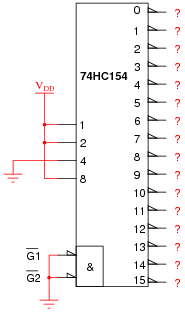
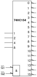
The 74HC154 is a high-speed CMOS (TTL-compatible) integrated circuit decoder with four input lines and sixteen output lines:
|
|
Identify the logic states of all output terminals given the input conditions shown.
Now, identify the logic states for the same circuit, this time with a square wave (on/off pulse) logic signal applied to the enable terminals:
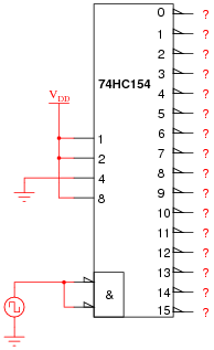
|
|
Notes:
This question previews the use of a decoder as a demultiplexer.
Question 9:
The 74HC154 is a high-speed CMOS (TTL-compatible) integrated circuit decoder, which may also be used as a demultiplexer:
|
|
What terminal(s) do we use for the signal input, if using this chip as a demultiplexer and not just a decoder?
Notes:
Explain to your students that "decoder" and "demultiplexer" are really just two different words for the same device, seeing as how all real decoders come equipped with enable inputs.
Question 10:
The 74HC137 and 74HC237 decoder/demultiplexer integrated circuits have a feature that some other decoder/demultiplexers do not: address latching. Explain what this additional feature is, how it works, and how you would disable the feature if you needed to use one of these integrated circuits in an application not requiring address latching.
Follow-up question: what is the functional difference between the 74HC137 and the 74HC237? How would the respective schematic symbols for these two decoder/demux ICs differ?
Challenge question: think of a practical application where you might need the feature of address latching.
Notes:
The feature of address latching is not hard to understand if students have already studied D-type latches (and/or parallel-in/parallel-out shift registers).
Question 11:
When first learning about encoders, decoders, multiplexers, and demultiplexers, students often get them confused with one another. Write succinct definitions (complete with illustrations) for each of these four digital functions, based on your own research and written using your own words. Also, identify which two of these digital functions are usually performed by the same integrated circuit.
Decoding and demultiplexing are usually performed by the same integrated circuit device. A good example of this is the 74HC154.
Notes:
Here is a good example of where students like to fall on rote memorization, and where such shallow learning strategies often fail. It is imperative that students do their own research and cast these functions into their own personal terms. This way, they will understand the differences rather than just memorize the differences.
Call on individual students to present their findings for this question, and let the classroom be a place where students share their understandings with one another. Let them know that this is important for them to grasp, but do not simply provide ready-made answers for them!
Question 12:
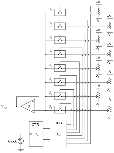
The following schematic diagram shows an eight-step arbitrary waveform generator. The analog multiplexer selects one of the eight potentiometer signals at a time, stepping from one to the next at the pace of the clock pulse:
|
|
Explain what effect a shorted bilateral switch would have on the output waveform. Be as specific as possible.
Notes:
A failed-shorted bilateral switch would create a sort of passive averager circuit between the shorted-switch pot and the selected-switch pot. If your students have difficulty figuring out the effects of this fault, remind them of what a passive averager is, and how it works.
Question 13:
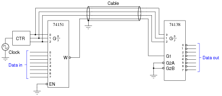
Predict how the operation of this "concentrator" circuit (which takes eight digital inputs and "concentrates" them into a single, multiplexed, communication line to be expanded into eight outputs at the receiving end) will be affected as a result of the following faults. Consider each fault independently (i.e. one at a time, no multiple faults):
|
|
- �
- Clock pulse generator stops pulsing:
- �
- Pin breaks on the W output of 74151 chip, leaving that wire floating:
- �
- Pin breaks on G2A input of 74138 chip, leaving it floating:
- �
- Enable pin breaks on 74151 chip, leaving it floating:
For each of these conditions, explain why the resulting effects will occur.
- �
- Clock pulse generator stops pulsing: Only one channel out of the eight will work, and it works all the time without interruption. Data cannot get through any of the other seven channels.
- �
- Pin breaks on the W output of 74151 chip, leaving that wire floating: All selected outputs on the 74138 chip go low, instead of repeating the respective logic states input at the 74151 chip.
- �
- Pin breaks on G2A input of 74138 chip, leaving it floating: All outputs on the 74138 chip go high, all the time.
- �
- Enable pin breaks on 74151 chip, leaving it floating: All selected outputs on the 74138 chip go low, instead of repeating the respective logic states input at the 74151 chip.
Notes:
The purpose of this question is to approach the domain of circuit troubleshooting from a perspective of knowing what the fault is, rather than only knowing what the symptoms are. Although this is not necessarily a realistic perspective, it helps students build the foundational knowledge necessary to diagnose a faulted circuit from empirical data. Questions such as this should be followed (eventually) by other questions asking students to identify likely faults based on measurements.
Question 14:
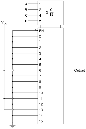
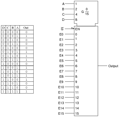
Multiplexers, or data selectors, may be used to generate arbitrary truth table functions. Take for example this truth table, shown beside a symbol for a 16-channel multiplexer:
|
|
Show the wire connections necessary to make the multiplexer output the specified logic states in response to the data select (A, B, C, and D) inputs.
|
|
Follow-up question: what if this multiplexer had an active-low output, like the 74150? How would this change your design for implementing the truth table?
Notes:
Discuss with your students the significance of using a multiplexer in this fashion: to implement arbitrary logic functions. For those students who may not be familiar with the term, be sure to define the word ärbitrary." It may seem silly, but students often fail to ask for the definitions of words that are new to them, for fear of sounding dumb in front of their peers and in front of you. One more reason to model respect in your classroom, and also to create an atmosphere where students feel comfortable asking any question.
Question 15:
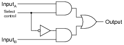
The following schematic diagram is for a two-input selector circuit, which (as the name implies) selects one of two inputs to be sent to the output:
|
|
Determine what state the ßelect control" input line has to be in to select InputA to be sent to the output, and what state it has to be in to select InputB to go to the output.
Notes:
Selector circuits are widely used internally in counter and shift register circuits where digital signals must be selected from multiple sources to achieve certain functions. Be sure your students understand how it works, for they will surely see it later in some application!