Electrical noise and interference
Question 1:
Define what noise means, in the electrical sense of the word. How does electrical noise compare and contrast with audible noise?
Notes:
For a good overview of electrical noise, consult Texas Instruments' online manual, Op Amps For Everyone, sections 10-1 through 10-12.
Question 2:
Define the following noise types, according to how each one is generated in electronic circuits:
- �
- Shot noise
- �
- Thermal ("Johnson") noise
- �
- Flicker (or 1/f) noise
Also, identify the major factor responsible for the amplitude of each noise type.
Thermal noise, also known as Johnson noise, is caused by the random motion of electrons due to thermal energy. As one might guess, this type of noise is proportional to conductor temperature.
Flicker noise, or 1/f noise, is characterized by a magnitude that is inversely proportional to frequency. Little is known about the origins of this type of noise, but it is proportional to the amount of DC current, just like shot noise, and so may be mitigated using the same controls.
Notes:
Noise is a very complex subject in electrical engineering, and most likely beyond the scope of your students' coursework. This question is really just scratching the surface of noise theory.
For a good overview of electrical noise, consult Texas Instruments' online manual, Op Amps For Everyone, sections 10-1 through 10-12.
Question 3:
What is the difference between white noise and pink noise?
White noise in the audio range is generally considered to be pleasing to the human ear. Identify one source of "white" noise that anyone can readily experience for themselves.
With regard to white noise, everyone has heard it at least one in their lives, but most people don't know what to call it!
Notes:
Explain to your students that other colors are used to categorize spectral distributions of different noise types:
- �
- Purple = f2 (directly proportional to square of frequency)
- �
- Blue = f (directly proportional to frequency)
- �
- White = 1 (constant amplitude)
- �
- Pink = 1/f (inversely proportional to frequency)
- �
- Red/Brown = 1/f2 (inversely proportional to square of frequency)
And, of course, there are such noises that do not neatly fall into any of these categories.
For a good overview of electrical noise, consult Texas Instruments' online manual, Op Amps For Everyone, sections 10-1 through 10-12.
Question 4:
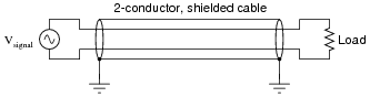
A common mistake made when installing shielded cable is to connect both ends of the cable's shield conductor to earth ground:
|
|
Connecting both ends of a cable's shield conductor to ground creates something called a ground loop. The longer the physical distance between the cable's ends, the worse the "ground loop" problem becomes. Explain why.
Follow-up question: redraw the schematic, showing the noise voltage source(s) as a single AC voltage source symbol in the loop.
Notes:
Note to your students that this problem is far more acute if the cable wiring is single conductor (unbalanced, like a coaxial cable) rather than twisted-pair (balanced). However, even when using twisted-pair cable in a balanced circuit, care should be taken to avoid ground loops so as to not create any unnecessary paths for noise.
In some cases, the noise currents may be so severe that wiring damage results. I (Tony Kuphaldt) used to work as a technician at an aluminum smelter facility where extremely high levels of electrical current were used to smelt aluminum from ore. Due to the nature of the process, several thousand amps of noisy "DC" current traveled through the earth from the "potline" system due to unavoidable ground faults. Earth ground was an electrically noisy connection point at best in that facility! Ground loops were simply not acceptable, as the cable shield wires would conduct enough DC current to actually cause damage in some locations!
To give you a more graphic view of the problem's severity, I saw one instance where a construction contractor touched the tip of an electric drill (safety-grounded, through the extension cord plugged into a wall socket about 30 meters away) to a piece of steel reinforcement bar where concrete was to be poured, and actually drew a spark! Such was the magnitude of ground current at this facility that enough potential existed between the span of distance covered by that extension cord to draw an arc between the two ground points (the rebar, and the safety ground near the receptacle). Ironically, this was one instance where the grounded drill motor case presented a shock hazard to anyone working around the rebar!