Basic ohmmeter use
Question 1:
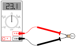
Explain how an ohmmeter is able to measure the resistance of a component (in this case, a light bulb) when there is no battery or other source of power connected to it:
|
|
Also, identify the reading you would expect the ohmmeter to indicate if the light bulb were burnt out (failed öpen").
If the light bulb were burnt open, the ohmmeter would register an extremely large (infinite) amount of resistance.
Notes:
Unlike voltmeters or ammeters, ohmmeters must contain their own power sources. An implication of this fact is that ohmmeters must never be used to measure the resistance of an energized component. Discuss this important caveat with your students, being sure to ask them to explain why connecting an ohmmeter to an energized component might give erroneous measurements (if it doesn't destroy the meter first!).
In regard to the ohmmeter reading for an open bulb, I have found that many math-weak students have a difficult time grasping the differentiating zero from infinity. They recognize both as being extreme conditions (nothing versus everything), but many make the mistake of regarding ïnfinity" as identical to zero. Quite to the contrary, ïnfinity" means bigger than big, and huger than huge. Do not be surprised if one or more of your students harbor this same misconception, and be ready to address it!
Question 2:
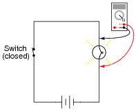
What would be wrong about measuring the resistance of a light bulb while it is being powered by a battery?
|
|
Notes:
This principle is very easy to illustrate, simply by building a "live" circuit and trying to measure the resistance of a known component in that circuit, while energized. Different ohmmeters will, of course, respond differently to this abuse, but none will yield the proper value for that component's resistance.
Question 3:
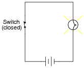
Suppose we needed to determine the resistance of the light bulb in this circuit, while energized:
|
|
Now, we know we cannot simply connect an ohmmeter to an energized circuit, so how is it possible to obtain the resistance measurement we desire?
Challenge question: explain how it would be possible to make these measurements without de-energizing the light bulb (not even once!).
Notes:
Quite often, resistance measurements on a component are not practical because the component cannot be "powered down," or perhaps because the component's resistance is different when energized versus when de-energized (incandescent light bulbs being an excellent example of this). Knowing how to derive a resistance measurement from voltage and current measurements is a valuable skill.
The "challenge" question, to measure light bulb voltage and current without breaking the circuit, is also very practical. Once students figure out how to do this (no, using an inductive ammeter is not an acceptable answer!), it would be a great classroom activity to actually build such a circuit and have students practice the technique on it.
Question 4:
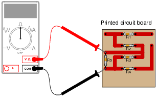
Suppose a technician attempted to measure the resistance of resistor R5 on this printed circuit board:
|
|
What is wrong with doing this?
Follow-up question: what components on this printed circuit board may be measured with the ohmmeter without error?
Notes:
This is very important for students to understand: the fact that the resistance of an individual component cannot be measured in a circuit, unless it is guaranteed that the ohmmeter's measuring current passes through that component only.
Question 5:
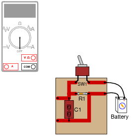
Shown here is a circuit constructed on a PCB (a "Printed Circuit Board"), with copper "traces" serving as wires to connect the components together:
|
|
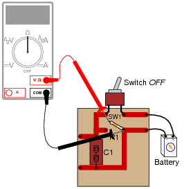
How would the multimeter be used to measure the resistance of the component labeled "R1"? Include these important points in your answer:
- �
- The configuration of the multimeter (selector switch position, test lead jacks)
- �
- The connections of the meter test leads to the circuit
- �
- The state of the switch on the PCB (open or closed)
|
|
Notes:
It is very important that students understand component resistance cannot be measured when the component is energized! In cases such as this, it is necessary to disconnect the component from the rest of the circuit so that only its resistance (and not any other components' resistance) is measured. In other cases, though, it may be acceptable to leave the component in place to take a resistance measurement.
Question 6:
A technician picks up a resistor with the following color bands:
Color code: Brn, Blk, Sil, Gld
Having forgotten the resistor color code, and being too lazy to research the color code in a book, the technician decides to simply measure its resistance with an ohmmeter. The value this technician obtains is 0.6 W.
What is wrong with the technician's measurement?
Notes:
Analog ohmmeters had to be "zeroed" prior to almost every measurement out of necessity, to give accurate measurements despite changes in internal battery voltage. Modern digital ohmmeters do not have this problem, but the lack of a "zeroing" procedure can lead to errors due to uncompensated test lead resistance. Your students should research the proper use of their own digital meters in this regard.
Question 7:
A technician picks up a resistor with the following color bands:
Color code: Org, Wht, Blu, Gld
Having forgotten the resistor color code, and being too lazy to research the color code in a book, the technician decides to simply measure its resistance with an ohmmeter. Holding one lead of the resistor and one test lead of the ohmmeter between the thumb and index finger of the left hand, and the other resistor lead and meter test lead between the thumb and index finger of the right hand (to keep each test lead of the meter in firm contact with the respective leads of the resistor), the technician obtains a resistance measurement of 1.5 MW.
What is wrong with the technician's measurement?
Notes:
This is a very common mistake made by beginning students of electronics: holding resistors improperly when measuring their resistance values. Discuss with your students some alternative methods of maintaining resistor lead contact with the meter probes so that the person's body does not become part of the resistance being measured.
Question 8:
What is a megger, and what type of resistance measurements would it typically be used for? Explain how the design of a "megger" differs from that of a normal ohmmeter.
Also, explain how improper use of a "megger" may actually be hazardous, either to the operator of the meter or to the circuit under test.
Follow-up question: what is a hi-pot meter, and what function is it typically used for?
Challenge question: why are special, high-voltage ohmmeters even needed? What's wrong with using a regular ohmmeter that outputs just a few volts to measure resistance? What does the existence of these specialized ohmmeter types tell us about the nature of electrical resistance?
Notes:
"Meggers" are very useful tools, but they can cause damage as well. Your students need to be aware of proper and improper uses of "meggers" before they are entrusted with the use of one.
The challenge question is worth exploring if time permits! In real life, the simplicity of Ohm's Law is deceptive . . .
Question 9:
High-precision ohmmeters use a four-wire electrical connection to the resistance under test, rather than a two-wire connection. Explain how the four-wire system works, and why it provides better accuracy than two-wire resistance measurement.
Notes:
It is one thing to explain how four-wire resistance measurement works, but another to describe how you would set up your own four-wire ("Kelvin") resistance measurement system using normal two-wire meters. Challenge your students with this problem, to test their comprehension of the concept.
Question 10:
Some ohmmeters have a range where the measurement is expressed in units of siemens (usually microsiemens, or mS). What is a ßiemens," and how does it relate to the unit of the öhm"?
|
Where,
G = conductance, in siemens
R = resistance, in ohms
Challenge question: what was the old unit for conductance, prior to the siemens? You will find it makes more sense than siemens, just as the old metric unit of temperature ("centigrade") makes more sense than the new unit (celsius).
Notes:
Ask your students, ïs 1 microsiemens equivalent to a large resistance or a small resistance?" Have them explain their answer, without using a calculator.
