Basic operational amplifiers
Question 1:
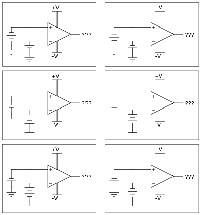
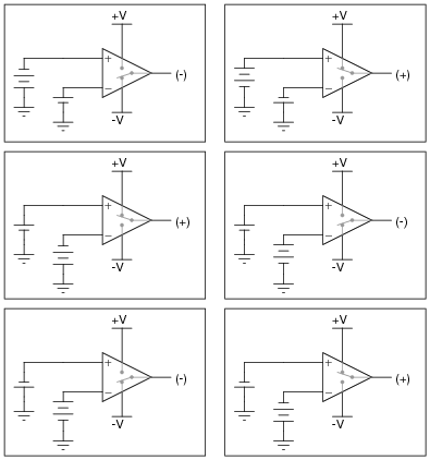
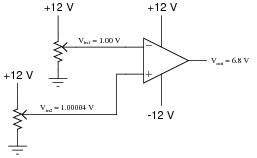
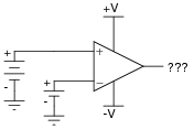
Determine the output voltage polarity of this op-amp (with reference to ground), given the following input conditions:
|
|
|
|
Notes:
Determining which "way" the output of an op-amp drives under different input voltage conditions is confusing to many students. Discuss this with them, and ask them to present any principles or analogies they use to remember "which way is which."
Question 2:
| Don't just sit there! Build something!! |
Learning to mathematically analyze circuits requires much study and practice. Typically, students practice by working through lots of sample problems and checking their answers against those provided by the textbook or the instructor. While this is good, there is a much better way.
You will learn much more by actually building and analyzing real circuits, letting your test equipment provide the änswers" instead of a book or another person. For successful circuit-building exercises, follow these steps:
- 1.
- Carefully measure and record all component values prior to circuit construction.
- 2.
- Draw the schematic diagram for the circuit to be analyzed.
- 3.
- Carefully build this circuit on a breadboard or other convenient medium.
- 4.
- Check the accuracy of the circuit's construction, following each wire to each connection point, and verifying these elements one-by-one on the diagram.
- 5.
- Mathematically analyze the circuit, solving for all voltage and current values.
- 6.
- Carefully measure all voltages and currents, to verify the accuracy of your analysis.
- 7.
- If there are any substantial errors (greater than a few percent), carefully check your circuit's construction against the diagram, then carefully re-calculate the values and re-measure.
Avoid using the model 741 op-amp, unless you want to challenge your circuit design skills. There are more versatile op-amp models commonly available for the beginner. I recommend the LM324 for DC and low-frequency AC circuits, and the TL082 for AC projects involving audio or higher frequencies.
As usual, avoid very high and very low resistor values, to avoid measurement errors caused by meter "loading". I recommend resistor values between 1 kW and 100 kW.
One way you can save time and reduce the possibility of error is to begin with a very simple circuit and incrementally add components to increase its complexity after each analysis, rather than building a whole new circuit for each practice problem. Another time-saving technique is to re-use the same components in a variety of different circuit configurations. This way, you won't have to measure any component's value more than once.
Notes:
It has been my experience that students require much practice with circuit analysis to become proficient. To this end, instructors usually provide their students with lots of practice problems to work through, and provide answers for students to check their work against. While this approach makes students proficient in circuit theory, it fails to fully educate them.
Students don't just need mathematical practice. They also need real, hands-on practice building circuits and using test equipment. So, I suggest the following alternative approach: students should build their own "practice problems" with real components, and try to mathematically predict the various voltage and current values. This way, the mathematical theory "comes alive," and students gain practical proficiency they wouldn't gain merely by solving equations.
Another reason for following this method of practice is to teach students scientific method: the process of testing a hypothesis (in this case, mathematical predictions) by performing a real experiment. Students will also develop real troubleshooting skills as they occasionally make circuit construction errors.
Spend a few moments of time with your class to review some of the "rules" for building circuits before they begin. Discuss these issues with your students in the same Socratic manner you would normally discuss the worksheet questions, rather than simply telling them what they should and should not do. I never cease to be amazed at how poorly students grasp instructions when presented in a typical lecture (instructor monologue) format!
A note to those instructors who may complain about the "wasted" time required to have students build real circuits instead of just mathematically analyzing theoretical circuits:
What is the purpose of students taking your course?
If your students will be working with real circuits, then they should learn on real circuits whenever possible. If your goal is to educate theoretical physicists, then stick with abstract analysis, by all means! But most of us plan for our students to do something in the real world with the education we give them. The "wasted" time spent building real circuits will pay huge dividends when it comes time for them to apply their knowledge to practical problems.
Furthermore, having students build their own practice problems teaches them how to perform primary research, thus empowering them to continue their electrical/electronics education autonomously.
In most sciences, realistic experiments are much more difficult and expensive to set up than electrical circuits. Nuclear physics, biology, geology, and chemistry professors would just love to be able to have their students apply advanced mathematics to real experiments posing no safety hazard and costing less than a textbook. They can't, but you can. Exploit the convenience inherent to your science, and get those students of yours practicing their math on lots of real circuits!
Question 3:
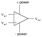
An operational amplifier is a particular type of differential amplifier. Most op-amps receive two input voltage signals and output one voltage signal:
|
|
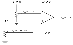
Here is a single op-amp, shown under two different conditions (different input voltages). Determine the voltage gain of this op-amp, given the conditions shown:
|
|
|
|
Also, write a mathematical formula solving for differential voltage gain (AV) in terms of an op-amp's input and output voltages.
|
Follow-up question: convert this voltage gain figure (as a ratio) into a voltage gain figure in decibels.
Notes:
The calculations for voltage gain here are not that different from the voltage gain calculations for any other amplifier, except that here we're dealing with a differential amplifier instead of a single-ended amplifier.
A differential voltage gain of 530,000 is not unreasonable for a modern operational amplifier! A gain so extreme may come as a surprise to many students, but they will discover later the utility of such a high gain.
Question 4:
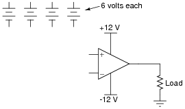
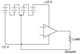
Many op-amp circuits require a dual or split power supply, consisting of three power terminals: +V, -V, and Ground. Draw the necessary connections between the 6-volt batteries in this schematic diagram to provide +12 V, -12 V, and Ground to this op-amp:
|
|
|
|
Notes:
I encourage your students to learn how to power op-amp circuits with interconnected batteries, because it really helps to build their understanding of what a ßplit" power supply is, as well as allow them to build functioning op-amp circuits in the absence of a quality benchtop power supply.
Question 5:
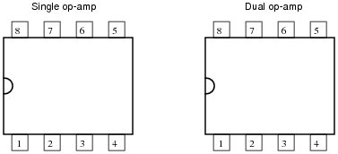
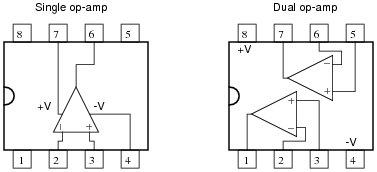
The 8-pin Dual-Inline-Package (DIP) is a common format in which single and dual operational amplifiers are housed. Shown here are the case outlines for two 8-pin DIPs. Draw the internal op-amp connections for a single op-amp unit, and for a dual op-amp unit:
|
|
You will need to research some op-amp datasheets to find this information. Examples of single op-amp chips include the LM741, CA3130, and TL081. Examples of dual op-amp chips include the LM1458 and TL082.
|
|
Notes:
Ask your students to reveal their information sources, and what specific models of op-amp they researched.
Question 6:
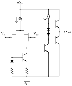
Shown here is a simplified schematic diagram of one of the operational amplifiers inside a TL08x (TL081, TL082, or TL084) op-amp integrated circuit:
|
|
Qualitatively determine what will happen to the output voltage (Vout) if the voltage on the noninverting input (Vin+) increases, and the voltage on the inverting input (Vin-) remains the same (all voltages are positive quantities, referenced to -V). Explain what happens at every stage of the op-amp circuit (voltages increasing or decreasing, currents increasing or decreasing) with this change in input voltage.
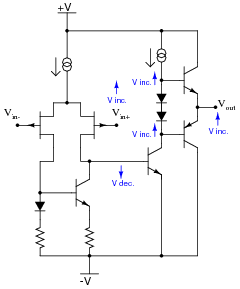
|
|
Notes:
The answer provided here is minimal. Challenge your students to follow the whole circuit through until the end, qualitatively assessing voltage and current changes.
Incidentally, the strange-looking double-circle symbol is a current source. Ask your students if they were able to find a reference anywhere describing what this symbol means.
Question 7:
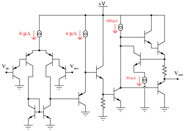
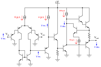
Shown here is a simplified schematic diagram of one of the operational amplifiers inside an LM324 quad op-amp integrated circuit:
|
|
Qualitatively determine what will happen to the output voltage (Vout) if the voltage on the inverting input (Vin-) increases, and the voltage on the noninverting input (Vin+) remains the same (all voltages are positive quantities, referenced to ground). Explain what happens at every stage of the op-amp circuit (voltages increasing or decreasing, currents increasing or decreasing) with this change in input voltage.
|
|
Notes:
The answer provided here is minimal. Challenge your students to follow the whole circuit through until the end, qualitatively assessing voltage and current changes.
Incidentally, the strange-looking double-circle symbol is a current source. Ask your students if they were able to find a reference anywhere describing what this symbol means.
Question 8:
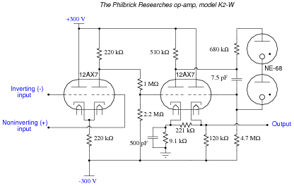
One of the first popular operational amplifiers was manufactured by Philbrick Researches, and it was called the K2-W. Built with two dual-triode vacuum tubes, its original schematic diagram looked like this:
|
|
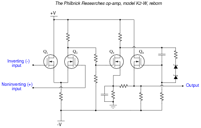
To make this opamp circuit easier for modern students to understand, I'll substitute equivalent solid-state components for all tubes in the original design:
|
|
Explain the configuration (common-source, common-drain, or common-gate) of each transistor in the modernized schematic, identifying the function of each in the operational amplifier circuit.
Notes:
The answer as given is incomplete. One could elaborate more on the function of each transistor, and by doing so understand the original amplifier circuit a little better. Explore this circuit with your students, challenging them to follow through the logic of the design, trying to figure out what the designer(s) intended.
This question also provides the opportunity to draw parallels between D-type MOSFET operation and the behavior of triode-type vacuum tubes. As with D-type MOSFETs, triodes were "normally half-on" devices, whose plate-cathode current conduction could be enhanced or depleted by applying voltage to the grid (with respect to the cathode).
Question 9:
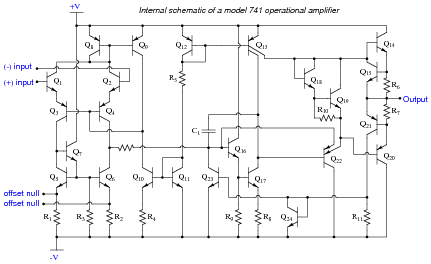
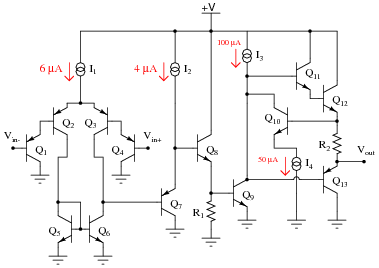
Determine the functions for as many components as you can in the following schematic diagram of a model 741 operational amplifier:
|
|
Notes:
Although the model 741 operational amplifier is considered obsolete by many modern standards, it is still a suitable circuit for this kind of exploration with students. Being able to look over a schematic diagram and figure out what the components do is an important troubleshooting skill. The fact that human circuit designers tend to repeat specific circuit elements and "modules" (such as the common-collector amplifier or the current mirror) in their designs rather than invent something completely novel for each design simplifies the task of later interpretation.
Question 10:
Predict how the operation of this operational amplifier circuit will be affected as a result of the following faults. Specifically, identify whether the output voltage (Vout) will move in a positive direction (closer to the +V rail) or in a negative direction (closer to ground). Consider each fault independently (i.e. one at a time, no multiple faults):
|
|
- �
- Transistor Q5 fails shorted (collector-to-emitter):
- �
- Transistor Q6 fails shorted (collector-to-emitter):
- �
- Resistor R1 fails open:
- �
- Current source I2 fails shorted:
For each of these conditions, explain why the resulting effects will occur.
- �
- Transistor Q5 fails shorted (collector-to-emitter): Vout goes negative.
- �
- Transistor Q6 fails shorted (collector-to-emitter): Vout goes positive.
- �
- Resistor R1 fails open: Vout goes negative.
- �
- Current source I2 fails shorted: Vout goes negative.
Notes:
The purpose of this question is to approach the domain of circuit troubleshooting from a perspective of knowing what the fault is, rather than only knowing what the symptoms are. Although this is not necessarily a realistic perspective, it helps students build the foundational knowledge necessary to diagnose a faulted circuit from empirical data. Questions such as this should be followed (eventually) by other questions asking students to identify likely faults based on measurements.
Question 11:
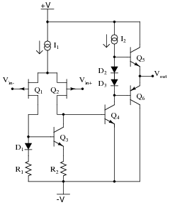
Predict how the operation of this operational amplifier circuit will be affected as a result of the following faults. Specifically, identify whether the output voltage (Vout) will move in a positive direction (closer to the +V rail) or in a negative direction (closer to the -V rail). Consider each fault independently (i.e. one at a time, no multiple faults):
|
|
- �
- Diode D1 fails open:
- �
- Resistor R1 fails shorted:
- �
- Transistor Q2 fails shorted (drain-to-source):
- �
- Transistor Q5 fails shorted (collector-to-emitter):
- �
- Resistor R2 fails open:
- �
- Current source I2 fails open:
For each of these conditions, explain why the resulting effects will occur.
- �
- Diode D1 fails open: Vout goes positive.
- �
- Resistor R1 fails shorted: Vout goes negative.
- �
- Transistor Q2 fails shorted (drain-to-source): Vout goes negative.
- �
- Transistor Q5 fails shorted (collector-to-emitter): Vout goes positive.
- �
- Resistor R2 fails open: Vout goes negative.
- �
- Current source I2 fails open: Vout goes negative.
Notes:
The purpose of this question is to approach the domain of circuit troubleshooting from a perspective of knowing what the fault is, rather than only knowing what the symptoms are. Although this is not necessarily a realistic perspective, it helps students build the foundational knowledge necessary to diagnose a faulted circuit from empirical data. Questions such as this should be followed (eventually) by other questions asking students to identify likely faults based on measurements.
Question 12:
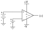
Ideally, what should the output voltage of an op-amp do if the noninverting voltage is greater (more positive) than the inverting voltage?
|
|
|
|
Notes:
Determining which "way" the output of an op-amp drives under different input voltage conditions is confusing to many students. Discuss this with them, and ask them to present any principles or analogies they use to remember "which way is which."
Question 13:
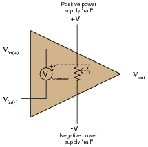
A helpful model for understanding opamp function is one where the output of an opamp is thought of as being the wiper of a potentiometer, the wiper position automatically adjusted according to the difference in voltage measured between the two inputs:
|
|
To elaborate further, imagine an extremely sensitive, analog, zero-center voltmeter inside the opamp, where the moving-coil mechanism of the voltmeter mechanically drives the potentiometer wiper. The wiper's position would then be proportional to both the magnitude and polarity of the difference in voltage between the two input terminals.
Realistically, building such a voltmeter/potentiometer mechanism with the same sensitivity and dynamic performance as a solid-state opamp circuit would be impossible, but the point here is to model the opamp in terms of components that we are already very familiar with, not to suggest an alternative construction for real opamps.
Describe how this model helps to explain the output voltage limits of an opamp, and also where the opamp sources or sinks load current from.
Follow-up question: does this model realistically depict the input characteristics (especially input impedance) of an opamp? Why or why not?
Notes:
Students have told me that this opamp model öpened their eyes" to the behavior of opamp outputs, especially in situations where they would have otherwise expected an opamp to deliver an output voltage exceeding one of the rail voltages, or where the path of load current was critical. One of the common fallacies new students have about opamps is that output current somehow originates from current at one or both of the input terminals. This model also helps to shatter that illusion.
As a new instructor, I used to be shocked to see such misunderstandings in my students' thinking. Surely from their previous experience with single-transistor amplifier circuits they knew the DC output voltage could never exceed the power supply rail voltages, right? Surely they understood that the current gain provided by multiple transistor stages effectively isolated output loading from the input(s), so that increased load at the output had negligible effect on input current, right? Well, not necessarily so!
The major reasons I am so adamant about having students expose their conceptions and thinking processes in a classroom discussion (rather than quietly listen to me lecture) is to be able to detect and correct these kinds of misunderstandings, and to be able to instill a sense of internal dialogue so that students learn to detect and correct the same kinds of misunderstandings on their own. Deep and critical thought does not seem to be a natural tendency in most human beings. To the contrary, a great many people seem perfectly content with meager and shallow comprehensions of the world around them, and must be prodded into assessing what they think they know. Pose questions to your students that challenge shallow thinking, that expose misunderstandings, and that force students to think more deeply than they are used to. In my opinion, building these metacognitive skills and habits is the very essence of higher education.
Question 14:
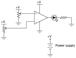
In this circuit, an op-amp turns on an LED if the proper input voltage conditions are met:
|
|
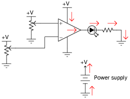
Trace the complete path of current powering the LED. Where, exactly, does the LED get its power from?
|
|
Notes:
The important thing to note here is that the load current does not pass through either of the op-amp's input terminals. All load current is sourced by the op-amp's power supply! Discuss the importance of this fact with your students.
Question 15:
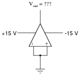
Ideally, when the two input terminals of an op-amp are shorted together (creating a condition of zero differential voltage), and those two inputs are connected directly to ground (creating a condition of zero common-mode voltage), what should this op-amp's output voltage be?
|
|
In reality, the output voltage of an op-amp under these conditions is not the same as what would be ideally predicted. Identify the fundamental problem in real op-amps, and also identify the best solution.
Follow-up question: the amount of differential voltage required to make the output of a real opamp settle at 0 volts is typically referred to as the input offset voltage. Research some typical input offset voltages for real operational amplifiers.
Challenge question: identify a model of op-amp that provides extra terminals for this "trimming" feature, and explain how it works.
Notes:
In many ways, real op-amps fall short of their ideal expectations. However, modern op-amps are far, far better than the first models manufactured. And with such a wide variety of models to choose from, it is possible to obtain an almost perfect match for whatever design application you have, for a modest price.
If possible, discuss how "trimming" works in a real op-amp. If your students took the "challenge" and found some op-amp datasheets describing how to implement trimming, have them relate the connection of external components to the op-amp's internal circuitry.
Question 16:
What does it mean if an operational amplifier has the ability to ßwing its output rail to rail"? Why is this an important feature to us?
Challenge question: identify at least one op-amp model that has this ability, and at least one that does not. Bring the datasheets for these op-amp models with you for reference during discussion time.
Notes:
Discuss what this feature means to us as circuit builders in a practical sense. Ask those students who tackled the challenge question to look up the output voltage ranges of their op-amp models. Exactly how close to +V and -V can the output voltage of an op-amp lacking "rail-to-rail" output capability ßwing"?
Question 17:
A very important parameter of operational amplifier performance is slew rate. Describe what ßlew rate" is, and why it is important for us to consider in choosing an op-amp for a particular application.
Notes:
Ask your students why [dv/dt] might be an important parameter in a circuit? In what application(s) might we need the op-amp to ßwing" its output voltage rapidly? In what application(s) might we not care about the op-amp's slew rate?
Question 18:
Some precision operational amplifiers are programmable. What does this feature mean? In what way can you "program" an op-amp?
Notes:
What possible benefits are there to "programming" the current source values in an operational amplifier? Discuss this with your students, asking them to share what they've found through their research.