Positive feedback opamp circuits
Question 1:
| Don't just sit there! Build something!! |
Learning to mathematically analyze circuits requires much study and practice. Typically, students practice by working through lots of sample problems and checking their answers against those provided by the textbook or the instructor. While this is good, there is a much better way.
You will learn much more by actually building and analyzing real circuits, letting your test equipment provide the änswers" instead of a book or another person. For successful circuit-building exercises, follow these steps:
- 1.
- Carefully measure and record all component values prior to circuit construction.
- 2.
- Draw the schematic diagram for the circuit to be analyzed.
- 3.
- Carefully build this circuit on a breadboard or other convenient medium.
- 4.
- Check the accuracy of the circuit's construction, following each wire to each connection point, and verifying these elements one-by-one on the diagram.
- 5.
- Mathematically analyze the circuit, solving for all voltage and current values.
- 6.
- Carefully measure all voltages and currents, to verify the accuracy of your analysis.
- 7.
- If there are any substantial errors (greater than a few percent), carefully check your circuit's construction against the diagram, then carefully re-calculate the values and re-measure.
Avoid using the model 741 op-amp, unless you want to challenge your circuit design skills. There are more versatile op-amp models commonly available for the beginner. I recommend the LM324 for DC and low-frequency AC circuits, and the TL082 for AC projects involving audio or higher frequencies.
As usual, avoid very high and very low resistor values, to avoid measurement errors caused by meter "loading". I recommend resistor values between 1 kW and 100 kW.
One way you can save time and reduce the possibility of error is to begin with a very simple circuit and incrementally add components to increase its complexity after each analysis, rather than building a whole new circuit for each practice problem. Another time-saving technique is to re-use the same components in a variety of different circuit configurations. This way, you won't have to measure any component's value more than once.
Notes:
It has been my experience that students require much practice with circuit analysis to become proficient. To this end, instructors usually provide their students with lots of practice problems to work through, and provide answers for students to check their work against. While this approach makes students proficient in circuit theory, it fails to fully educate them.
Students don't just need mathematical practice. They also need real, hands-on practice building circuits and using test equipment. So, I suggest the following alternative approach: students should build their own "practice problems" with real components, and try to mathematically predict the various voltage and current values. This way, the mathematical theory "comes alive," and students gain practical proficiency they wouldn't gain merely by solving equations.
Another reason for following this method of practice is to teach students scientific method: the process of testing a hypothesis (in this case, mathematical predictions) by performing a real experiment. Students will also develop real troubleshooting skills as they occasionally make circuit construction errors.
Spend a few moments of time with your class to review some of the "rules" for building circuits before they begin. Discuss these issues with your students in the same Socratic manner you would normally discuss the worksheet questions, rather than simply telling them what they should and should not do. I never cease to be amazed at how poorly students grasp instructions when presented in a typical lecture (instructor monologue) format!
A note to those instructors who may complain about the "wasted" time required to have students build real circuits instead of just mathematically analyzing theoretical circuits:
What is the purpose of students taking your course?
If your students will be working with real circuits, then they should learn on real circuits whenever possible. If your goal is to educate theoretical physicists, then stick with abstract analysis, by all means! But most of us plan for our students to do something in the real world with the education we give them. The "wasted" time spent building real circuits will pay huge dividends when it comes time for them to apply their knowledge to practical problems.
Furthermore, having students build their own practice problems teaches them how to perform primary research, thus empowering them to continue their electrical/electronics education autonomously.
In most sciences, realistic experiments are much more difficult and expensive to set up than electrical circuits. Nuclear physics, biology, geology, and chemistry professors would just love to be able to have their students apply advanced mathematics to real experiments posing no safety hazard and costing less than a textbook. They can't, but you can. Exploit the convenience inherent to your science, and get those students of yours practicing their math on lots of real circuits!
Question 2:
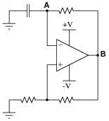
This is a very common opamp oscillator circuit, technically of the relaxation type:
|
|
Explain how this circuit works, and what waveforms will be measured at points A and B. Be sure to make reference to RC time constants in your explanation.
Challenge question: explain how you might go about calculating the frequency of such a circuit, based on what you know about RC time constant circuits. Assume that the opamp can swing its output rail-to-rail, for simplicity.
Notes:
This circuit is best understood by building and testing. If you use large capacitor values and/or a large-value resistor in the capacitor's current path, the oscillation will be slow enough to analyze with a voltmeter rather than an oscilloscope.
Question 3:
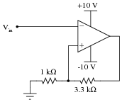
Assume that the comparator in this circuit is only capable of ßwinging" its output to within 1 volt of its power supply rail voltages. Calculate the upper and lower threshold voltages, given the resistor values shown:
|
|
VUT = VLT =
VLT = -2.093 volts
Notes:
As many opamps and comparators are incapable of rail-to-rail output swings, this question is quite realistic.
Question 4:
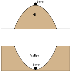
One analogy used to explain and contrast negative feedback versus positive feedback is that of a round stone, placed on either a hilltop or a valley:
|
|
The stability of the stone in each of these scenarios represents the stability of a specific type of electrical feedback system. Which of these scenarios represents negative feedback, which represents positive feedback, and why?
Notes:
I have found this simple analogy to be most helpful when explaining feedback systems to students, because the behavior of each is intuitively obvious.
Question 5:
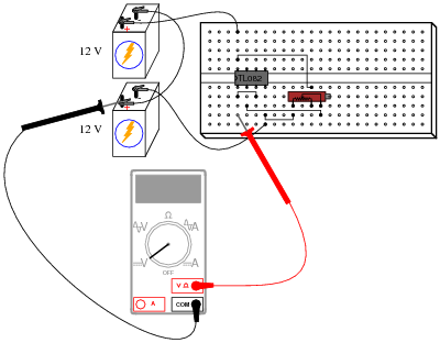
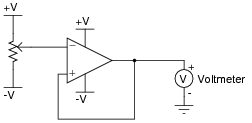
A student intends to connect a TL082 opamp as a voltage follower, to "follow" the voltage generated by a potentiometer, but makes a mistake in the breadboard wiring:
|
|
Draw a schematic diagram of this faulty circuit, and determine what the voltmeter's indication will be, explaining why it is such.
|
|
The output voltage will saturate at approximately +11 volts, or -11 volts, with the potentiometer having little or no effect.
Notes:
Ask your students to characterize the type of feedback exhibited in this circuit. How does this type of feedback affect the opamp's behavior? Is it possible for the opamp to function as a voltage follower, connected like this?
Question 6:
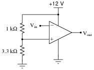
Determine the "trip" voltage of this comparator circuit: the value of input voltage at which the opamp's output changes state from fully positive to fully negative or visa-versa:
|
|
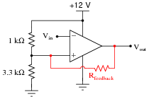
Now, what do you suppose would happen if the output were fed back to the noninverting input through a resistor? You answer merely has to be qualitative, not quantitative:
|
|
For your information, this circuit configuration is often referred to as a Schmitt trigger.
Follow-up question: describe what effect this changing "trip" voltage value will have on the operation of this comparator circuit.
Notes:
Schmitt trigger circuits are very popular for their ability to "cleanly" change states given a noisy input signal. I have intentionally avoided numerical calculations in this question, so that students may concentrate on the concept of positive feedback and how it affects this circuit.
Question 7:
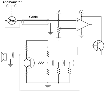
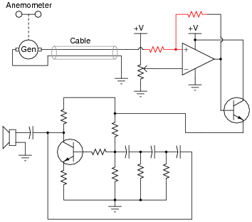
A comparator is used as a high wind speed alarm in this circuit, triggering an audio tone to sound whenever the wind speed exceeds a pre-set alarm point:
|
|
The circuit works well to warn of high wind speed, but when the wind speed is just near the threshold level, every little gust causes the alarm to briefly sound, then turn off again. What would be better is for the alarm to sound at a set wind speed, then stay on until the wind speed falls below a substantially lower threshold value (example: alarm at 60 km/h, reset at 50 km/h).
An experienced electronics technician decides to add this functionality to the circuit by adding two resistors:
|
|
Explain why this circuit alteration works to solve the problem.
Challenge question: suppose you wished to increase the gap between the upper and lower alarm thresholds. What resistor value(s) would you have to alter to accomplish this adjustment?
Notes:
A practical illustration for positive feedback in an opamp circuit. There is much to discuss here, even beyond the immediate context of positive feedback. Take for instance the oscillator circuit and on/off control transistor. For review, ask your students to explain how both these circuit sections function.
Question 8:
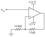
Assume that the comparator in this circuit is capable of ßwinging" its output fully from rail to rail. Calculate the upper and lower threshold voltages, given the resistor values shown:
|
|
VUT = VLT =
VLT = -8 volts
Challenge question: how would you recommend we change the circuit to give threshold voltages of +6 volts and -6 volts, respectively?
Notes:
Ask your students to explain what the terms üpper threshold" and "lower threshold" mean with regard to input voltage in a circuit such as this.
Question 9:
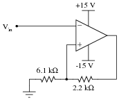
Assume that the comparator in this circuit is only capable of ßwinging" its output to within 1 volt of its power supply rail voltages. Calculate the upper and lower threshold voltages, given the resistor values shown:

|
|
VUT = VLT =
VLT = -4.087 volts
Notes:
As many opamps and comparators are incapable of rail-to-rail output swings, this question is quite realistic.
Question 10:
Assume that the comparator in this circuit is only capable of ßwinging" its output to within 1 volt of its power supply rail voltages. Calculate the upper and lower threshold voltages, given the resistor values shown:
|
|
VUT = VLT =
VLT = -10.29 volts
Challenge question: how would you recommend we change the circuit so that its threshold voltages are centered around some voltage value other than zero?
Notes:
As many opamps and comparators are incapable of rail-to-rail output swings, this question is quite realistic.
Question 11:
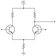
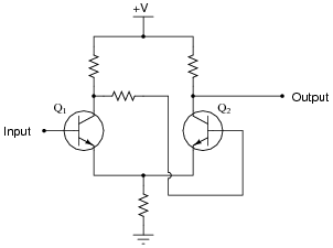
Comparators with positive feedback are sometimes referred to as Schmitt triggers. Suppose you needed a Schmitt trigger for a circuit you were building, but did not have any more integrated circuit comparators or op-amps to use. All you have available to you are discrete components. Is there any way you can think of to modify the following discrete transistor differential pair so that it behaves as a Schmitt trigger?
|
|
|
|
Notes:
Ask your students to determine whether this Schmitt trigger circuit is inverting or non-inverting. Have them explain their reasoning step-by-step.
Authors Paul Horowitz and Winfield Hill, in their book The Art of Electronics, say that Q1's collector resistor must be larger than Q2's collector resistor in order for this circuit to work properly (page 232, second edition).
Question 12:
Positive or regenerative feedback is an essential characteristic of all oscillator circuits. Why, then, do comparator circuits utilizing positive feedback not oscillate? Instead of oscillating, the output of a comparator circuit with positive feedback simply saturates to one of its two rail voltage values. Explain this.
Notes:
This is a challenging question, and may not be suitable for all students. Basically, what I'm trying to get students to do here is think carefully about the nature of positive feedback as used in comparator circuits, versus as it's used in oscillator circuits. Students who have simply memorized the concept of "positive feedback causing oscillation" will fail to understand what is being asked in this question, much less understand the given answer.