Summer and subtractor opamp circuits
Question 1:
| Don't just sit there! Build something!! |
Learning to mathematically analyze circuits requires much study and practice. Typically, students practice by working through lots of sample problems and checking their answers against those provided by the textbook or the instructor. While this is good, there is a much better way.
You will learn much more by actually building and analyzing real circuits, letting your test equipment provide the änswers" instead of a book or another person. For successful circuit-building exercises, follow these steps:
- 1.
- Carefully measure and record all component values prior to circuit construction.
- 2.
- Draw the schematic diagram for the circuit to be analyzed.
- 3.
- Carefully build this circuit on a breadboard or other convenient medium.
- 4.
- Check the accuracy of the circuit's construction, following each wire to each connection point, and verifying these elements one-by-one on the diagram.
- 5.
- Mathematically analyze the circuit, solving for all voltage and current values.
- 6.
- Carefully measure all voltages and currents, to verify the accuracy of your analysis.
- 7.
- If there are any substantial errors (greater than a few percent), carefully check your circuit's construction against the diagram, then carefully re-calculate the values and re-measure.
Avoid using the model 741 op-amp, unless you want to challenge your circuit design skills. There are more versatile op-amp models commonly available for the beginner. I recommend the LM324 for DC and low-frequency AC circuits, and the TL082 for AC projects involving audio or higher frequencies.
As usual, avoid very high and very low resistor values, to avoid measurement errors caused by meter "loading". I recommend resistor values between 1 kW and 100 kW.
One way you can save time and reduce the possibility of error is to begin with a very simple circuit and incrementally add components to increase its complexity after each analysis, rather than building a whole new circuit for each practice problem. Another time-saving technique is to re-use the same components in a variety of different circuit configurations. This way, you won't have to measure any component's value more than once.
Notes:
It has been my experience that students require much practice with circuit analysis to become proficient. To this end, instructors usually provide their students with lots of practice problems to work through, and provide answers for students to check their work against. While this approach makes students proficient in circuit theory, it fails to fully educate them.
Students don't just need mathematical practice. They also need real, hands-on practice building circuits and using test equipment. So, I suggest the following alternative approach: students should build their own "practice problems" with real components, and try to mathematically predict the various voltage and current values. This way, the mathematical theory "comes alive," and students gain practical proficiency they wouldn't gain merely by solving equations.
Another reason for following this method of practice is to teach students scientific method: the process of testing a hypothesis (in this case, mathematical predictions) by performing a real experiment. Students will also develop real troubleshooting skills as they occasionally make circuit construction errors.
Spend a few moments of time with your class to review some of the "rules" for building circuits before they begin. Discuss these issues with your students in the same Socratic manner you would normally discuss the worksheet questions, rather than simply telling them what they should and should not do. I never cease to be amazed at how poorly students grasp instructions when presented in a typical lecture (instructor monologue) format!
A note to those instructors who may complain about the "wasted" time required to have students build real circuits instead of just mathematically analyzing theoretical circuits:
What is the purpose of students taking your course?
If your students will be working with real circuits, then they should learn on real circuits whenever possible. If your goal is to educate theoretical physicists, then stick with abstract analysis, by all means! But most of us plan for our students to do something in the real world with the education we give them. The "wasted" time spent building real circuits will pay huge dividends when it comes time for them to apply their knowledge to practical problems.
Furthermore, having students build their own practice problems teaches them how to perform primary research, thus empowering them to continue their electrical/electronics education autonomously.
In most sciences, realistic experiments are much more difficult and expensive to set up than electrical circuits. Nuclear physics, biology, geology, and chemistry professors would just love to be able to have their students apply advanced mathematics to real experiments posing no safety hazard and costing less than a textbook. They can't, but you can. Exploit the convenience inherent to your science, and get those students of yours practicing their math on lots of real circuits!
Question 2:
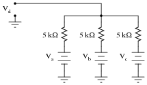
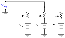
The simple resistor network shown here is known as a passive averager. Describe what the word "passive" means in this context, and write an equation describing the output voltage (Vd) in terms of the input voltages (Va, Vb, and Vc):
|
|
Hint: there is a network theorem that directly applies to this form of circuit, and it is known as Millman's Theorem. Research this theorem and use it to generate your equation!
|
Notes:
Students need to realize that even passive circuits are able to model (some) mathematical functions! Ask your students if they can think of any network analysis methods to easily calculate the output voltage (Vd) of this circuit, given the input voltages. There is one theorem in particular that works very well for this particular circuit.
Question 3:
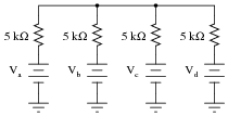
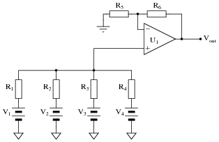
Add an op-amp circuit to the output of this passive averager network to produce a summer circuit: an operational circuit generating an output voltage equal to the sum of the four input voltages. Then, write an equation describing the whole circuit's function.
|
|
|
|
|
Notes:
The equation for this circuit is simple enough as to require no explanation. How your students derived this equation, from the base equation of a passive averager network, on the other hand, is worth discussion. Discuss with them the necessary gain of the op-amp circuit, and how this gain figure converts an averaging function into a summing function.
Question 4:
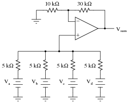
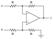
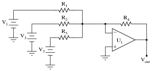
Write a mathematical equation for this op-amp circuit, assuming all resistor values are equal:
|
|
What is this circuit typically called?
This type of circuit is typically called an inverting summer.
Follow-up question: explain why the addition of another resistor in this circuit is recommended for optimum accuracy, as shown in the following schematic.
|
|
Challenge question: write an equation describing the proper value of this extra resistor.
Notes:
Ask your students about the proper resistor values for an inverting summer circuit. The choices of resistor values are definitely not the same for inverting summer and noninverting summer circuits alike! Discuss why the values are what they are in an inverting summer circuit (using Ohm's Law to analyze the circuit's function), emphasizing comprehension over rote memorization.
Question 5:
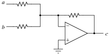
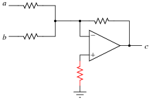
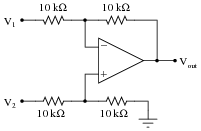
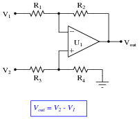
This opamp circuit is known as a difference amplifier, sometimes called a subtractor. Assuming that all resistor values are equal in the circuit, write an equation expressing the output (y) as a function of the two input voltages (a and b):
|
|
Notes:
Work through some example conditions of input voltages and resistor values to calculate the output voltage using Ohm's Law and the general principle of negative feedback in an opamp circuit (namely, an assumption of zero voltage differential at the opamp inputs). The goal here is to have students comprehend why this circuit subtracts one voltage from another, rather than just encourage rote memorization.
Question 6:
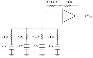
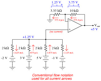
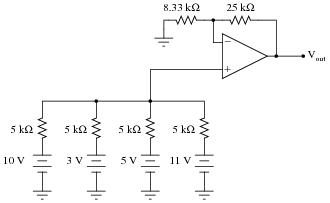
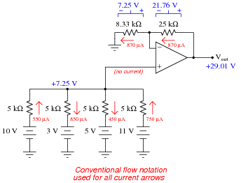
Determine all current magnitudes and directions, as well as voltage drops, in this circuit:
|
|
|
|
Follow-up question: what would be required to get this circuit to output the exact sum of the four input voltages?
Notes:
This question not only provides practice analyzing the behavior of a summer circuit, but also analyzing the behavior of a passive averager circuit. If your students need some refreshing on how to analyze the passive averager, you might want to review Millman's Theorem with them.
Question 7:
Determine all current magnitudes and directions, as well as voltage drops, in this circuit:
|
|
|
|
Follow-up question: what would be required to get this circuit to output the exact sum of the four input voltages?
Notes:
This question not only provides practice analyzing the behavior of a summer circuit, but also analyzing the behavior of a passive averager circuit. If your students need some refreshing on how to analyze the passive averager, you might want to review Millman's Theorem with them.
Question 8:
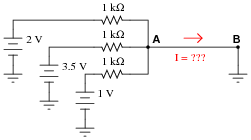
Determine the amount of current from point A to point B in this circuit:
|
|
Notes:
This question, while being an application of Kirchhoff's Current Law, is also a prelude to an inverting summer circuit, where an opamp takes that 6.5 mA (total) current and converts it into an output voltage.
Question 9:
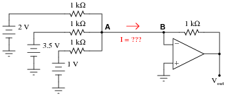
Determine the amount of current from point A to point B in this circuit, and also the output voltage of the operational amplifier:
|
|
Notes:
This question is best preceded by #02516, which asks for students to solve for the current between A and B with no opamp in the circuit (simply grounded at point B). When students realize that point B is now a virtual ground instead of a real ground, they see that the same conclusion derived by Kirchhoff's Current Law in the passive circuit is still valid in this active circuit, and that the result is an output voltage corresponding to that current.
Question 10:
Identify some of the distinguishing characteristics of inverting and noninverting summer circuits. How may you identify which is which, and how may you determine the proper resistor values to make each one work as it should?
Notes:
This question is designed to spur discussion amongst your students, exchanging ideas about each circuit's defining characteristics. Having students explore each circuit type on their own, reaching their own conclusions about how to differentiate the two, is a far more effective way of making them understand the differences than simply telling them outright.
Question 11:
Complete the table of values for this opamp circuit, calculating the output voltage for each combination of input voltages shown:
|
|
-
V1 V2 Vout
0 V 0 V
+1 V 0 V
0 V +1 V
+2 V +1.5 V
+3.4 V +1.2 V
-2 V +4 V
+5 V +5 V
-3 V -3 V
What pattern do you notice in the data? What mathematical relationship is there between the two input voltages and the output voltage?
-
V1 V2 Vout
0 V 0 V 0 V
+1 V 0 V -1 V
0 V +1 V +1 V
+2 V +1.5 V -0.5 V
+3.4 V +1.2 V -2.2 V
-2 V +4 V +6 V
+5 V +5 V 0 V
-3 V -3 V 0 V
Notes:
Thought it may be tedious to calculate the output voltage for each set of input voltages, working through all the voltage drops and currents in the opamp circuit one at a time, it shows students how they may be able to discern the function of an opamp circuit merely by applying basic laws of electricity (Ohm's Law, KVL, and KCL) and the "golden assumptions" of negative feedback opamp circuits (no input currents, zero differential input voltage).
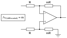
Question 12:
How does the operation of this difference amplifier circuit compare with the resistor values given (2R = twice the resistance of R), versus its operation with all resistor values equal?
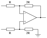
|
|
Describe what approach or technique you used to derive your answer, and also explain how your conclusion for this circuit might be generalized for all difference amplifier circuits.
As for a generalized conclusion:
|
|
Notes:
It is easy for you (the instructor) to show how and why this circuit acts as it does. The point of this question, however, is to get students to take the initiative to explore the circuit on their own. It is simple enough for any student to set up some hypothetical test conditions (a thought experiment) to analyze what this circuit will do, that the only thing holding them back from doing so is attitude, not aptitude.
This is something I have noticed over years of teaching: so many students who are more than capable of doing the math and applying well-understood electrical rules refuse to do so on their own, because years of educational tradition has indoctrinated them to wait for the instructor's lead rather than explore a concept on their own.
Question 13:
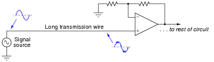
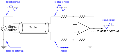
If a weak voltage signal is conveyed from a source to an amplifier, the amplifier may detect more than just the desired signal. Along with the desired signal, external electronic "noise" may be coupled to the transmission wire from AC sources such as power line conductors, radio waves, and other electromagnetic interference sources. Note the two waveshapes, representing voltages along the transmission wire measured with reference to earth ground:
|
|
Shielding of the transmission wire is always a good idea in electrically noisy environments, but there is a more elegant solution than simply trying to shield interference from getting to the wire. Instead of using a single-ended amplifier to receive the signal, we can transmit the signal along two wires and use a difference amplifier at the receiving end. Note the four waveforms shown, representing voltages at those points measured with reference to earth ground:
|
|
If the two wires are run parallel to each other the whole distance, so as to be exposed to the exact same noise sources along that distance, the noise voltage at the end of the bottom wire will be the same noise voltage as that superimposed on the signal at the end of the top wire.
Explain how the difference amplifier is able to restore the original (clean) signal voltage from the two noise-ridden voltages seen at its inputs with respect to ground, and also how the phrase common-mode voltage applies to this scenario.
Challenge question: re-draw the original (one wire plus ground) schematic to model the sources of interference and the wire's impedance, to show exactly how the signal could become mixed with noise from source to amplifier.
Notes:
Differential signal transmission is a very practical application of difference amplifiers, and forms the foundation of certain data transmission standard physical layers such as RS-422 and RS-485.
Question 14:
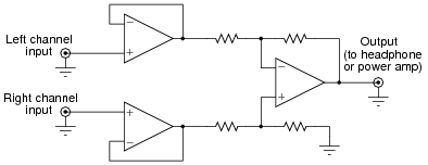
Singers who wish to practice singing to popular music find that the following vocal eliminator circuit is useful:
|
|
The circuit works on the principle that vocal tracks are usually recorded through a single microphone at the recording studio, and thus are represented equally on each channel of a stereo sound system. This circuit effectively eliminates the vocal track from the song, leaving only the music to be heard through the headphone or speaker.
Explain how the operational amplifiers accomplish this task of vocal track elimination. What role does each opamp play in this circuit?
Challenge question: unfortunately, the circuit as shown tends to eliminate bass tones as well as vocals, since the acoustic properties of bass tones make them represented nearly equally on both channels. Determine how the circuit may be expanded to include opamps that re-introduce bass tones to the "vocal-eliminated" output.
Notes:
Circuits like this are great for illustration, because they show practical application of a principle while engaging student interest.
One of my students, when faced with the challenge question, suggested placing a high-pass filter before one of the subtractor's inputs, eliminating bass tones at one of the inputs and therefore reproducing bass tones at the subtractor output. This is a great idea, and shows what can happen when students are given a forum to think creatively and freely express ideas, but there are some practical reasons it would be difficult to implement. The concept works great if we assume the use of a perfect HP filter, with absolutely zero phase shift and zero attenuation through the entire pass-band. Unfortunately, real filter circuits always exhibit some degree of both, and so the process of subtraction would not be as effective as necessary to eliminate the vocals from a song.
Question 15:
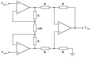
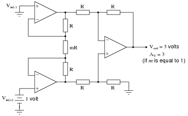
The following circuit is known as an instrumentation amplifier:
|
|
Suppose a DC voltage were to be applied to the noninverting input terminal, +1 volt at Vin(+), and the inverting input terminal grounded. Complete the following table showing the output voltage of this circuit for different values of m:
-
m Vout
1
2
3
4
5
6
-
m Vout
1 3 volts
2 2 volts
3 1.66 volts
4 1.5 volts
5 1.4 volts
6 1.33 volts
|
Follow-up question: why did I choose to set the noninverting input voltage at +1 volts and ground the inverting input? Should we not be able to calculate gain given any two input voltages and a value for m? Explain the purpose behind my choice of input voltage conditions for this "thought experiment."
Notes:
While the relationship between instrumentation amplifier differential gain and m may be looked up in any good opamp circuit textbook, it is something that your students should learn to figure out on their own from the data in the table.
Question 16:
Find the datasheet for a real instrumentation amplifier (packaged as a single integrated circuit) and bring it to class for discussion with your classmates. Analyze and discuss the inner workings of the circuit, and some of its performance parameters. If you do not know where to begin looking, try researching the Analog Devices model AD623, either in a reference book or on the internet.
Notes:
The idea of this question is to get students researching real integrated circuit applications, to teach them how to do this research and also how to interpret what they find. Since there are so many high-quality instrumentation amplifiers already built and packaged as monolithic units, it is usually not worth the technician's time to fabricate one from individual opamps. However, when specifying a pre-built instrumentation amplifier, it is essential to know what you need and how to use it once it arrives!
Question 17:
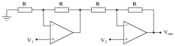
The following circuit is a type of difference amplifier, similar in behavior to the instrumentation amplifier, but only using two operational amplifiers instead of three:
|
|
Complete the table of values for this opamp circuit, calculating the output voltage for each combination of input voltages shown. From the calculated values of output voltage, determine which input of this circuit is inverting, and which is noninverting, and also how much differential voltage gain this circuit has. Express these conclusions in the form of an equation.
-
V1 V2 Vout
0 V 0 V
+1 V 0 V
0 V +1 V
+2 V +1.5 V
+3.4 V +1.2 V
-2 V +4 V
+5 V +5 V
-3 V -3 V
-
V1 V2 Vout
0 V 0 V 0 V
+1 V 0 V -2 V
0 V +1 V +2 V
+2 V +1.5 V -1 V
+3.4 V +1.2 V -4.4 V
-2 V +4 V +12 V
+5 V +5 V 0 V
-3 V -3 V 0 V
|
Follow-up question: explain how this circuit is at once similar and different from the popular ïnstrumentation amplifier" circuit.
Notes:
Although it would be easy enough just to tell students which input is inverting and which input is noninverting, they will learn more (and practice their analysis skills more) if asked to work through the table of values to figure it out.
Question 18:
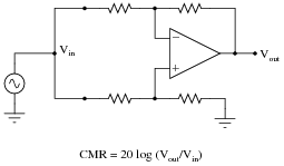
An important parameter of any differential amplifier - bare opamps and difference amplifiers made from opamps alike - is common-mode rejection, or CMR. Explain what this parameter means, how the following circuit tests this parameter, and why it is important to us:
|
|
Follow-up question: what range of CMR values would you expect from a good differential amplifier, if subjected to the test shown in the schematic and CMR calculated by the given formula?
Notes:
In case some students do not recall (!), the logarithmic formula is nothing special. It simply provides an answer in units of decibels.
Question 19:
Explain what common-mode rejection ratio means for a differential amplifier, and give a formula for calculating it.
|
The fundamental mechanism causing a common-mode signal to make it through to the output of a differential amplifier is a change in input offset voltage resulting from shifts in bias caused by that common-mode voltage. So, sometimes you may see CMRR defined as such:
|
Notes:
An application that really shows the value of a high CMRR is differential signal transmission, as shown in question #02519. For those students not grasping the significance of CMRR, this would be a good example circuit to show them.
Question 20:
Predict how the operation of this passive averager network will be affected as a result of the following faults. Consider each fault independently (i.e. one at a time, no multiple faults):
|
|
- �
- Resistor R1 fails open:
- �
- Solder bridge (short) across resistor R1:
- �
- Resistor R2 fails open:
- �
- Solder bridge (short) across resistor R2:
- �
- Resistor R3 fails open:
- �
- Solder bridge (short) across resistor R3:
For each of these conditions, explain why the resulting effects will occur.
- �
- Resistor R1 fails open: Vavg becomes the average of V2 and V3 only.
- �
- Solder bridge (short) across resistor R1: Vavg becomes exactly equal to V1.
- �
- Resistor R2 fails open: Vavg becomes the average of V1 and V3 only.
- �
- Solder bridge (short) across resistor R2: Vavg becomes exactly equal to V2.
- �
- Resistor R3 fails open: Vavg becomes the average of V1 and V2 only.
- �
- Solder bridge (short) across resistor R3: Vavg becomes exactly equal to V3.
Notes:
The purpose of this question is to approach the domain of circuit troubleshooting from a perspective of knowing what the fault is, rather than only knowing what the symptoms are. Although this is not necessarily a realistic perspective, it helps students build the foundational knowledge necessary to diagnose a faulted circuit from empirical data. Questions such as this should be followed (eventually) by other questions asking students to identify likely faults based on measurements.
Question 21:
Predict how the operation of this summer circuit will be affected as a result of the following faults. Consider each fault independently (i.e. one at a time, no multiple faults):
|
|
- �
- Resistor R1 fails open:
- �
- Solder bridge (short) across resistor R3:
- �
- Resistor R4 fails open:
- �
- Resistor R5 fails open:
- �
- Solder bridge (short) across resistor R5:
- �
- Resistor R6 fails open:
For each of these conditions, explain why the resulting effects will occur.
- �
- Resistor R1 fails open: Vout becomes equal to 4/3 the sum of voltages V2, V3, and V4.
- �
- Solder bridge (short) across resistor R3: Vout becomes equal to 4 times V3.
- �
- Resistor R4 fails open: Vout becomes equal to 4/3 the sum of voltages V1, V2, and V3.
- �
- Resistor R5 fails open: Circuit operates as an averager, not a summer.
- �
- Solder bridge (short) across resistor R5: Vout saturates in a positive direction.
- �
- Resistor R6 fails open: Vout saturates in a positive direction.
Notes:
The purpose of this question is to approach the domain of circuit troubleshooting from a perspective of knowing what the fault is, rather than only knowing what the symptoms are. Although this is not necessarily a realistic perspective, it helps students build the foundational knowledge necessary to diagnose a faulted circuit from empirical data. Questions such as this should be followed (eventually) by other questions asking students to identify likely faults based on measurements.
Question 22:
Predict how the operation of this summer circuit will be affected as a result of the following faults. Consider each fault independently (i.e. one at a time, no multiple faults):
|
|
- �
- Resistor R1 fails open:
- �
- Resistor R2 fails open:
- �
- Solder bridge (short) across resistor R3:
- �
- Resistor R4 fails open:
- �
- Solder bridge (short) across resistor R4:
For each of these conditions, explain why the resulting effects will occur.
- �
- Resistor R1 fails open: Vout becomes (inverted) sum of V2 and V3 only.
- �
- Resistor R2 fails open: Vout becomes (inverted) sum of V1 and V3 only.
- �
- Solder bridge (short) across resistor R3: Vout saturates in a negative direction.
- �
- Resistor R4 fails open: Vout saturates in a negative direction.
- �
- Solder bridge (short) across resistor R4: Vout goes to 0 volts.
Notes:
The purpose of this question is to approach the domain of circuit troubleshooting from a perspective of knowing what the fault is, rather than only knowing what the symptoms are. Although this is not necessarily a realistic perspective, it helps students build the foundational knowledge necessary to diagnose a faulted circuit from empirical data. Questions such as this should be followed (eventually) by other questions asking students to identify likely faults based on measurements.
Question 23:
Predict how the operation of this difference amplifier circuit will be affected as a result of the following faults. Consider each fault independently (i.e. one at a time, no multiple faults):
|
|
- �
- Resistor R1 fails open:
- �
- Resistor R2 fails open:
- �
- Solder bridge (short) across resistor R3:
- �
- Resistor R4 fails open:
- �
- Solder bridge (short) across resistor R4:
For each of these conditions, explain why the resulting effects will occur.
- �
- Resistor R1 fails open: Vout becomes equal to 1/2 V2.
- �
- Resistor R2 fails open: Vout saturates.
- �
- Solder bridge (short) across resistor R3: Vout becomes equal to 2 V2 - V1 instead of V2 - V1.
- �
- Resistor R4 fails open: Vout becomes equal to 2 V2 - V1 instead of V2 - V1.
- �
- Solder bridge (short) across resistor R4: Vout becomes equal to -V1.
Notes:
The purpose of this question is to approach the domain of circuit troubleshooting from a perspective of knowing what the fault is, rather than only knowing what the symptoms are. Although this is not necessarily a realistic perspective, it helps students build the foundational knowledge necessary to diagnose a faulted circuit from empirical data. Questions such as this should be followed (eventually) by other questions asking students to identify likely faults based on measurements.
Question 24:
The instrumentation amplifier is a popular circuit configuration for analog signal conditioning in a wide variety of electronic measurement applications. One of the reasons it is so popular is that its differential gain may be set by changing the value of a single resistor, the value of which is represented in this schematic by a multiplier constant named m:

|
|
There is an equation describing the differential gain of an instrumentation amplifier, but it is easy enough to research so I'll leave that detail up to you. What I'd like you to do here is algebraically derive that equation based on what you know of inverting and noninverting operational amplifier circuits.
Suppose we apply +1 volt to the noninverting input and ground the inverting input, giving a differential input voltage of 1 volt. Whatever voltage appears at the output of the instrumentation amplifier circuit, then, directly represents the voltage gain:
|
|
A hint for constructing an algebraic explanation for the circuit's output voltage is to view the two "buffer" opamps separately, as inverting and noninverting amplifiers:
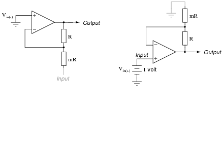
|
|
Note which configuration (inverting or noninverting) each of these circuits resemble, develop transfer functions for each (Output = � Input), then combine the two equations in a manner representing what the subtractor circuit will do. Your final result should be the gain equation for an instrumentation amplifier in terms of m.
Equation for inverting side:
|
Equation for noninverting side:
|
Notes:
This question actually originated from one of my students as he tried to figure out an algebraic explanation for the instrumentation amplifier's gain! I thought the idea was so good that I decided to include it as a question in the Socratic Electronics project.
Astute students will note that the negative sign in the inverting amplifier equation becomes very important in this proof. As an instructor, I often avoid signs, choosing to figure out the polarity of the signal as a final step after all the other arithmetic has been completed for a circuit analysis. As such, I usually present the inverting amplifier equation as [(Rf)/(Rin)] with the caveat of inverted polarity from input to output. Here, though, the negative sign becomes a vital part of the solution!
Question 25:
Calculate the voltage gain of the following opamp circuit with the potentiometer turned fully up, precisely mid-position, and fully down:
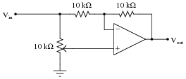
|
|
- �
- AV (pot fully up) =
- �
- AV (pot mid-position) =
- �
- AV (pot fully down) =
- �
- AV (pot fully up) = +1
- �
- AV (pot mid-position) = 0
- �
- AV (pot fully down) = -1
Follow-up question: can you think of any interesting applications for a circuit such as this?
Challenge question: modify the circuit so that the range of voltage gain adjustment is -6 to +6 instead of -1 to +1.
Notes:
Ask your students how they approached this problem. How, exactly, did they choose to set it up so the solution became most apparent?