Voltage/current converter opamp circuits
Question 1:
| Don't just sit there! Build something!! |
Learning to mathematically analyze circuits requires much study and practice. Typically, students practice by working through lots of sample problems and checking their answers against those provided by the textbook or the instructor. While this is good, there is a much better way.
You will learn much more by actually building and analyzing real circuits, letting your test equipment provide the änswers" instead of a book or another person. For successful circuit-building exercises, follow these steps:
- 1.
- Carefully measure and record all component values prior to circuit construction.
- 2.
- Draw the schematic diagram for the circuit to be analyzed.
- 3.
- Carefully build this circuit on a breadboard or other convenient medium.
- 4.
- Check the accuracy of the circuit's construction, following each wire to each connection point, and verifying these elements one-by-one on the diagram.
- 5.
- Mathematically analyze the circuit, solving for all voltage and current values.
- 6.
- Carefully measure all voltages and currents, to verify the accuracy of your analysis.
- 7.
- If there are any substantial errors (greater than a few percent), carefully check your circuit's construction against the diagram, then carefully re-calculate the values and re-measure.
Avoid using the model 741 op-amp, unless you want to challenge your circuit design skills. There are more versatile op-amp models commonly available for the beginner. I recommend the LM324 for DC and low-frequency AC circuits, and the TL082 for AC projects involving audio or higher frequencies.
As usual, avoid very high and very low resistor values, to avoid measurement errors caused by meter "loading". I recommend resistor values between 1 kW and 100 kW.
One way you can save time and reduce the possibility of error is to begin with a very simple circuit and incrementally add components to increase its complexity after each analysis, rather than building a whole new circuit for each practice problem. Another time-saving technique is to re-use the same components in a variety of different circuit configurations. This way, you won't have to measure any component's value more than once.
Notes:
It has been my experience that students require much practice with circuit analysis to become proficient. To this end, instructors usually provide their students with lots of practice problems to work through, and provide answers for students to check their work against. While this approach makes students proficient in circuit theory, it fails to fully educate them.
Students don't just need mathematical practice. They also need real, hands-on practice building circuits and using test equipment. So, I suggest the following alternative approach: students should build their own "practice problems" with real components, and try to mathematically predict the various voltage and current values. This way, the mathematical theory "comes alive," and students gain practical proficiency they wouldn't gain merely by solving equations.
Another reason for following this method of practice is to teach students scientific method: the process of testing a hypothesis (in this case, mathematical predictions) by performing a real experiment. Students will also develop real troubleshooting skills as they occasionally make circuit construction errors.
Spend a few moments of time with your class to review some of the "rules" for building circuits before they begin. Discuss these issues with your students in the same Socratic manner you would normally discuss the worksheet questions, rather than simply telling them what they should and should not do. I never cease to be amazed at how poorly students grasp instructions when presented in a typical lecture (instructor monologue) format!
A note to those instructors who may complain about the "wasted" time required to have students build real circuits instead of just mathematically analyzing theoretical circuits:
What is the purpose of students taking your course?
If your students will be working with real circuits, then they should learn on real circuits whenever possible. If your goal is to educate theoretical physicists, then stick with abstract analysis, by all means! But most of us plan for our students to do something in the real world with the education we give them. The "wasted" time spent building real circuits will pay huge dividends when it comes time for them to apply their knowledge to practical problems.
Furthermore, having students build their own practice problems teaches them how to perform primary research, thus empowering them to continue their electrical/electronics education autonomously.
In most sciences, realistic experiments are much more difficult and expensive to set up than electrical circuits. Nuclear physics, biology, geology, and chemistry professors would just love to be able to have their students apply advanced mathematics to real experiments posing no safety hazard and costing less than a textbook. They can't, but you can. Exploit the convenience inherent to your science, and get those students of yours practicing their math on lots of real circuits!
Question 2:
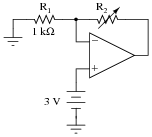
Calculate the current through resistor R2 in this opamp circuit for several different values of R2:
|
|
-
R2 IR2
1 kW
2 kW
3 kW
4 kW
5 kW
6 kW
For each value of R2, what is it that establishes the amount of current through it? Do you see any practical value for a circuit such as this?
-
R2 IR2
1 kW 3 mA
2 kW 3 mA
3 kW 3 mA
4 kW 3 mA
5 kW 3 mA
6 kW 3 mA
This circuit acts like a current mirror, except much more precise.
Follow-up question: what factor(s) limit the greatest resistance value of R2 that the operational amplifier may sustain 3 milliamps of current through?
Notes:
Besides reviewing the purpose of a current mirror circuit, this question draws students' attention to the current-regulating capabilities of an operational amplifier by having them analyze it as though it were simply a noninverting voltage amplifier circuit.
Question 3:
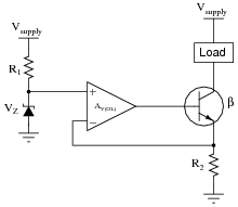
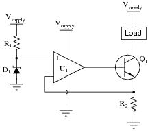
Explain how the operational amplifier maintains a constant current through the load:
|
|
Write an equation solving for the regulated load current, given any relevant variables shown in the schematic diagram (R1, VZ, Vsupply, AV(OL), etc.).
|
Follow-up question: is the transistor sourcing current to the load, or sinking current from it?
Challenge question #1: modify the given equation to more precisely predict load current, taking the b of the transistor into account.
Challenge question #2: modify the location of the load in this circuit so that the given equation does precisely predict load current, rather than closely approximate load current.
Notes:
This is a good example of how operational amplifiers may greatly improve the functions of discrete-component circuits. In this case, the opamp performs the function of a current mirror circuit, and does so with greater precision and reliability than a simple current mirror ever could.
It should be noted that the equation provided in the answer does not directly predict the current through the load, rather it predicts current through resistor R2. This is equal to load current only if the transistor's base current is zero, which of course it cannot be. The real equation for predicting load current will be a bit more complex than what is given in the answer, and I leave it for your students to derive.
Question 4:
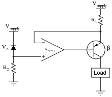
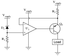
Explain how the operational amplifier maintains a constant current through the load:
|
|
Write an equation solving for the regulated load current, given any relevant variables shown in the schematic diagram (R1, VZ, Vsupply, AV(OL), etc.). Also, describe what would have to be changed in this circuit in order to set the regulated current at a different value.
|
Follow-up question: is the transistor sourcing current to the load, or sinking current from it?
Challenge question #1: modify the given equation to more precisely predict load current, taking the b of the transistor into account.
Challenge question #2: modify the location of the load in this circuit so that the given equation does precisely predict load current, rather than closely approximate load current.
Notes:
This is a good example of how operational amplifiers may greatly improve the functions of discrete-component circuits. In this case, the opamp performs the function of a current mirror circuit, and does so with greater precision and reliability than a simple current mirror ever could.
It should be noted that the equation provided in the answer does not directly predict the current through the load, rather it predicts current through resistor R2. This is equal to load current only if the transistor's base current is zero, which of course it cannot be. The real equation for predicting load current will be a bit more complex than what is given in the answer, and I leave it for your students to derive.
Question 5:
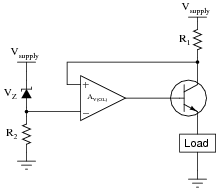
At first glance, the feedback appears to be wrong in this current-regulating circuit. Note how the feedback signal goes to the operational amplifier's noninverting (+) input, rather than the inverting input as one would normally expect for negative feedback:
|
|
Explain how this op-amp really does provide negative feedback, which of course is necessary for stable current regulation, as positive feedback would be completely unstable.
Notes:
The purpose of this question is to get students to realize negative feedback does not necessarily have to go into the inverting input. What makes the feedback "negative" is its self-correcting nature: the op-amp output drives in the direction opposite a perturbation in the measured signal in order to achieve stability at a control point.
Question 6:
Predict how the operation of this current regulator circuit will be affected as a result of the following faults. Consider each fault independently (i.e. one at a time, no multiple faults):
|
|
- �
- Resistor R1 fails open:
- �
- Zener diode D1 fails shorted:
- �
- Resistor R2 fails open:
- �
- Zener diode D1 fails open:
- �
- Load fails shorted:
- �
- Wire between opamp output and transistor base breaks open:
For each of these conditions, explain why the resulting effects will occur.
- �
- Resistor R1 fails open: Load current falls to zero.
- �
- Zener diode D1 fails shorted: Load current falls to zero.
- �
- Resistor R2 fails open: Load current falls to zero.
- �
- Zener diode D1 fails open: Load current increases.
- �
- Load fails shorted: Load current remains the same.
- �
- Wire between opamp output and transistor base breaks open: Load current falls to zero.
Follow-up question: which of the two opamp power terminals (Vsupply or Ground) carries more current during normal operation, and why?
Notes:
The purpose of this question is to approach the domain of circuit troubleshooting from a perspective of knowing what the fault is, rather than only knowing what the symptoms are. Although this is not necessarily a realistic perspective, it helps students build the foundational knowledge necessary to diagnose a faulted circuit from empirical data. Questions such as this should be followed (eventually) by other questions asking students to identify likely faults based on measurements.
Question 7:
Predict how the operation of this current regulator circuit will be affected as a result of the following faults. Consider each fault independently (i.e. one at a time, no multiple faults):
|
|
- �
- Resistor R1 fails open:
- �
- Resistor R2 fails open:
- �
- Solder bridge (short) across resistor R2:
- �
- Zener diode D1 fails shorted:
- �
- Zener diode D1 fails open:
- �
- Load fails shorted:
- �
- Wire between opamp output and transistor base breaks open:
For each of these conditions, explain why the resulting effects will occur.
- �
- Resistor R1 fails open: Load current falls to zero.
- �
- Resistor R2 fails open: Load current falls to zero.
- �
- Solder bridge (short) across resistor R2: Load current increases.
- �
- Zener diode D1 fails shorted: Load current falls to zero.
- �
- Zener diode D1 fails open: Load current increases.
- �
- Load fails shorted: Load current remains the same.
- �
- Wire between opamp output and transistor base breaks open: Load current falls to zero.
Follow-up question: which of the two opamp power terminals (Vsupply or Ground) carries more current during normal operation, and why?
Notes:
The purpose of this question is to approach the domain of circuit troubleshooting from a perspective of knowing what the fault is, rather than only knowing what the symptoms are. Although this is not necessarily a realistic perspective, it helps students build the foundational knowledge necessary to diagnose a faulted circuit from empirical data. Questions such as this should be followed (eventually) by other questions asking students to identify likely faults based on measurements.
Question 8:
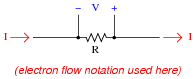
The simplest electronic device capable of converting a current signal into a voltage signal is a resistor:
|
|
Precision resistors typically work very well for this purpose, especially when the amount of voltage dropped across it is of little consequence. This is why shunt resistors are frequently used in power circuitry to measure current, a low-resistance ßhunt" resistance element dropping voltage in precise proportion to the current going through it.
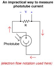
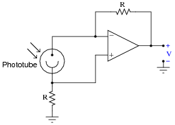
However, if we cannot afford to drop any voltage across a resistance in the circuit, this technique of current-to-voltage conversion will not be very practical. Consider the following scientific apparatus, used to measure the photoelectric effect (electrons emitted from a solid surface due to light striking it):
|
|
The current output by such a phototube is very small, and the voltage output by it is smaller yet. If we are to measure current through this device, we will have to find some way other than a shunt resistor to do it.
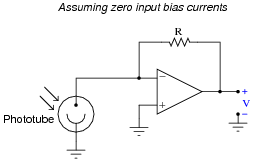
Enter the operational amplifier, to the rescue! Explain how the following opamp circuit is able to convert the phototube's weak current signal into a strong voltage signal, without imposing any significant resistance into the phototube circuit:
|
|
|
|
Notes:
Note to your students that this is one of those applications where even "tiny" input bias currents can affect the results. In this particular case, the phototube outputs miniscule current at best, and so we must compensate for the existence of opamp bias currents.
Question 9:
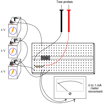
Shown here is a simple circuit for constructing an extremely high input impedance voltmeter on a wireless breadboard, using one half of a TL082 dual op-amp:
|
|
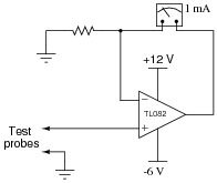
Draw a schematic diagram of this circuit, a calculate the resistor value necessary to give the meter a voltage measurement range of 0 to 5 volts.
|
|
R = 5 kW
Follow-up question: determine the approximate input impedance of this voltmeter, and also the maximum voltage it is able to measure with any size resistor in the circuit.
Notes:
This is a very practical circuit for your students to build, and they may find it outperforms their own (purchased) voltmeters in the parameter of input impedance! Be sure to ask them where they found the information on input impedance for the TL082 op-amp, and how they were able to determine the maximum input voltage for a circuit like this.