Precise diode circuits
Question 1:
| Don't just sit there! Build something!! |
Learning to mathematically analyze circuits requires much study and practice. Typically, students practice by working through lots of sample problems and checking their answers against those provided by the textbook or the instructor. While this is good, there is a much better way.
You will learn much more by actually building and analyzing real circuits, letting your test equipment provide the änswers" instead of a book or another person. For successful circuit-building exercises, follow these steps:
- 1.
- Carefully measure and record all component values prior to circuit construction.
- 2.
- Draw the schematic diagram for the circuit to be analyzed.
- 3.
- Carefully build this circuit on a breadboard or other convenient medium.
- 4.
- Check the accuracy of the circuit's construction, following each wire to each connection point, and verifying these elements one-by-one on the diagram.
- 5.
- Mathematically analyze the circuit, solving for all voltage and current values.
- 6.
- Carefully measure all voltages and currents, to verify the accuracy of your analysis.
- 7.
- If there are any substantial errors (greater than a few percent), carefully check your circuit's construction against the diagram, then carefully re-calculate the values and re-measure.
Avoid using the model 741 op-amp, unless you want to challenge your circuit design skills. There are more versatile op-amp models commonly available for the beginner. I recommend the LM324 for DC and low-frequency AC circuits, and the TL082 for AC projects involving audio or higher frequencies.
As usual, avoid very high and very low resistor values, to avoid measurement errors caused by meter "loading". I recommend resistor values between 1 kW and 100 kW.
One way you can save time and reduce the possibility of error is to begin with a very simple circuit and incrementally add components to increase its complexity after each analysis, rather than building a whole new circuit for each practice problem. Another time-saving technique is to re-use the same components in a variety of different circuit configurations. This way, you won't have to measure any component's value more than once.
Notes:
It has been my experience that students require much practice with circuit analysis to become proficient. To this end, instructors usually provide their students with lots of practice problems to work through, and provide answers for students to check their work against. While this approach makes students proficient in circuit theory, it fails to fully educate them.
Students don't just need mathematical practice. They also need real, hands-on practice building circuits and using test equipment. So, I suggest the following alternative approach: students should build their own "practice problems" with real components, and try to mathematically predict the various voltage and current values. This way, the mathematical theory "comes alive," and students gain practical proficiency they wouldn't gain merely by solving equations.
Another reason for following this method of practice is to teach students scientific method: the process of testing a hypothesis (in this case, mathematical predictions) by performing a real experiment. Students will also develop real troubleshooting skills as they occasionally make circuit construction errors.
Spend a few moments of time with your class to review some of the "rules" for building circuits before they begin. Discuss these issues with your students in the same Socratic manner you would normally discuss the worksheet questions, rather than simply telling them what they should and should not do. I never cease to be amazed at how poorly students grasp instructions when presented in a typical lecture (instructor monologue) format!
A note to those instructors who may complain about the "wasted" time required to have students build real circuits instead of just mathematically analyzing theoretical circuits:
What is the purpose of students taking your course?
If your students will be working with real circuits, then they should learn on real circuits whenever possible. If your goal is to educate theoretical physicists, then stick with abstract analysis, by all means! But most of us plan for our students to do something in the real world with the education we give them. The "wasted" time spent building real circuits will pay huge dividends when it comes time for them to apply their knowledge to practical problems.
Furthermore, having students build their own practice problems teaches them how to perform primary research, thus empowering them to continue their electrical/electronics education autonomously.
In most sciences, realistic experiments are much more difficult and expensive to set up than electrical circuits. Nuclear physics, biology, geology, and chemistry professors would just love to be able to have their students apply advanced mathematics to real experiments posing no safety hazard and costing less than a textbook. They can't, but you can. Exploit the convenience inherent to your science, and get those students of yours practicing their math on lots of real circuits!
Question 2:
A common type of graph used to describe the operation of an electronic component or subcircuit is the transfer characteristic, showing the relationship between input signal and output signal. For example, the transfer characteristic for a simple resistive voltage divider circuit is a straight line:
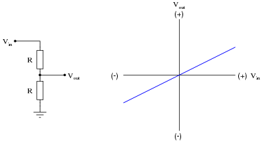
|
|
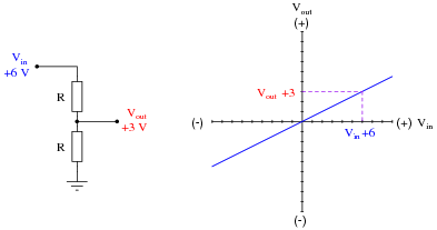
Once a transfer characteristic has been plotted, it may be used to predict the output signal of a circuit given any particular input signal. In this case, the transfer characteristic plot for the 2:1 voltage divider circuit tells us that the circuit will output +3 volts for an input of +6 volts:
|
|
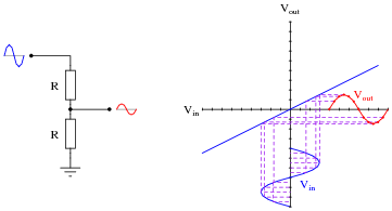
We may use the same transfer characteristic to plot the output of the voltage divider given an AC waveform input:
|
|
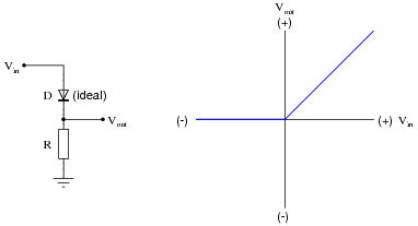
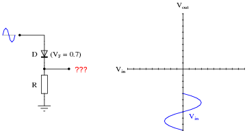
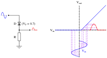
While this example (a voltage divider with a 2:1 ratio) is rather trivial, it shows how transfer characteristics may be used to predict the output signal of a network given a certain input signal condition. Where transfer characteristic graphs are more practical is in predicting the behavior of nonlinear circuits. For example, the transfer characteristic for an ideal half-wave rectifier circuit looks like this:
|
|
Sketch the transfer characteristic for a realistic diode (silicon, with 0.7 volts forward drop), and use this characteristic to plot the half-wave rectified output waveform given a sinusoidal input:
|
|
|
|
Notes:
Transfer characteristic graphs provide an elegant method to sketch the output waveshape for any electrical network, linear or nonlinear. The method in which points along an input waveform are reflected and transferred to equivalent points on the output waveform justifies the name of this analytical tool. Make sure your students get the opportunity to learn how to use this tool, as it can provide great insight into distortion in electronic and electromagnetic devices.
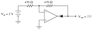
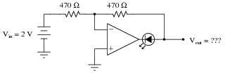
Question 3:
Determine the output voltage of this circuit, assuming a silicon diode (0.7 volts typical forward drop):
|
|
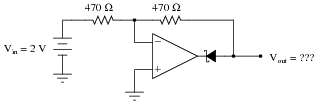
Now, determine the output voltage of the same circuit with a Schottky diode (0.4 volts typical forward drop) instead of a silicon PN junction diode:
|
|
Now, determine the output voltage of the same circuit with a light-emitting diode (1.7 volts typical forward drop):
|
|
Comment on these three circuits' output voltages: what does this indicate about the effect of the diode's voltage drop on the opamp output?
Follow-up question: what is different within these three circuits, if not the output voltage?
Notes:
By itself, these circuits are fairly useless. Their purpose is to prepare students to understand how precision rectifier circuits work, by showing how negative feedback makes the diode's forward voltage drop irrelevant. This is another example of the power of negative feedback, and an essential concept for understanding all precise (opamp-driven) diode circuits.
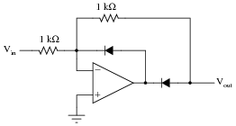
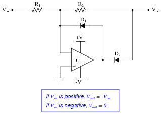
Question 4:
Determine the output voltage of this circuit for two different input voltage values: +5 volts, and -5 volts, assuming the use of ordinary silicon rectifying diodes:
|
|
Based on this data (and any other input conditions you wish to test this circuit under), describe what the function of this circuit is.
When Vin = -5 volts, Vout = 0 volts
This circuit is a precision rectifier.
Notes:
Work with your students to analyze the behavior of this circuit, using Ohm's Law and the basic principle of negative feedback (zero differential input voltage). Ask your students whether or not it matters what types of diodes are used (silicon versus germanium versus light-emitting).
Question 5:
This opamp circuit is called a precision rectifier. Analyze its output voltage as the input voltage smoothly increases from -5 volts to +5 volts, and explain why the circuit is worthy of its name:
|
|
Assume that both diodes in this circuit are silicon switching diodes, with a nominal forward voltage drop of 0.7 volts.
Follow-up question: would it affect the output voltage if the forward voltage drop of either diode increased? Explain why or why not.
Notes:
Precision rectifier circuits tend to be more difficult for students to comprehend than non-rectifying inverting or noninverting amplifier circuits. Spend time analyzing this circuit together in class with your students, asking them to determine the magnitudes of all voltages in the circuit (and directions of current) for given input voltage conditions.
Understanding whether or not changes in diode forward voltage drop affect a precision rectifier circuit's function is fundamental. If students comprehend nothing else about this circuit, it is the relationship between diode voltage drop and input/output transfer characteristics.
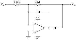
Question 6:
Explain why the following opamp circuit cannot be used as a rectifier in an AC-DC power supply circuit:
|
|
Notes:
Believe it or not, I actually sat in an electronics class one time and listened to an instructor present the precision rectifier opamp circuit as a "precision rectifier for a power supply". He was serious, too, claiming that this type of circuitry was used to provide split (+V/-V) voltage outputs for benchtop power supplies. The saddest part of this ordeal is that none of his students recognized anything wrong with his statement (or at least did not feel comfortable in raising a question about it).
Question 7:
Predict how the operation of this precision rectifier circuit will be affected as a result of the following faults. Consider each fault independently (i.e. one at a time, no multiple faults):
|
|
- �
- Resistor R1 fails open:
- �
- Resistor R2 fails open:
- �
- Diode D1 fails open:
- �
- Diode D2 fails open:
For each of these conditions, explain why the resulting effects will occur.
- �
- Resistor R1 fails open: Vout becomes equal to 0 volts all the time.
- �
- Resistor R2 fails open: Vout saturates negative when Vin is positive, and Vout floats up to +1.4 volts when Vin is negative (depending on how the output is loaded by another circuit).
- �
- Diode D1 fails open: Normal operation when Vin is positive (Vout = - Vin), Vout = Vin when Vin is negative (full-wave, inverted rectification!).
- �
- Diode D2 fails open: Normal operation when Vin is negative (Vout = 0 volts), Vout = Vin when Vin is positive (half-wave, non-inverted rectification!).
Notes:
The purpose of this question is to approach the domain of circuit troubleshooting from a perspective of knowing what the fault is, rather than only knowing what the symptoms are. Although this is not necessarily a realistic perspective, it helps students build the foundational knowledge necessary to diagnose a faulted circuit from empirical data. Questions such as this should be followed (eventually) by other questions asking students to identify likely faults based on measurements.
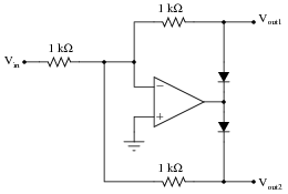
Question 8:
The following circuit is sometimes referred to as a polarity separator. Invent some test conditions you would use to "prove" the operation of the circuit, then analyze the circuit under those imagined conditions and see what the results are:
|
|
Explain what each output does in this "polarity separator" circuit for any given input voltage.
Notes:
This circuit is a good introduction to the full-wave precision rectifier circuit, although its operation there is a bit more difficult to understand than it is here.
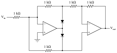
Question 9:
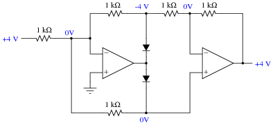
Determine the output voltage of this circuit for two different input voltage values: +4 volts, and -4 volts. Determine the voltage at each and every node with respect to ground as part of your analysis:
|
|
Based on this data (and any other input conditions you wish to test this circuit under), describe what the function of this circuit is.
|
|
|
|
This circuit is a precision full-wave rectifier.
Notes:
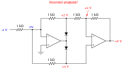
It is much easier to analyze the behavior of this circuit with a positive input voltage than it is to analyze it with a negative input voltage! There is a tendency for students to reach this conclusion when analyzing the circuit's behavior with a negative input voltage:
|
|
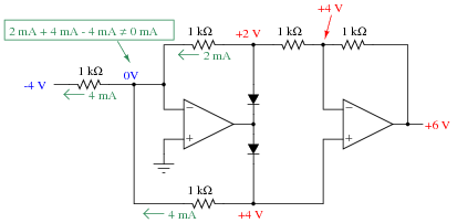
The error seems reasonable until an analysis of current is made. If these voltages were true, Kirchhoff's Current Law would be violated at the first opamp's virtual ground:
|
|
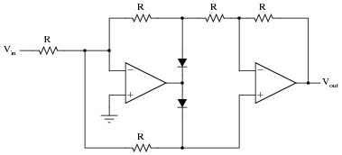
Question 10:
Explain how you could reverse the output polarity of this precision rectifier circuit:
|
|

|
|
Notes:
The answer to this question may seem too obvious to both asking. In reality, it's just another excuse to analyze the full-wave rectifier circuit, complete with all currents and voltage drops!
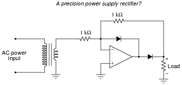
Question 11:
One problem with PMMC (permanent magnet moving coil) meter movements is trying to get them to register AC instead of DC. Since these meter movements are polarity-sensitive, their needles merely vibrate back and forth in a useless fashion when powered by alternating current:

|
|
The same problem haunts other measurement devices and circuits designed to work with DC, including most modern analog-to-digital conversion circuits used in digital meters. Somehow, we must be able to rectify the measured AC quantity into DC for these measurement circuits to properly function.
A seemingly obvious solution is to use a bridge rectifier made of four diodes to perform the rectification:
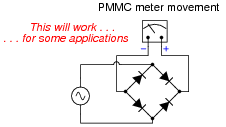
|
|
The problem here is the forward voltage drop of the rectifying diodes. If we are measuring large voltages, this voltage loss may be negligible. However, if we are measuring small AC voltages, the drop may be unacceptable.
Explain how a precision full-wave rectifier circuit built with an opamp may adequately address this situation.
Notes:
The purpose of this question is to provide a practical context for precision rectifier circuits, where students can envision a real application.
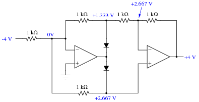
Question 12:
Suppose that diode D1 in this precision rectifier circuit fails open. What effect will this have on the output voltage?
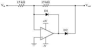
|
|
Hint: if it helps, draw a table of figures relating Vin with Vout, and base your answer on the tabulated results.
Challenge question: what mathematical function does this circuit perform, with diode D1 failed open?
Notes:
Note that the given failure does not render the circuit useless, but transforms its function into something different! This is an important lesson for students to understand: that component failures may not always results in complete circuit non-function. The circuit may continue to function, just differently. And, in some cases such as this, the new function may even appear to be intentional!
Question 13:
Determine the output voltage of this circuit for the following input voltage conditions:
- �
- V1 = +2 volts
- �
- V3 = -1.5 volts
- �
- V1 = +2.2 volts
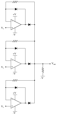
|
|
Hint: if you find this circuit too complex to analyze all at once, think of a way to simplify it so that you may analyze it one "piece" at a time.
Follow-up question: what function does this circuit perform? Can you think of any practical applications for it?
Notes:
Another facet of this question to ponder with your students is the simplification process, especially for those students who experience difficulty analyzing the whole circuit. What simplification methods did your students think of when they approached this problem? What conclusions may be drawn about the general concept of problem simplification (as a problem-solving technique)?
Question 14:
This circuit is referred to as a peak follower-and-hold, taking the last greatest positive input voltage and "holding" that value at the output until a greater positive input voltage comes along:
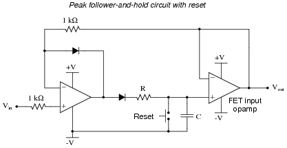
|
|
Give a brief explanation of how this circuit works, as well as the purpose and function of the "reset" switch. Also, explain why a FET input opamp is required for the last stage of amplification.
Follow-up question: how would you suggest choosing the values of resistor R and capacitor C?
Challenge question: redraw the circuit, replacing the mechanical reset switch with a JFET for electronic reset capability.
Notes:
Ask your students if they can think of any practical applications for this type of circuit. There are many!
I find it interesting that in two very respectable texts on opamp circuitry, I have found the following peak follower-and-hold circuit given as a practical example:
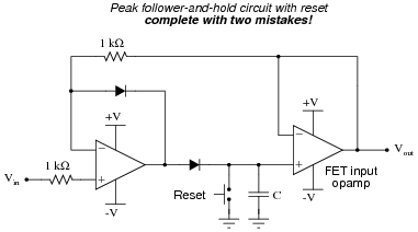
|
|
This circuit contains two mistakes: the first is by having the reset switch go to ground, rather than -V. This makes the reset function set the default output to 0 volts, which makes it impossible for the circuit to subsequently follow and hold any input signal below ground potential. The second mistake is not having a resistor before the reset switch. Without a resistor in place, closing the reset switch places a momentary short-circuit on the output of the first opamp. Granted, the presence of a resistor creates a passive integrator stage (RC time constant) which must be kept considerably fast in order that rapid changes in input will be followed and held, but this is not a difficult factor to engineer.