Oscillator circuits
Question 1:
| Don't just sit there! Build something!! |
Learning to mathematically analyze circuits requires much study and practice. Typically, students practice by working through lots of sample problems and checking their answers against those provided by the textbook or the instructor. While this is good, there is a much better way.
You will learn much more by actually building and analyzing real circuits, letting your test equipment provide the änswers" instead of a book or another person. For successful circuit-building exercises, follow these steps:
- 1.
- Carefully measure and record all component values prior to circuit construction, choosing resistor values high enough to make damage to any active components unlikely.
- 2.
- Draw the schematic diagram for the circuit to be analyzed.
- 3.
- Carefully build this circuit on a breadboard or other convenient medium.
- 4.
- Check the accuracy of the circuit's construction, following each wire to each connection point, and verifying these elements one-by-one on the diagram.
- 5.
- Mathematically analyze the circuit, solving for all voltage and current values.
- 6.
- Carefully measure all voltages and currents, to verify the accuracy of your analysis.
- 7.
- If there are any substantial errors (greater than a few percent), carefully check your circuit's construction against the diagram, then carefully re-calculate the values and re-measure.
When students are first learning about semiconductor devices, and are most likely to damage them by making improper connections in their circuits, I recommend they experiment with large, high-wattage components (1N4001 rectifying diodes, TO-220 or TO-3 case power transistors, etc.), and using dry-cell battery power sources rather than a benchtop power supply. This decreases the likelihood of component damage.
As usual, avoid very high and very low resistor values, to avoid measurement errors caused by meter "loading" (on the high end) and to avoid transistor burnout (on the low end). I recommend resistors between 1 kW and 100 kW.
One way you can save time and reduce the possibility of error is to begin with a very simple circuit and incrementally add components to increase its complexity after each analysis, rather than building a whole new circuit for each practice problem. Another time-saving technique is to re-use the same components in a variety of different circuit configurations. This way, you won't have to measure any component's value more than once.
Notes:
It has been my experience that students require much practice with circuit analysis to become proficient. To this end, instructors usually provide their students with lots of practice problems to work through, and provide answers for students to check their work against. While this approach makes students proficient in circuit theory, it fails to fully educate them.
Students don't just need mathematical practice. They also need real, hands-on practice building circuits and using test equipment. So, I suggest the following alternative approach: students should build their own "practice problems" with real components, and try to mathematically predict the various voltage and current values. This way, the mathematical theory "comes alive," and students gain practical proficiency they wouldn't gain merely by solving equations.
Another reason for following this method of practice is to teach students scientific method: the process of testing a hypothesis (in this case, mathematical predictions) by performing a real experiment. Students will also develop real troubleshooting skills as they occasionally make circuit construction errors.
Spend a few moments of time with your class to review some of the "rules" for building circuits before they begin. Discuss these issues with your students in the same Socratic manner you would normally discuss the worksheet questions, rather than simply telling them what they should and should not do. I never cease to be amazed at how poorly students grasp instructions when presented in a typical lecture (instructor monologue) format!
A note to those instructors who may complain about the "wasted" time required to have students build real circuits instead of just mathematically analyzing theoretical circuits:
What is the purpose of students taking your course?
If your students will be working with real circuits, then they should learn on real circuits whenever possible. If your goal is to educate theoretical physicists, then stick with abstract analysis, by all means! But most of us plan for our students to do something in the real world with the education we give them. The "wasted" time spent building real circuits will pay huge dividends when it comes time for them to apply their knowledge to practical problems.
Furthermore, having students build their own practice problems teaches them how to perform primary research, thus empowering them to continue their electrical/electronics education autonomously.
In most sciences, realistic experiments are much more difficult and expensive to set up than electrical circuits. Nuclear physics, biology, geology, and chemistry professors would just love to be able to have their students apply advanced mathematics to real experiments posing no safety hazard and costing less than a textbook. They can't, but you can. Exploit the convenience inherent to your science, and get those students of yours practicing their math on lots of real circuits!
Question 2:
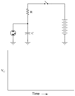
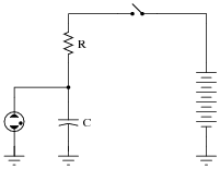
The circuit shown here is called a relaxation oscillator. It works on the principles of capacitor charging over time (an RC circuit), and of the hysteresis of a gas-discharge bulb: the fact that the voltage required to initiate conduction through the bulb is significantly greater than the voltage below which the bulb ceases to conduct current.
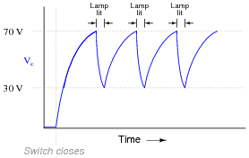
In this circuit, the neon bulb ionizes at a voltage of 70 volts, and stops conducting when the voltage falls below 30 volts:
|
|
Graph the capacitor's voltage over time as this circuit is energized by the DC source. Note on your graph at what times the neon bulb is lit:
|
|
Follow-up question: assuming a source voltage of 100 volts, a resistor value of 27 kW, and a capacitor value of 22 mF, calculate the amount of time it takes for the capacitor to charge from 30 volts to 70 volts (assuming the neon bulb draws negligible current during the charging phase).
Notes:
What we have here is a very simple strobe light circuit. This circuit may be constructed in the classroom with minimal safety hazard if the DC voltage source is a hand-crank generator instead of a battery bank or line-powered supply. I've demonstrated this in my own classroom before, using a hand-crank "Megger" (high-range, high-voltage ohmmeter) as the power source.
Question 3:
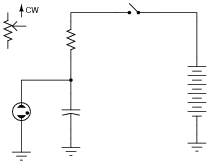
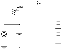
Replace the fixed-value resistor with a potentiometer to adjust the blinking rate of the neon lamp, in this relaxation oscillator circuit. Connect the potentiometer in such a way that clockwise rotation of the knob makes the lamp blink faster:
|
|
|
|
Notes:
Ask your students to explain why the potentiometer has the speed-changing effect it does on the circuit's flash rate. Would there be any other way to change this circuit's flash rate, without using a potentiometer?
Question 4:
Define what an oscillator circuit is, using your own words. Give a few examples of oscillators at work in common devices and systems.
- An öscillator" is a device that produces oscillations (back-and-forth) changes - usually an electronic circuit that produces AC - from a steady (DC) source of power.
Notes:
Oscillators are nearly ubiquitous in a modern society. If your students' only examples are electronic in nature, you may want to mention these mechanical devices:
- �
- Pendulum clock mechanism
- �
- Shaker (for sifting granular materials or mixing liquids such as paint)
- �
- Whistle
- �
- Violin string
Question 5:
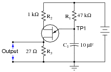
This relaxation oscillator circuit uses a resistor-capacitor combination (R1 - C1) to establish the time delay between output pulses:
|
|
The voltage measured between TP1 and ground looks like this on the oscilloscope display:
|
|
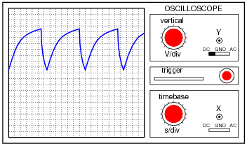
A slightly different version of this circuit adds a JFET to the capacitor's charge current path:
|
|
Now, the voltage at TP1 looks like this:
|
|
What function does the JFET perform in this circuit, based on your analysis of the new TP1 signal waveform? The straight-line charging voltage pattern shown on the second oscilloscope display indicates what the JFET is doing in this circuit.
Hint: you don't need to know anything about the function of the unijunction transistor (at the circuit's output) other than it acts as an on/off switch to periodically discharge the capacitor when the TP1 voltage reaches a certain threshold level.
Challenge question: write a formula predicting the slope of the ramping voltage waveform measured at TP1.
Answer to challenge question: Slope = [dv/dt] = [(ID)/C]
Notes:
Ask your students how they would know to relate "constant current" to the peculiar charging action of this capacitor. Ask them to explain this mathematically.
Then, ask them to explain exactly how the JFET works to regulate charging current.
Note: the schematic diagram for this circuit was derived from one found on page 958 of John Markus' Guidebook of Electronic Circuits, first edition. Apparently, the design originated from a Motorola publication on using unijunction transistors (Ünijunction Transistor Timers and Oscillators," AN-294, 1972).
Question 6:
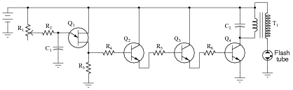
This circuit shown here is for a timing light: a device that uses a pulsed strobe lamp to "freeze" the motion of a rotating object.

|
|
Which component(s) in this circuit form the oscillator section? What type of oscillator is used in this circuit? Which component values have a direct influence on the frequency of the flash tube's output?
Challenge question: what purpose does resistor R2 serve? It would seem at first glance that it serves no useful purpose, as potentiometer R1 is capable of providing any desired amount of resistance for the RC time constant circuit on its own - R2's resistance is simply added to it. However, there is an important, practical reason for including R2 in the circuit. Explain what that reason is.
Notes:
Ask your students to explain what the other transistors do in this circuit. If time permits, explore the operation of the entire circuit with your students, asking them to explain the purpose and function of all components in it.
After they identify which components control the frequency of oscillation, ask them to specifically identify which direction each of those component values would need to be changed in order to increase (or decrease) the flash rate.
Question 7:
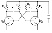
Explain the principle of operation in this astable multivibrator circuit:

|
|
Also, identify where you would connect to this circuit to obtain an output signal. What type of signal would it be (sine wave, square wave, ramp or triangle wave, etc.)?
Notes:
Ask your students to explain how the frequency of this circuit could be altered. After that, ask them what they would have to do to alter the duty cycle of this circuit's oscillation.
Question 8:
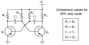
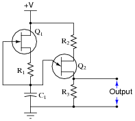
This astable multivibrator circuit will oscillate with a 50% duty cycle if the components are symmetrically sized:
|
|
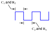
Determine which component(s) would have to be re-sized to produce a duty cycle other than 50%.
|
|
Challenge question: re-draw the schematic diagram to show how a potentiometer could be used to make the duty cycle adjustable over a wide range.
Notes:
Astable multivibrator circuits are simple and versatile, making them good subjects of study and discussion for your students.
Question 9:
If you have ever used a public address ("PA") amplifier, where sounds detected by a microphone are amplified and reproduced by speakers, you know how these systems can create ßcreeching" or "howling" sounds if the microphone is held too close to one of the speakers.
The noise created by a system like this is an example of oscillation: where the amplifier circuit spontaneously outputs an AC voltage, with no external source of AC signal to "drive" it. Explain what necessary condition(s) allow an amplifier to act as an oscillator, using a "howling" PA system as the example. In other words, what exactly is going on in this scenario, that makes an amplifier generate its own AC output signal?
Notes:
Ask your students to define what "positive feedback" is. In what way is the feedback in this system "positive," and how does this feedback differ from the "negative" variety commonly seen within amplifier circuitry?
Question 10:
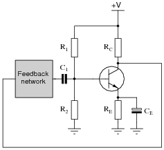
How many degrees of phase shift must the feedback circuit (the box in this schematic) introduce to the signal in order for this common-emitter amplifier circuit to oscillate?
|
|
We know that oscillator circuits require "regenerative" feedback in order to continuously sustain oscillation. Explain how the correct amount of phase shift is always provided in the feedback circuit to ensure that the nature of the feedback is always regenerative, not degenerative. In other words, explain why it is not possible to incorrectly choose feedback network component values and thus fail to achieve the proper amount of phase shift.
So long as the feedback network contains the correct types of components (resistors, capacitors, and/or inductors) in a working configuration, the components' values will not alter the amount of phase shift, only the frequency of the oscillation.
Notes:
Ask your students to explain why the feedback network must provide 180 degrees of phase shift to the signal. Ask them to explain how this requirement relates to the need for regenerative feedback in an oscillator circuit.
The question and answer concerning feedback component selection is a large conceptual leap for some students. It may baffle some that the phase shift of a reactive circuit will always be the proper amount to ensure regenerative feedback, for any arbitrary combination of component values, because they should know the phase shift of a reactive circuit depends on the values of its constituent components. However, once they realize that the phase shift of a reactive circuit is also dependent on the signal frequency, the resolution to this paradox is much easier to understand.
Question 11:
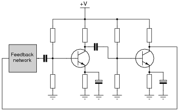
How many degrees of phase shift must the feedback circuit (the box in this schematic) introduce to the signal in order for this two-stage common-emitter amplifier circuit to oscillate?
|
|
Why is this amount of phase shift different from that of a single-transistor oscillator?
Notes:
Ask your students to explain why the feedback network must provide 180 degrees of phase shift to the signal. Ask them to explain how this requirement relates to the need for regenerative feedback in an oscillator circuit.
The question and answer concerning feedback component selection is a large conceptual leap for some students. It may baffle some that the phase shift of a reactive circuit will always be the proper amount to ensure regenerative feedback, for any arbitrary combination of component values, because they should know the phase shift of a reactive circuit depends on the values of its constituent components. However, once they realize that the phase shift of a reactive circuit is also dependent on the signal frequency, the resolution to this paradox is much easier to understand.
Question 12:
Explain what the Barkhausen criterion is for an oscillator circuit. How will the oscillator circuit's performance be affected if the Barkhausen criterion falls below 1, or goes much above 1?
Notes:
The question of "What is the Barkhausen criterion" could be answered with a short sentence, memorized verbatim from a textbook. But what I'm looking for here is real comprehension of the subject. Have your students explain to you the reason why oscillation amplitude depends on this factor.
Question 13:
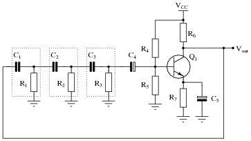
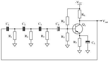
One way to achieve the phase shift necessary for regenerative feedback in an oscillator circuit is to use multiple RC phase-shifting networks:
|
|
What must the voltage gain be for the common-emitter amplifier if the total voltage attenuation for the three phase-shifting RC networks is -29.25 dB?
Notes:
This question probes students' comprehension of the Barkhausen criterion: that total loop gain must be equal or greater than unity in order for sustained oscillations to occur.
Question 14:
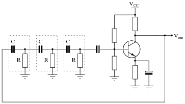
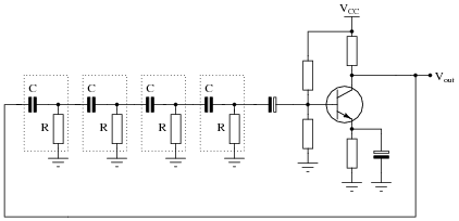
RC phase-shift oscillator circuits may be constructed with different numbers of RC sections. Shown here are schematic diagrams for three- and four-section RC oscillators:
|
|
|
|
What difference will the number of sections in the oscillator circuit make? Be as specific as you can in your answer.
Notes:
In either case, the point of the RC stages is to phase-shift the feedback signal by 180o. It is an over-simplification, though, to say that each stage in the three-section circuit shifts the signal by 60, and/or that each stage in the four-section circuit shifts the signal by 45o. The amount of phase-shift in each section will not be equal (with equal R and C values) due to the loading of each section by the previous section(s).
Question 15:
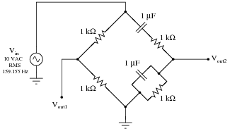
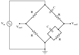
Calculate the output voltages of this Wien bridge circuit, if the input voltage is 10 volts RMS at a frequency of 159.155 Hz:
|
|
Vout2 = 3.33 VAC RMS � 0o
Notes:
This question provides an excellent opportunity for your students to review AC circuit analysis, as well as pave the way for questions regarding Wien bridge oscillator circuits!
Question 16:
In this Wien bridge circuit (with equal-value components all around), both output voltages will have the same phase angle only at one frequency:
|
|
At this same frequency, Vout2 will be exactly one-third the amplitude of Vin. Write an equation in terms of R and C to solve for this frequency.
|
|
|
|
|
|
|
|
|
|
|
|
Notes:
I chose to show the method of solution here because I find many of my students weak in manipulating imaginary algebraic terms (anything with a j in it). The answer is not exactly a give-away, as students still have to figure out how I arrived at the first equation. This involves both an understanding of the voltage divider formula as well as the algebraic expression of series impedances and parallel admittances.
It is also possible to solve for the frequency by only considering phase angles and not amplitudes. Since the only way Vout2 can have a phase angle of zero degrees in relation to the excitation voltage is for the upper and lower arms of that side of the bridge to have equal impedance phase angles, one might approach the problem in this fashion:
|
|
|
You might try presenting this solution to your students if imaginary algebra is too much for them at this point.
Question 17:
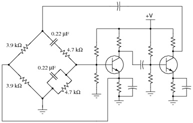
The circuit shown here is a Wien-bridge oscillator:
|
|
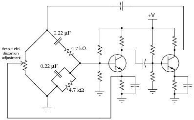
If one side of the Wien bridge is made from a potentiometer instead of two fixed-value resistors, this adjustment will affect both the amplitude and the distortion of the oscillator's output signal:
|
|
Explain why this adjustment has the effect that it does. What, exactly, does moving the potentiometer do to the circuit to alter the output signal? Also, calculate the operating frequency of this oscillator circuit, and explain how you would make that frequency adjustable as well.
f = 153.9 Hz
Follow-up question: identify the paths of positive and negative feedback from the Wien bridge to the first amplifier stage.
Notes:
One of the advantages of the Wien bridge circuit is its ease of adjustment in this manner. Using high-quality capacitors and resistors in the other side of the bridge, its output frequency will be very stable.
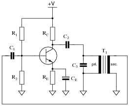
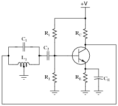
Question 18:
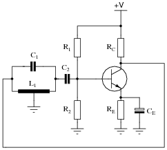
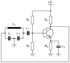
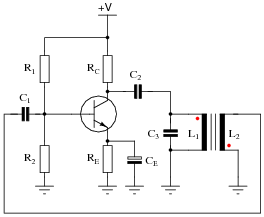
Identify the type of oscillator circuit shown in this schematic diagram, and explain the purpose of the tank circuit (L1 and C1):
|
|
Also, write the equation describing the operating frequency of this type of oscillator circuit.
|
Follow-up question: calculate the operating frequency of this oscillator circuit if L1 = 330 mH and C1 = 0.15 mF.
Notes:
Ask your students to describe the amount of phase shift the tank circuit provides to the feedback signal. Also, ask them to explain how the oscillator circuit's natural frequency may be altered.
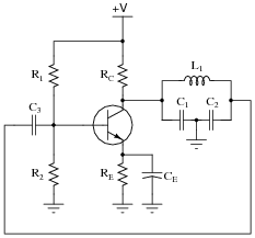
Question 19:
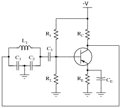
Identify the type of oscillator circuit shown in this schematic diagram, and explain the purpose of the tank circuit (L1, C1, and C2):
|
|
Also, write the equation describing the operating frequency of this type of oscillator circuit.
|
Follow-up question: calculate the operating frequency of this oscillator circuit if L1 = 270 mH, C1 = 0.047 mF, and C2 = 0.047 mF.
Notes:
Ask your students to describe the amount of phase shift the tank circuit provides to the feedback signal. Also, ask them to explain how the oscillator circuit's natural frequency may be altered.
Question 20:
Describe the purpose and operation of a crystal in an oscillator circuit. What physical principle does the crystal exploit, and what other components could be substituted in place of a crystal in an oscillator circuit?
Notes:
Ask your students to describe the phenomenon of piezoelectricity, and how this principle works inside an oscillator crystal. Also, ask them why crystals are used instead of tank circuits in so many precision oscillator circuits.
Question 21:
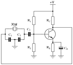
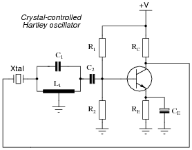
Identify the type of oscillator circuit shown in this schematic diagram, and explain the purpose of the crystal:
|
|
Challenge question: this type of oscillator circuit is usually limited to lower power outputs than either Hartley or Colpitts designs. Explain why.
Notes:
Ask your students to explain how the oscillator circuit's natural frequency may be altered. How does this differ from frequency control in either the Hartley or Colpitts designs?
Question 22:
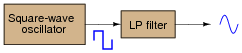
A clever way to produce sine waves is to pass the output of a square-wave oscillator through a low-pass filter circuit:
|
|
Explain how this principle works, based on your knowledge of Fourier's theorem.
Notes:
Ask your students what they think about the rolloff requirement for this LP filter. Will any LP filter work, or do we need something special?
Question 23:
Predict how the operation of this relaxation oscillator circuit will be affected as a result of the following faults. Consider each fault independently (i.e. one at a time, no multiple faults):
|
|
- �
- Capacitor C1 fails open:
- �
- Capacitor C1 fails shorted:
- �
- Resistor R1 fails open:
- �
- Solder bridge (short) past resistor R1:
For each of these conditions, explain why the resulting effects will occur.
- �
- Capacitor C1 fails open: Constant (unblinking) light from the neon bulb.
- �
- Capacitor C1 fails shorted: No light from the bulb at all.
- �
- Resistor R1 fails open: No light from the bulb at all.
- �
- Solder bridge (short) past resistor R1: Very bright, constant (unblinking) light from the bulb, possible bulb failure resulting from excessive current.
Notes:
The purpose of this question is to approach the domain of circuit troubleshooting from a perspective of knowing what the fault is, rather than only knowing what the symptoms are. Although this is not necessarily a realistic perspective, it helps students build the foundational knowledge necessary to diagnose a faulted circuit from empirical data. Questions such as this should be followed (eventually) by other questions asking students to identify likely faults based on measurements.
Question 24:
Predict how the operation of this strobe light circuit will be affected as a result of the following faults. Consider each fault independently (i.e. one at a time, no multiple faults):
|
|
- �
- Capacitor C1 fails open:
- �
- Capacitor C1 fails shorted:
- �
- Resistor R2 fails open:
- �
- Solder bridge (short) past resistor R2:
- �
- Resistor R4 fails open:
- �
- Transistor Q4 fails open (collector-to-emitter):
- �
- Capacitor C2 fails open:
- �
- Capacitor C2 fails shorted:
For each of these conditions, explain why the resulting effects will occur.
- �
- Capacitor C1 fails open: No light from flash tube, possible failure of transformer primary winding and/or transistor Q4 due to overheating.
- �
- Capacitor C1 fails shorted: No light from flash tube.
- �
- Resistor R2 fails open: No light from flash tube.
- �
- Solder bridge (short) past resistor R2: Faster strobe rate for any given position of potentiometer R1, possibility of adjusting the strobe rate too high where the flash tube just refuses to flash.
- �
- Resistor R4 fails open: No light from flash tube.
- �
- Transistor Q4 fails open (collector-to-emitter): No light from flash tube.
- �
- Capacitor C2 fails open: Possible damage to transistor Q4 from excessive transient voltages.
- �
- Capacitor C2 fails shorted: No light from flash tube, Q4 will almost certainly fail due to overheating.
Notes:
The purpose of this question is to approach the domain of circuit troubleshooting from a perspective of knowing what the fault is, rather than only knowing what the symptoms are. Although this is not necessarily a realistic perspective, it helps students build the foundational knowledge necessary to diagnose a faulted circuit from empirical data. Questions such as this should be followed (eventually) by other questions asking students to identify likely faults based on measurements.
Question 25:
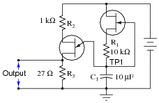
Predict how the operation of this sawtooth-wave oscillator circuit will be affected as a result of the following faults. Consider each fault independently (i.e. one at a time, no multiple faults):
|
|
- �
- Capacitor C1 fails shorted:
- �
- Resistor R1 fails open:
- �
- JFET fails shorted (drain-to-source):
- �
- Resistor R3 fails open:
For each of these conditions, explain why the resulting effects will occur.
- �
- Capacitor C1 fails shorted: No oscillation, low DC voltage output.
- �
- Resistor R1 fails open: No oscillation, low DC voltage output.
- �
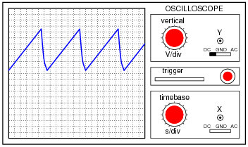
- JFET fails shorted (drain-to-source): Oscillation waveform looks "rounded" instead of having a straight leading edge, frequency is higher than normal.
- �
- Resistor R3 fails open: No oscillation, high DC voltage output.
Notes:
The purpose of this question is to approach the domain of circuit troubleshooting from a perspective of knowing what the fault is, rather than only knowing what the symptoms are. Although this is not necessarily a realistic perspective, it helps students build the foundational knowledge necessary to diagnose a faulted circuit from empirical data. Questions such as this should be followed (eventually) by other questions asking students to identify likely faults based on measurements.
Question 26:
Predict how the operation of this astable multivibrator circuit will be affected as a result of the following faults. Specifically, identify the final states of the transistors (on or off) resulting from each fault. Consider each fault independently (i.e. one at a time, no multiple faults):
|
|
- �
- Capacitor C1 fails open:
- �
- Capacitor C2 fails open:
- �
- Resistor R1 fails open:
- �
- Resistor R2 fails open:
- �
- Resistor R3 fails open:
- �
- Resistor R4 fails open:
For each of these conditions, explain why the resulting effects will occur.
- �
- Capacitor C1 fails open: Q2 immediately on, Q1 on after short time delay.
- �
- Capacitor C2 fails open: Q1 immediately on, Q2 on after short time delay.
- �
- Resistor R1 fails open: Q2 on, Q1 will have base current but no collector current.
- �
- Resistor R2 fails open: Q1 on, Q2 off.
- �
- Resistor R3 fails open: Q2 on, Q1 off.
- �
- Resistor R4 fails open: Q1 on, Q2 will have base current but no collector current.
Notes:
The purpose of this question is to approach the domain of circuit troubleshooting from a perspective of knowing what the fault is, rather than only knowing what the symptoms are. Although this is not necessarily a realistic perspective, it helps students build the foundational knowledge necessary to diagnose a faulted circuit from empirical data. Questions such as this should be followed (eventually) by other questions asking students to identify likely faults based on measurements.
Question 27:
Predict how the operation of this astable multivibrator circuit will be affected as a result of the following faults. Specifically, identify the signals found at test points TP1, TP2, TP3, and Vout resulting from each fault. Consider each fault independently (i.e. one at a time, no multiple faults):
|
|
- �
- Resistor R4 fails open:
- �
- Resistor R5 fails open:
- �
- Resistor R7 fails open:
- �
- Resistor R9 fails open:
- �
- Capacitor C7 fails shorted:
- �
- Capacitor C4 fails shorted:
- �
- Capacitor C5 fails open:
- �
- Transistor Q3 fails open (collector-to-emitter):
For each of these conditions, explain why the resulting effects will occur.
- �
- Resistor R4 fails open: Zero volts DC and AC at all four test points except for TP3 where there will be normal DC bias voltage.
- �
- Resistor R5 fails open: Normal signal at TP1, zero volts AC and DC at all other test points except for TP3 where there will be normal DC bias voltage.
- �
- Resistor R7 fails open: Normal signals at TP1 and at TP2, zero volts AC and DC at all other test points except for TP3 where there will be normal DC bias voltage.
- �
- Resistor R9 fails open: Normal signals at TP1, at TP2, and at TP3, but zero volts AC and DC at Vout.
- �
- Capacitor C7 fails shorted: Normal AC signals at TP1, at TP2, and at TP3, badly distorted waveform at Vout, only about 0.7 volts DC bias at TP3.
- �
- Capacitor C4 fails shorted: Normal signal at TP1, zero volts AC and DC at all other test points except for TP3 where there will be normal DC bias voltage.
- �
- Capacitor C5 fails open: Normal signals at TP1 and at TP2, zero volts AC and DC at all other test points except for TP3 where there will be normal DC bias voltage.
- �
- Transistor Q3 fails open (collector-to-emitter): Normal signals at TP1 and at TP2, zero volts AC and DC at all other test points except for TP3 where there will be normal DC bias voltage.
Notes:
The purpose of this question is to approach the domain of circuit troubleshooting from a perspective of knowing what the fault is, rather than only knowing what the symptoms are. Although this is not necessarily a realistic perspective, it helps students build the foundational knowledge necessary to diagnose a faulted circuit from empirical data. Questions such as this should be followed (eventually) by other questions asking students to identify likely faults based on measurements.
Question 28:
Identify some realistic component failures that would definitely prevent this oscillator circuit from oscillating:
|
|
For each of the faults you propose, explain why the oscillations will cease.
- �
- Solder bridge shorting across any of the phase-shift resistors (R1 through R3).
- �
- Resistor R4 failing open.
- �
- Transistor Q1 failing in any mode.
Follow-up question: how would you rank the listed faults in order of probability? In other words, which of these faults do you suppose would be more likely than the others, least likely than the others, etc.?
Notes:
The purpose of this question is to approach the domain of circuit troubleshooting from a perspective of assessing probable faults given very limited information about the circuit's behavior. An important part of troubleshooting is being able to decide what faults are more likely than others, and questions such as this help develop that skill.
Question 29:
Suppose some of the turns of wire (but not all) in the primary winding of the transformer were to fail shorted in this Armstrong oscillator circuit:
|
|
How would this effective decreasing of the primary winding turns affect the operation of this circuit? What if it were the secondary winding of the transformer to suffer this fault instead of the primary?
Notes:
The purpose of this question is to approach the domain of circuit troubleshooting from a perspective of knowing what the fault is, rather than only knowing what the symptoms are. Although this is not necessarily a realistic perspective, it helps students build the foundational knowledge necessary to diagnose a faulted circuit from empirical data. Questions such as this should be followed (eventually) by other questions asking students to identify likely faults based on measurements.
Question 30:
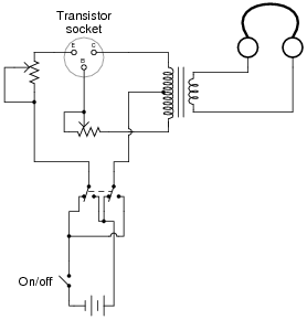
A technician is given a transistor testing circuit to repair. This simple circuit is an audio-frequency oscillator, and has the following schematic diagram:
|
|
After repairing a broken solder joint, the technician notices that the DPDT switch has lost its label. The purpose of this switch is to allow polarity to be reversed so as to test both PNP and NPN transistor types. However, the label showing which direction is for NPN and which direction is for PNP has fallen off. And, to make matters worse, the schematic diagram does not indicate which position is which.
Determine what the proper DPDT switch label should be for this transistor tester, and explain how you know it is correct. Note: you do not even have to understand how the oscillator circuit works to be able to determine the proper switch label. All you need to know is the proper voltage polarities for NPN and PNP transistor types.
Notes:
This is a very realistic problem for a technician to solve. Of course, one could determine the proper switch labeling experimentally (by trying a known NPN or PNP transistor and seeing which position makes the oscillator work), but students need to figure this problem out without resorting to trial and error. It is very important that they learn how to properly bias transistors!
Be sure to ask your students to explain how they arrived at their conclusion. It is not good enough for them to simply repeat the given answer!
Question 31:
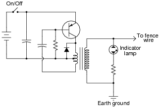
This electric fence-charging circuit, which is designed to produce short, high-voltage pulses on its output, has failed. Now, it produces no output voltage at all:
|
|
A technician does some troubleshooting and determines that the transistor is defective. She replaces the transistor, and the circuit begins to work again, its rhythmic output pulses indicated by the neon lamp.
But after producing only a few pulses, the circuit stops working. Puzzled, the technician troubleshoots it again and finds that the transistor has failed (again). Both the original and the replacement transistor were of the correct part number for this circuit, so the failure is not due to an incorrect component being used. Something is causing the transistor to fail prematurely. What do you suppose it is?
Notes:
There are many things in this circuit that could prevent it from generating output voltage pulses, but a failed diode (subsequently causing the transistor to fail) is the only problem I can think of which would allow the circuit to briefly function properly after replacing the transistor, and yet fail once more after only a few pulses. Students will likely suggest other possibilities, so be prepared to explore the consequences of each, determining whether or not the suggested failure(s) would account for all observed effects.
While your students are giving their reasoning for the diode as a cause of the problem, take some time and analyze the operation of the circuit with them. How does this circuit use positive feedback to support oscillations? How could the output pulse rate be altered? What is the function of each and every component in the circuit?
This circuit provides not only an opportunity to analyze a particular type of amplifier, but it also provides a good review of capacitor, transformer, diode, and transistor theory.
Question 32:
Spring- and weight-driven clock mechanisms always use a pendulum as an integral part of their workings. What function does a pendulum serve in a clock? What would a mechanical clock mechanism do if the pendulum were removed?
Describe what the electrical equivalent of a mechanical pendulum is, and what purpose it might serve in an oscillator circuit.
Notes:
Ask your students to brainstorm possible applications for electrical oscillator circuits, and why frequency regulation might be an important feature.
Question 33:
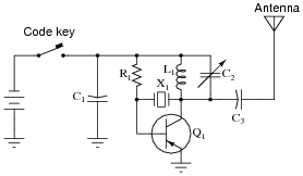
Two technicians are arguing over the function of a component in this oscillator circuit. Capacitor C1 has failed, and they are debating over the proper value of its replacement.
|
|
One technician argues that the value of capacitor C1 helps set the oscillation frequency of the circuit, and that the value of the replacement capacitor therefore must be precisely matched to the value of the original. The other technician thinks its value is not critical at all, arguing that all it does is help to provide a stable DC power supply voltage. What do you think?
Also, describe the purpose of this circuit: what is it?
The second technician is closer to the truth than the first, with regard to the capacitor. C1 is not part of the oscillator's resonant network, and so does not set the oscillation frequency. However, if the replacement capacitor's value is too far from the original's value, this circuit will not start and stop oscillating as "crisply" as it did before, when the code key switch is repeatedly actuated.
Notes:
Ask your students how they can tell that C1 is not part of the oscillator's resonant network.
Question 34:
How many degrees of phase shift must the feedback circuit (the square box in this schematic) introduce to the signal in order for this inverting amplifier circuit to oscillate?

|
|
Notes:
Ask your students to explain why the feedback network must provide 180 degrees of phase shift to the signal. Ask them to explain how this requirement relates to the need for regenerative feedback in an oscillator circuit.
Question 35:
How many degrees of phase shift must the feedback circuit (the square box in this schematic) introduce to the signal in order for this noninverting amplifier circuit to oscillate?
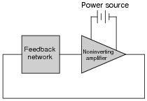
|
|
Notes:
Ask your students to explain why the feedback network must provide 180 degrees of phase shift to the signal. Ask them to explain how this requirement relates to the need for regenerative feedback in an oscillator circuit.
Question 36:
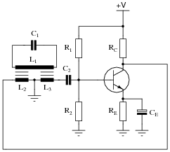
Identify the type of oscillator circuit shown in this schematic diagram, and explain the purpose of the tank circuit (L1 and C1):
|
|
Also, write the equation describing the operating frequency of this type of oscillator circuit.
|
Notes:
Ask your students to describe the amount of phase shift the tank circuit provides to the feedback signal. Also, ask them to explain how the oscillator circuit's natural frequency may be altered.
This circuit is unusual, as inductors L2 and L3 are not coupled to each other, but each is coupled to tank circuit inductor L1.
Question 37:
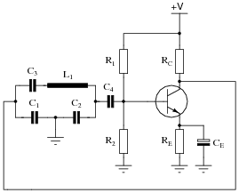
Identify the type of oscillator circuit shown in this schematic diagram:
|
|
Also, write the equation describing the operating frequency of this type of oscillator circuit.
|
Follow-up question: you may notice that the Clapp oscillator is just a variation of the Colpitts oscillator design. If C3 is much smaller than either C1 or C2, the frequency stability of the oscillator circuit will be relatively unchanged by variations in parasitic capacitance throughout the circuit (especially transistor junction "Miller effect" capacitances). Explain why, and how the following equation provides an approximation of operating frequency under these conditions:
|
Notes:
Ask your students to describe the amount of phase shift the tank circuit provides to the feedback signal. Also, ask them to explain how the oscillator circuit's natural frequency may be altered.
The only "trick" to figuring out the answer here is successfully identifying which capacitors are part of the tank circuit and which are not. Remind your students if necessary that tank circuits require direct (galvanic) connections between inductance and capacitance to oscillate - components isolated by an amplifier stage or a significant resistance cannot be part of a proper tank circuit. The identity of the constituent components may be determined by tracing the path of oscillating current between inductance(s) and capacitance(s).
Question 38:
Identify the type of oscillator circuit shown in this schematic diagram, and draw the transformer phasing dots in the right places to ensure regenerative feedback:

|
|
Also, write the equation describing the operating frequency of this type of oscillator circuit.
|
|
|
Notes:
Ask your students to describe the amount of phase shift the transformer-based tank circuit provides to the feedback signal. Having them place phasing dots near the transformer windings is a great review of this topic, and a practical context for winding "polarity". Also, ask them to explain how the oscillator circuit's natural frequency may be altered.
Question 39:
Modify the schematic diagram for a Hartley oscillator to include a crystal. What advantage(s) does a crystal-controlled Hartley oscillator exhibit over a regular Hartley oscillator?
|
|
Follow-up question: does the resonant frequency of the tank circuit have to match the crystal's resonant frequency? Why or why not?
Notes:
Ask your students to explain what purpose a crystal serves in an oscillator circuit that already contains a tank circuit for tuning.
Question 40:
How does the quality factor (Q) of a typical quartz crystal compare to that of a regular LC tank circuit, and what does this indicate about the frequency stability of crystal-controlled oscillators?
Notes:
Note that I did not answer the frequency stability question, but left that for the students to figure out.
Question 41:
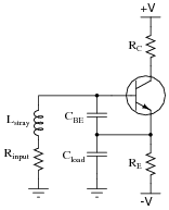
Under certain conditions (especially with certain types of loads) it is possible for a simple one-transistor voltage amplifier circuit to oscillate:
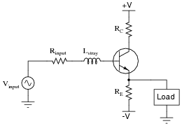
|
|
Explain how this is possible. What parasitic effects could possibly turn an amplifier into an oscillator?
|
|
Follow-up question: what type of oscillator circuit does this resemble?
Challenge question: what type(s) of load would tend to make this circuit oscillate more readily than others?
Notes:
This question reinforces a very important lesson in electronic circuit design: parasitic effects may produce some very unexpected consequences! Just because you didn't intend for your amplifier circuit to oscillate does not mean than it won't.
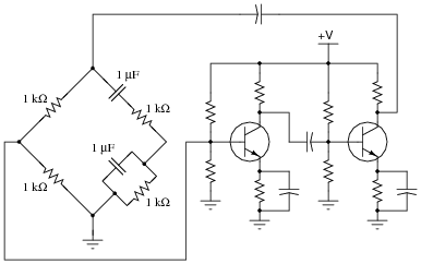
Question 42:
Calculate the operating frequency of this oscillator circuit:

|
|
Explain why the operating frequency will not be the same if the transistor receives its feedback signal from the other side of the bridge, like this:
|
|
If the feedback signal comes from the other side of the bridge, the feedback signal's phase shift will be determined by a different set of components (primarily, the coupling capacitors and bias network resistances) rather than the reactive arms of the bridge.
Notes:
Given the phase shift requirements of a two-stage oscillator circuit such as this, some students may wonder why the circuit won't act the same in the second configuration. If such confusion exists, clarify the concept with a question: "What is the phase relationship between input and output voltages for the bridge in these two configurations, over a wide range of frequencies?" From this observation, your students should be able to tell that only one of these configurations will be stable at 159.155 Hz.
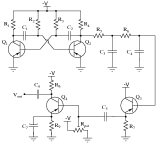
Question 43:
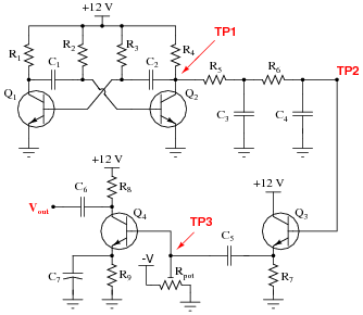
This circuit generates quasi-sine waves at its output. It does so by first generating square waves, integrating those square waves (twice) with respect to time, then amplifying the double-integrated signal:
|
|
Identify the sections of this circuit performing the following functions:
- �
- Square wave oscillator:
- �
- First integrator stage:
- �
- Second integrator stage:
- �
- Buffer stage (current amplification):
- �
- Final gain stage (voltage amplification):
- �
- Square wave oscillator: R1 through R4, C1 and C2, Q1 and Q2
- �
- First integrator stage: R5 and C3
- �
- Second integrator stage: R6 and C4
- �
- Buffer stage (current amplification): Q3 and R7
- �
- Final gain stage (voltage amplification): R8 and R9, Rpot, Q4, and C7
Notes:
The purpose of this question is to have students identify familiar sub-circuits within a larger, practical circuit. This is a very important skill for troubleshooting, as it allows technicians to divide a malfunctioning system into easier-to-understand sections.
Question 44:
Calculate the operating frequency of the following oscillator circuit, if C1 = 0.033 mF and L1 = 175 mH:

|
|
Notes:
Note to your students that the following formula (used to obtain the answer shown) is valid only if the tank circuit's Q factor is high (at least 10 is the rule-of-thumb):
|
Question 45:
Calculate the operating frequency of the following oscillator circuit, if C1 = 0.047 mF and L1 = 150 mH:
|
|
Notes:
Note to your students that the following formula (used to obtain the answer shown) is valid only if the tank circuit's Q factor is high (at least 10 is the rule-of-thumb):
|
Question 46:
Calculate the operating frequency of the following oscillator circuit, if C1 = 0.027 mF and L1 = 105 mH:

|
|
Notes:
Note to your students that the following formula (used to obtain the answer shown) is valid only if the tank circuit's Q factor is high (at least 10 is the rule-of-thumb):
|
Question 47:
Calculate the operating frequency of the following oscillator circuit, if C1 = 0.003 mF, C2 = 0.003 mF, and L1 = 50 mH:

|
|
Notes:
Note to your students that the following formula (used to obtain the answer shown) is valid only if the tank circuit's Q factor is high (at least 10 is the rule-of-thumb):
|
Question 48:
Calculate the operating frequency of the following oscillator circuit, if C1 = 0.005 mF, C2 = 0.005 mF, and L1 = 80 mH:
|
|
Notes:
Note to your students that the following formula (used to obtain the answer shown) is valid only if the tank circuit's Q factor is high (at least 10 is the rule-of-thumb):
|
Question 49:
Calculate the operating frequency of the following oscillator circuit, if C1 = 0.027 mF, C2 = 0.027 mF, and L1 = 220 mH:
|
|
Notes:
Note to your students that the following formula (used to obtain the answer shown) is valid only if the tank circuit's Q factor is high (at least 10 is the rule-of-thumb):
|