Overcurrent protection
Question 1:
What hazards might be posed by a circuit with excessive current going through its conductors (excessive as defined by the conductors' ampacity)? In other words, what would be bad about a wire carrying too much current?
Also determine which type of component fault, an open or a short, would most likely be the cause of excessive current in a circuit.
A shorted component could cause excessive current in a circuit, but an open fault will result in less (or no) current.
Notes:
Even if an overloaded wire does not get hot enough to ignite nearby combustible material, there are other ill effects of conductor overloading. Challenge your students to think of some other, negative consequences which may result from conductor overloading.
One of the goals of this question is for students to be able to distinguish between open and short component faults.
Question 2:
Explain the construction and purpose of an electrical fuse.
Notes:
Fuses come in many different styles and sizes. It would be good to have an array of fuses available for your students to see and hold during discussion time.
Question 3:
What is the difference between a fuse and a circuit breaker?
Notes:
There used to be a time when overcurrent protection for household circuits was primarily provided by fuses. In modern times, however, fuses are obsolete for household wiring - circuit breakers have completely taken their place. Discuss the relative advantages and disadvantages of these two overcurrent protection technologies.
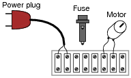
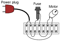
Question 4:
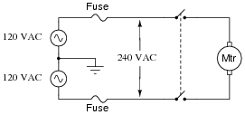
Show the proper placement of the fuse in this circuit, where an electric motor will be powered by utility (120 volt AC) power:
|
|
|
|
Notes:
You can redirect this question into one more general: should fuses be connected in series with the load, or in parallel with the load? Have your students explain their choices, based on their knowledge of series and parallel circuits.
Question 5:
Are fuses and circuit breakers located at a power distribution panel rated to protect the wiring from overcurrent, or to protect the load devices from overcurrent? Explain your answer.
Follow-up question: suppose a computer with a 300 watt power supply is plugged into a receptacle, which is serviced by a circuit breaker rated at 15 amps. Where in the circuit would it be best to install an overcurrent protection device for protecting the computer from burning itself up in the event of an internal failure?
Notes:
This lesson is very important for students to learn: that panel-mounted overcurrent protection devices are rated to protect the wiring they supply power to, and nothing else. Of course, there are exceptions to this rule in large industrial power systems.
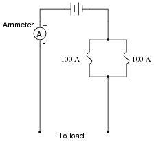
Question 6:
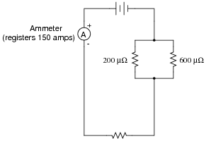
In an effort to obtain greater overcurrent ratings than a single fuse can provide, an engineer decides to wire two 100 amp fuses in parallel, for a combined rating of 200 amps:
|
|
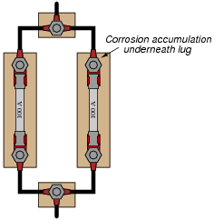
However, after a few years of operation, the system begins blowing fuses even when the ammeter registers less than 200 amps of load current. Upon investigation, it is found that one of the fuse holders had developed corrosion on a terminal lug where one of the wire connects:
|
|
Explain how a small accumulation of corrosion led to this condition of fuses blowing when there was no overcurrent condition (load current less than 200 amps), and also why connecting fuses in parallel like this is generally not a good idea.
|
|
Notes:
Ask your students to explain what happens to current in a circuit when it branches from one path into two or more parallel paths. Discuss how the proportionality of the current ßplit" between those paths depends on the relative resistances of those two paths.
Even if your students have not yet studied current divider circuits, this question provides an excellent opportunity to explore the concept.
Incidentally, it is now common for some manufacturers of residential power distribution equipment to "gang" circuit breakers together in parallel for added overcurrent capacity. This engineering practice is questionable for the exact same reason it is questionable with the fuses in this scenario: any amount of corrosion or other infiltration of electrical resistance into one of the parallel "legs" offsets the split of current between the paralleled overcurrent protection devices, forcing one of them to handle a disproportionately large share of the total current (and therefore trip sooner).
Question 7:
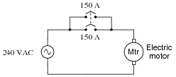
Two 150-amp circuit breakers are connected in parallel to obtain a total ampacity of 300 amperes for an electric motor service. The system works just fine for several years, but then both breakers begin to spuriously trip:
|
|
An electrician measures motor current using a clamp-on ammeter, and discovers the motor's current is no more than 228 amperes at full mechanical load. Describe what might possibly be wrong that is causing both circuit breakers to trip.
Notes:
This is a very practical problem, directly dealing with parallel resistances. Unfortunately, I have seen residential circuit breaker panels new from the manufacturer, equipped with paralleled breakers! Bad idea . . . baaaaaad idea.
Something worthwhile to note as a possible cause of the tripping is a spurious motor problem. Perhaps the circuit breakers are sharing current equally after all, but the motor is occasionally drawing more than 300 amps of current! Just because an electrician measured less than 300 amps at full load does not mean the motor never draws more than 300 amps. There may be another problem after all. Discuss this with your students, asking them how they would identify such a problem after having determined the two circuit breakers were doing their job correctly.
Question 8:
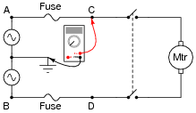
A large industrial electric motor is supplied power through a pair of fuses:
|
|
One day the motor suddenly stops running, even though the switch is still in the ön" position. An electrician is summoned to troubleshoot the failed motor, and this person decides to perform some voltage measurements to determine whether or not one of the fuses has "blown" open before doing anything else. The measurements taken by the electrician are as such (with the switch in the ön" position):
|
|
- �
- Between A and ground = 120 volts AC
- �
- Between B and ground = 120 volts AC
- �
- Between C and ground = 120 volts AC
- �
- Between D and ground = 120 volts AC
Based on these measurements, the electrician decides that both fuses are still in good condition, and that the problem lies elsewhere in the circuit. Do you agree with this assessment? Why or why not?
Follow-up question: what voltage measurement(s) would conclusively test the condition of both fuses?
Notes:
I have actually seen an experienced electrician make this mistake on the job! Ask your students to explain how full voltage could be measured at points C and D, with respect to ground, even with one of the fuses blown.
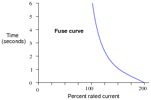
Question 9:
Explain the meaning of this fuse curve:
|
|
Notes:
There is far more to the behavior of a fuse than a single current rating, as this "fuse curve" graph illustrates. Discuss with your students the significance of such a curve, and under what conditions a fuse can sustain a current greater than its rating.
Question 10:
Magnetic circuit breakers trip by the action of an electromagnet coil, through which all the load current passes. When the attractive force of the magnetic field is strong enough, a mechanism triggers to snap the breaker contacts open, thus interrupting the circuit current.
What would the time-current curve for such a circuit breaker look like?

|
|

|
|
Notes:
Magnetic-trip circuit breakers are very common in industry, but they are not appropriate for all applications. Discuss this with your students, and try to think of applications where such an overcurrent protection device would not be appropriate.
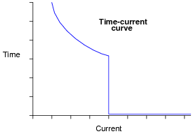
Question 11:
Shown here is the time-current curve for a dual-element fuse. Thermal-magnetic circuit breakers exhibit similar time-current curves:
|
|
Based on this curve, what do you think the purpose of a "dual-element" fuse or "thermal-magnetic" circuit breaker is? Why would this style of overcurrent protection device be chosen over a "normal" fuse or circuit breaker?
Notes:
Obviously, not all overcurrent conditions are the same. Ask your students to describe circuit faults that would cause slight overcurrent, versus faults that would cause extreme overcurrent in a circuit, and discuss the destructive consequences of each type of condition.
Question 12:
In addition to possessing a primary current rating, fuses and circuit breakers also possess an interruption current rating, usually far in excess of their primary ratings. For example, a typical 15 amp circuit breaker for 120 volt residential use may have an interruption rating of 10,000 amps (10 kA)! Under what conditions could such a circuit ever bear so much current, and why is this rating different than the breaker's primary current rating of 15 amps?
Notes:
Students will naturally wonder how a blown fuse or a tripped circuit breaker could not stop a fault current, since there is no longer a condition of electrical continuity between its terminals once it has opened. Or is there? Discuss with your students how an electric current of enormous magnitude could possibly continue to conduct through a blown fuse or tripped circuit breaker.
Question 13:
Find one or two real fuses and bring them with you to class for discussion. Identify as much information as you can about your fuses prior to discussion:
- �
- Current rating
- �
- Voltage rating
- �
- Interruption rating
- �
- Fuse curve (opening characteristics: fast-acting, slow-blow, etc.)
- �
- Status of fuse (blown or not)
Be prepared to prove the status of your fuse in class, using your multimeter!
Notes:
The purpose of this question is to get students to kinesthetically interact with the subject matter. It may seem silly to have students engage in a ßhow and tell" exercise, but I have found that activities such as this greatly help some students. For those learners who are kinesthetic in nature, it is a great help to actually touch real components while they're learning about their function. Of course, this question also provides an excellent opportunity for them to practice interpreting component markings, use a multimeter, access datasheets, etc.