Polyphase power systems
Question 1:
Explain the difference between a balanced polyphase system and an unbalanced polyphase system. What conditions typically cause a polyphase system to become unbalanced?
Notes:
Ask your students which type of three-phase system (balanced or unbalanced) is easier to analyze, and why that is so.
Question 2:
What is polyphase electric power, and how does it differ from single-phase power?
Notes:
Although the rationale for polyphase electrical power may not be apparent from either the question or the given answer, your students need to be aware of its existence.
Question 3:
All large electric power generating systems in the world today produce three phase power, rather than single phase power. Explain why this is so, in terms of advantages of distribution and use.
Notes:
Please do not accept the given answer as a student response! This answer is very shallow, not communicating much meaning. Ask your students to explain why polyphase power systems enjoy greater efficiencies than monophase power systems. There is more than one correct answer to this question!
Question 4:
How is polyphase (especially three-phase) electric power generated? Single-phase power is easy to understand, but how do we create three-phase AC voltage?
Notes:
An illustration of polyphase alternator construction would be excellent to aid understanding of this concept. Your students should have no trouble finding illustrations of three-phase alternator design from textbooks and from the internet.
Question 5:
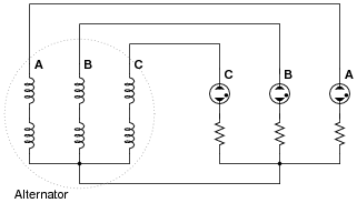
Suppose a set of three neon light bulbs were connected to an alternator with three sets of windings labeled A, B, and C:

|
|
The schematic diagram for this alternator/lamp system is as follows:
|
|
If the alternator spins fast enough (clockwise, as shown), the AC voltage induced in its windings will be enough to cause the neon lamps to "blink" (neon bulbs have very fast reaction times and thus cannot maintain a glow for very long without current, unlike incandescent lamps which operate on the principle of a glowing-hot metal filament). Most likely this blinking will be too fast to discern with the naked eye.
However, if we were to videorecord the blinking and play back the recording at a slow speed, we should be able to see the sequence of light flashes. Determine the apparent "direction" of the lamps' blinking (from right-to-left or from left-to-right), and relate that sequence to the voltage peaks of each alternator coil pair.
Follow-up question: suppose lamp B stopped blinking, while lamps A and C continued. Identify at least two possible causes for this failure.
Notes:
This question is really a prelude to discussing phase rotation in polyphase systems.
Question 6:
What is meant by the term phase rotation sequence, in a polyphase electrical system?
Notes:
Ask your students how the phase rotation sequence of a three-phase system is typically denoted. What symbols are used to describe the direction in which the phase voltages "rotate"?
Question 7:
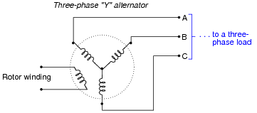
This is a schematic diagram of a Y-connected three-phase generator (with the rotor winding shown):
|
|
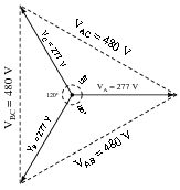
How much AC voltage will appear between any two of the lines (VAB, VBC, or VAC) if each stator coil inside the alternator outputs 277 volts? Draw a phasor diagram showing how the phase (winding) and line voltages relate.
Line voltage = VAB = VBC = VAC = 480 volts AC
|
|
Follow-up question #1: what is the ratio between the line and phase voltage magnitudes in a Y-connected three-phase system?
Follow-up question #2: what would happen to the output of this alternator if the rotor winding were to fail open? Bear in mind that the rotor winding is typically energized with DC through a pair of brushes and slip rings from an external source, the current through this winding being used to control voltage output of the alternator's three-phase ßtator" windings.
Notes:
Students will quickly discover that �3 is the "magic number" for practically all balanced three-phase circuit calculations!
It should be noted that although the magnitudes of VAB, VBC, and VAC are equal, their phasor angles are most definitely not. Therefore,
|
|
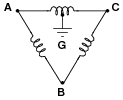
Question 8:
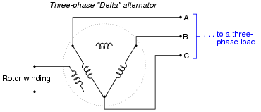
This is a schematic diagram of a Delta-connected three-phase generator (with the rotor winding shown):
|
|
How much AC current will each of the lines (IA, IB, or IC) conduct to a load (not shown) if each stator coil inside the alternator outputs 17 amps of current?
Line current = IA = IB = IC = 29.4 amps AC
Follow-up question #1: what is the ratio between the line and phase current magnitudes in a Delta-connected three-phase system?
Follow-up question #2: what would happen to the output of this alternator if the rotor winding were to fail open? Bear in mind that the rotor winding is typically energized with DC through a pair of brushes and slip rings from an external source, the current through this winding being used to control voltage output of the alternator's three-phase ßtator" windings.
Notes:
Students will quickly discover that �3 is the "magic number" for practically all balanced three-phase circuit calculations!
It should be noted that although the magnitudes of IA, IB, and IC are equal, their phasor angles are most definitely not. Therefore,
|
|
Question 9:
Suppose the electrical power supplied to a commercial building is labeled as "208/120 volt". What does this label mean, exactly? Relate this description to a schematic diagram.
|
|
Notes:
Many students are confused by this when seeing it for the first time. How is it possible to measure voltage between two points in a circuit and obtain 208 volts, when the two series-connected voltage sources between those two points are 120 volts each? Why isn't it 240/120 volts instead?
The answer to this question, of course, is phase shift: the answer to most ßtrange" phenomenon in AC circuits!
Question 10:
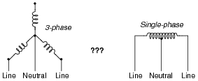
Suppose you are working on the power wiring inside of a home, and are wondering whether or not the home is supplied with 3-phase or single-phase power. You do not have a voltmeter available to measure voltage, but you do have plenty of light bulbs, switches, wires, and other standard residential wiring components available for use.
The two possibilities for this home's power source are shown here, the coils representing secondary windings of the utility power transformer:
|
|
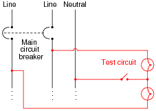
An experienced electrician suggests you build the following circuit to test whether or not the home's power is supplied by a 3-phase source or a single-phase source:
|
|
The electrician tells you to open and close the switch, and observe the brightness of the light bulbs. This will indicate whether or not the system is 3-phase.
Explain how this circuit works. What sort of light bulb behavior would indicate a 3-phase source? What sort of light bulb behavior would indicate a single-phase source?
Notes:
The subject of this question is closely related to the subject of ßingle-phasing" a polyphase load as the result of a line conductor opening. In this case it is the neutral conductor we are intentionally opening, but the results are similar.
Question 11:
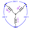
This Delta-connected three-phase power source provides three different voltage levels: 120 V, 208 V, and 240 V. Determine which points of connection provide these voltages:
|
|
VAG = VCG = 120 volts
VBG = 208 volts
Notes:
Despite the fact that this connection scheme is quite common in industry, I have found little reference to it in textbooks. The equilateral layout of the windings in this diagram facilitates graphical (phasor) analysis of the voltages, providing students with the opportunity to exercise their knowledge of trigonometry.
Question 12:
The line voltage to this three-phase load is 480 volts. How much power (total) is dissipated by the load? How much current is there in each line supplying the load?
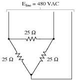
|
|
One more question: write an equation for calculating power in a balanced, three-phase circuit, given line voltage and line current only.
Iline = 33.255 A
I'll let you derive your own equation for power calculation. Be ready to show your work!
Notes:
Now, students will surely be able to find a power equation from textbooks, but the purpose of this question is to have them derive it themselves. In a single-phase, resistive AC circuit, power is given by the equation P = I E, just as in DC circuits. However, if you multiply the line voltage by line current, you do not get the correct answer of 27.648 kW. So, obviously, the equation of P = I E will require some modification for calculating total three-phase power. However, this modification is not complicated to perform.
Question 13:
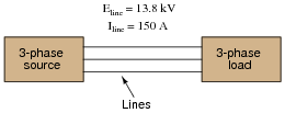
A balanced, three-phase power system has a line voltage of 13.8 kV volts and a line current of 150 amps. How much power is being delivered to the load (assuming a power factor of 1)?
|
|
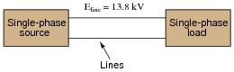
A 13.8 kV single-phase system could be designed to provide the same amount of power to a load, but it would require heavier-gauge (more expensive!) conductors. Determine the extra percentage of expense in wire cost (based on the weight of the wires) resulting from the use of single-phase instead of three-phase.
|
|
A single-phase system operating at 13.8 kV would require at least 1/0 (öne-ought") gauge copper conductors to transmit 3.59 MW of power. A three-phase system operating at the same voltage would require at least #2 gauge copper conductors.
Notes:
This question is good for provoking discussion on the practical, cost-saving benefits of three-phase power systems over single-phase. Your students will have to do some "review" research on wire gauges and weights, but the exercise is well worth it.
Question 14:
Calculate the full-load line current for a three-phase motor, given a horsepower rating of 150 HP, an efficiency of 93%, and a line voltage of 480 volts. Assume a power factor of 0.90 for full-load conditions.
Notes:
Several conversions are necessary to calculate the answer for this question. As usual, the purpose of this question is not so much to obtain an answer, as it is to develop students' problem-solving skills. How did students approach this problem? Did any of them think of ways to simplify the problem so that it could be solved in incremental steps instead of all at once? If so, what was their method(s) of solution?