Design Project: Logic probe
Question 1:
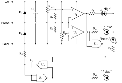
What factors determine where potentiometers Rpot1 and Rpot2 must be set? Why are they "trimmer" potentiometers (as indicated by the special wiper symbol) and not regular panel-mount potentiometers?
Notes:
Do not simply tell your students what these acceptable voltage levels are! Let them research datasheets for instances of logic gates within the logic family desired, and let the manufacturers' data tell them what they need to know.
Question 2:
What performance parameters are important to consider for U1 and U2, considering their use in a logic probe circuit? Hint: we may want to use this logic probe to troubleshoot CMOS as well as TTL circuits.
Notes:
Note how the comparators sink current from the LEDs rather than source current to them. This design feature was necessary, due to the construction of the LM339. In fact, there are a lot of comparators that can only sink current and not source current due to the internal use of an open-collector output stage.
Question 3:
What purpose do resistors R1 and R2 serve, and why are they so large (1,000,000 ohms each)?
Notes:
A less obvious feature of these resistors is that they force the circuit under test to drive a bit of current to (or from) the probe. This is good, as it may help to show a gate with a "weak" output, such as one that is mildly overloaded. Lower values for R1 and R2 would accentuate this feature, but would also make it trickier to set the high/low threshold potentiometers (Rpot1 and Rpot2).
Another not-so-obvious design feature is that resistors R1 and R2 establish a default input voltage level that is between the two threshold settings established by the potentiometers. In my first design, I connected R1 and R2 to the power supply rails, respectively. This set the default (floating) input voltage at 1/2 V, which worked fine for CMOS logic levels but not for TTL. By having the resistors set a default input voltage between the two threshold adjustments, a floating probe is guaranteed to indicate ïndeterminate" no matter where the threshold potentiometers are set.
Question 4:
Re-design the example circuit so that a NAND logic gate is not required. Instead, think of a way you could use discrete components to do the same job.
Notes:
Not only will a discrete transistor have a wider voltage range it can operate over (compared to a logic gate), but it is a good review of transistor circuit theory and a practical example of implementing a simple logic function without the benefit of integrated circuits.
Question 5:
An extra feature you could add to the logic probe circuit is a pulse indication LED. This LED momentarily turns on whenever there is a transition from high-to-low or from low-to-high:
|
|
Actually, what the pulse indicator circuit detects is a transition to the ïndeterminate" state, which always lies between "high" and "low." A pulse indication feature is nice to have in some circumstances, since it shows the presence of pulses which may be too brief to light up either the "high" or "low" LED. The two additional NAND gates ßtretch" the pulse time so that the "pulse" LED's blink is long enough to see. The duration of the LED's blink is set by resistor R7 and capacitor C2.
Explain how the pulse indication circuitry works.
Notes:
I recommend a 0.47 mF capacitor for C2 and a 100 kW resistor for R7. The added feature of a pulse indicator LED is particularly nice because it makes use of what would otherwise be unused gates in a 4011 CMOS NAND gate IC. The only added componentry is the fourth LED, current limiting resistor R6, capacitor C2, and resistor R7.