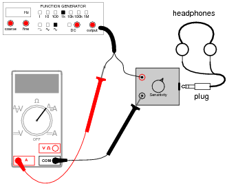
Design Project: Sensitive audio detector
Question 1:
The choice of step-down transformers to use in a project such as this is not arbitrary. We must consider several factors when choosing a particular transformer:
- �
- Turns ratio
- �
- Winding voltage rating(s)
- �
- Isolation (safety) voltage rating
- �
- Expense (transformers can be expensive!)
A turns ratio between 20:1 and 10:1 seems to work good for a project such as this. I recommend a transformer with a highest high-voltage winding rating and winding-to-winding isolation possible, to provide maximum resistance between the circuit under test (primary) and your headphones (secondary). This is a safety feature - to ensure that you will not receive an electric shock if the detector is accidently connected to a source of lethal voltage. I also recommend using a recycled transformer (i.e. salvaged from some junk equipment) rather than purchasing a new one.
Identify some commonly available transformers that fit these criteria.
Of course, plain 1000:8 ohm audio matching transformers will function adequately as far as signal detection is concerned. However, these transformers typically do not provide the same level of winding-to-winding isolation that a power transformer will, and so I do not recommend them for permanent construction (only for proof-of-concept circuits).
NOTE: be sure to observe all appropriate safety precautions if salvaging transformers from old equipment, especially high-voltage devices such as microwave ovens! If unsure of anything, consult your instructor before proceeding with the disassembly of a device. Many pieces of electronic equipment contain high-voltage capacitors which may store lethal charges long after the device has been powered. All capacitors must be discharged in a reasonable manner prior to touching conductors in old equipment!
Notes:
Make sure your students do some actual research in arriving at their suggested transformer sources - simply repeating what they read in the answer is not acceptable.
It may seem odd to suggest the use of line-frequency power transformers for this purpose, where the (audio) signal frequency range may far exceed 60 Hz. However, we are not aiming for high fidelity with this device, only maximum sensitivity and maximum safety. Incidentally, I have found that AC line power transformers - when operated at voltages far below their winding ratings - do a decent job of audio signal reproduction because the magnetic field flux in the core is so incredibly low compared to what would be there transforming 50 Hz or 60 Hz line power. The fidelity of an audio signal intercepted from a radio circuit with this detector, for example, is quite satisfactory for diagnostic purposes.
Question 2:
The series resistances and parallel-connected diodes in this circuit act as a voltage clipping network. Why do you suppose it would be important to limit, or "clip," the signal voltage before it reaches the rest of the circuitry? The detector will function adequately without the diodes or resistors in place, so why are they there?
Notes:
Your students may not yet be familiar with the operation of semiconductor diodes. For now, just explain that diodes only conduct current in one direction, and even then they do not begin to conduct until the voltage drop across them is approximately 0.7 volts (for silicon diodes).
Question 3:
Can this detector be used to indicate the presence of direct current (DC), or only AC within the audio frequency range? How about AC signals beyond the audio frequency range?
Notes:
Have your students share their successes with signal detection above and below the audio frequency range. What technique(s) yielded the best (most sensitive) results?
Question 4:
With the headphones connected to the input of your audio detector circuit, what is the lowest current level of signal you can hear, as measured with a sensitive milliammeter connected in series between your detector and a signal source?

|
|
Compare this against the lowest amount of audible signal current for the headphones directly. Which component of the detector circuit is responsible for this increased sensitivity?
Notes:
This is a very practical way for students to experience the significance of impedance matching using transformers.
Question 5:
Suppose I wish to listen to the "hum" of ripple voltage from an AC-to-DC power supply using this detector. "Ripple voltage," in case you don't know, is a small AC voltage superimposed on a large DC voltage. If I simply connect my detector directly to the power supply's terminals, I hear a LOUD "click." If I turn the volume control down until the "click" is tolerable, the hum is too faint to hear. If I turn the volume control up far enough to hear the hum, then the "click" is far too loud for comfort.
How can I set up the detector so that it only detects the AC portion (the "ripple" voltage) of the power supply's output, and not the DC portion?
Follow-up question: modify the schematic diagram to include an AC/DC coupling switch, so the detector's coupling may be switched from one mode to the other just like an oscilloscope.
Notes:
It would be very helpful to have an AC-DC power supply with substantial ripple voltage available for students to do this exercise.
