Fundamentals of radio communication
Question 1:
What does the acronym RF stand form, in reference to radio-related electronics?
Notes:
Ask your students to list the frequencies of their favorite broadcast radio stations as an example of some radio frequencies. Show them a typical benchtop signal generator (non-RF) for comparison of frequency range, and they should begin to understand the concept.
Question 2:
We know at this point that any circuit comprised of inductance (L) and capacitance (C) is capable of resonating: attaining large values of AC voltage and current if ëxcited" at the proper frequency. The so-called tank circuit is the simplest example of this:

|
|
The less resistance (R) such a circuit has, the better its ability to resonate.
We also know that any piece of wire contains both inductance and capacitance, distributed along its length. These properties are not necessarily intentional - they exist whether we would want them to or not:
|
|
Given that the electrical resistance of a continuous piece of metal wire is usually quite low, describe what these natural properties of inductance and capacitance mean with regard to that wire's function as an electrical element.
Follow-up question: qualitatively estimate the frequency you suppose a length of wire would resonate at. Do you think fr would be a very low value (tens of hertz), a very high value (thousands, millions, or billions of hertz), or somewhere in between? Keep in mind the equation for resonant frequency:
|
Notes:
If your students have difficulty knowing where to start with the follow-up question, ask them to qualitatively estimate the distributed L and C for a piece of wire, say, 10 feet long. Given the lack of any high-permeability core material and the lack of any high-permittivity dielectric (just air), the answers for both should be "very small." Then, ask them again how they would qualitatively rate the wire's resonant frequency.
Question 3:
Shown here is a simple quarter-wave antenna, comprised of a single wire projecting vertically from one terminal of an RF voltage source, the other terminal connected to earth ground:
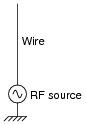
|
|
Re-draw this illustration, showing the equivalent inductance and capacitance exhibited by this antenna. Show these properties using actual inductor and capacitor symbols.
|
|
Follow-up question: how would you expect the inductance and capacitance of this antenna to relate to its physical length? In other words, as you increase the length of an antenna, would its inductance increase or decrease? As the length increases, would its capacitance increase or decrease? Explain your reasoning.
Notes:
Do not be surprised if some of your students ask whether or not an antenna is capable of resonating, since it possesses both inductance and capacitance. In fact, this is the subversive point of this question: to get students to realize that even a simple pair of wires may be considered a resonant system, and then to beg the question of what happens at resonance! The follow-up question suggests a relationship between physical size and resonant frequency, by asking what happens to both L and C as length changes. Explore these ideas with your students, and watch them gain a surprisingly deep understanding of how an antenna works based on their knowledge of LC resonant circuits.
Question 4:
Shown here is a simple dipole antenna, comprised of two equal-length wires projecting from the terminals of an RF voltage source:

|
|
Re-draw this illustration, showing the equivalent inductance and capacitance exhibited by this antenna. Show these properties using actual inductor and capacitor symbols.
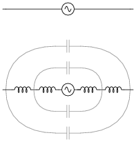
|
|
Follow-up question: how would you expect the inductance and capacitance of this antenna to relate to its physical length? In other words, as you increase the length of an antenna, would its inductance increase or decrease? As the length increases, would its capacitance increase or decrease? Explain your reasoning.
Notes:
Do not be surprised if some of your students ask whether or not an antenna is capable of resonating, since it possesses both inductance and capacitance. In fact, this is the subversive point of this question: to get students to realize that even a simple pair of wires may be considered a resonant system, and then to beg the question of what happens at resonance! The follow-up question suggests a relationship between physical size and resonant frequency, by asking what happens to both L and C as length changes. Explore these ideas with your students, and watch them gain a surprisingly deep understanding of how an antenna works based on their knowledge of LC resonant circuits.
Question 5:
A Scottish physicist named James Clerk Maxwell made an astonishing theoretical prediction in the nineteenth century, which he expressed with these two equations:
|
|
The first equation states that an electric field (E) will be produced in open space by a changing magnetic flux ([(d FB)/dt]). The second equation states than a magnetic field (B) will be produced in open space either by an electric current (I) or by a changing electric flux ([(d FE)/dt]). Given this complementary relationship, Maxwell reasoned, it was possible for a changing electric field to create a changing magnetic field which would then create another changing electric field, and so on. This cause-and-effect cycle could continue, ad infinitum, with fast-changing electric and magnetic fields radiating off into open space without needing wires to carry or guide them. In other words, the complementary fields would be self-sustaining as they traveled.
Explain the significance of Maxwell's prediction, especially as it relates to electronics.
Follow-up question: name the scientist who first experimentally confirmed Maxwell's prediction of electromagnetic waves.
Notes:
Not only does this question relate the concept of radio waves to concepts your students should already be familiar with (electric and magnetic fields), but it also introduces a piece of amazing scientific history. That radio waves were first predicted mathematically rather than discovered accidently by experiment is both astonishing and enlightening.
You may find that one or more of your brighter students notice Maxwell's prediction relates a change in one type of field to a static magnitude of the other (i.e. E � [(dFB)/dt] and B � [(dFE)/dt]), and that this makes it difficult to see how one changing field could create another changing field. If anyone asks this question, point out to them that there is a set of similar mathematical functions related to one another by derivatives, and they are:
|
Does anything look familiar (omitting the m0 I term from the second equation)?
|
Since we know electric flux is related to electric field by geometry (FE = �E ·dA) and magnetic flux is related to magnetic field by geometry as well (FB = �B ·dA), we may write the following proportionalities:
|
Now do things look similar to the sine/cosine derivative relationship? Thus, if the electric flux FE oscillates as a sine wave, the magnetic flux FB will oscillate as a cosine wave, and so on.
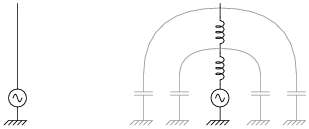
Question 6:
In 1887, a German physicist named Heinrich Hertz successfully demonstrated the existence of electromagnetic waves. Examine the following schematic of the apparatus he used to do this, and explain what significance Hertz's discovery has to do with your study of electronics:
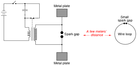
|
|
Notes:
An experiment such as this is not difficult to set up. Be sure to provide the appropriate safety precautions against electric shock, as such spark-gap transmitters (as they came to be called) require substantially high voltages to operate.
Question 7:
Given James Clerk Maxwell's prediction of electromagnetic waves arising from the self-sustenance of changing electric and magnetic fields in open space, what sort of a device or collection of devices do you think we would need to create electromagnetic waves oscillating at a frequency within the range attainable by an electric circuit? In other words, what kind of component(s) would we attach to a source of high-frequency AC to radiate these waves?
Notes:
The purpose of this question is to relate the concept of distributed capacitance and inductance along a plain piece of wire to the very nature of electromagnetic waves (oscillating electric and magnetic fields). If students suggest using capacitors and inductors, they are quite close to the mark. Unfortunately, these devices are usually designed to contain their respective fields to prevent radiation into space. Here, we want the fields to radiate away from the device, and so we use an open wire (or an array of open wires).
Question 8:
Although radio transmitter antennae ideally possesses only inductance and capacitance (no resistance), in practice they are found to be very dissipative. In other words, they tend to act as large resistors to the transmitters they are connected to. Explain why this is. In what form is the dissipated energy manifest (heat, light, or something else)?
Notes:
Although students may have some to associate the concept of "dissipation" exclusively with resistors, this is not entirely correct. All that is meant by "dissipation" is the dispersal of energy; that is, energy leaving an electric circuit and not returning. With resistors, this occurs in the form of heat, but this is not the only kind of dissipation! In electric motors, most of the energy is dissipated in the form of mechanical energy, which goes into doing work (and some heat, of course). Light bulbs dissipate energy in the form of light, not just heat.
Question 9:
A crystal goblet may be shattered if exposed to high-intensity sound. Less volume is required to shatter the goblet if the sound is at such a frequency that it resonates with the goblet's natural frequency. That is, there will be maximum transfer of energy to the goblet if the sound waves are transmitted at precisely the goblet's resonant frequency.
How does this phenomenon relate to the reception of radio waves, since we know that a radio antenna effectively acts as a resonant LC (inductance/capacitance) network?
Notes:
The analogy of a goblet shattered by sound waves helps students readily identify with a concept that is otherwise abstract: the reception of electromagnetic waves by an antenna. Ask your students to relate the matching of frequencies to the transmission of radio waves as well as the reception of them.
Question 10:
Radio waves are comprised of oscillating electric and magnetic fields, which radiate away from sources of high-frequency AC at (nearly) the speed of light. An important measure of a radio wave is its wavelength, defined as the distance the wave travels in one complete cycle.
Suppose a radio transmitter operates at a fixed frequency of 950 kHz. Calculate the approximate wavelength (l) of the radio waves emanating from the transmitter tower, in the metric distance unit of meters. Also, write the equation you used to solve for l.
I'll let you find the equation on your own!
Notes:
I purposely omit the velocity of light, as well as the time/distance/velocity equation, so that students will have to do some simple research this calculate this value. Neither of these concepts is beyond high-school level science students, and should pose no difficulty at all for college-level students to find on their own.
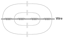
Question 11:
A radio antenna possesses both parasitic capacitance and distributed inductance, distributed along its entire length:
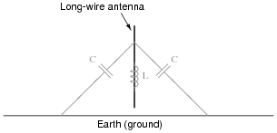
|
|
Ideally, an antenna only exhibits these electrical properties, with no resistance. What does this suggest about the electrical behavior of an antenna, especially compared to the behavior of other LC circuits you are familiar with?
Follow-up question: what physical variable(s) determines the resonant frequency of an antenna?
Notes:
It is important for students to be able to relate new information to that which they already understand. By likening an antenna to an LC (resonant) circuit, students should be able to predict something about the behavior of antennae, and why it is important to match an antenna to the frequency of transmission.
Question 12:
When performing tests on a radio transmitter, it is often necessary to do so without actually broadcasting a signal through an antenna. In such scenarios, an equivalent resistor is connected to the output of the transmitter instead of an actual antenna. If chosen properly, the resistor "looks" the same as an antenna from the perspective of the transmitter.
Explain how this is possible, since real antennae are built to have as little resistance as possible. How can a resistor adequately substitute for an antenna, which is nothing like a resistor in either construction or purpose?
Notes:
Ask your students what criteria they think a resistor needs to meet in order to properly serve as a "dummy" antenna. Discuss impedance, Q factor, power rating, etc.
Question 13:
Calculate the theoretical length for a "half-wave" antenna, assuming a transmitter "carrier" frequency of 105.3 MHz:
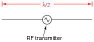
|
|
Also, calculate the practical antenna length considering the ënd effect," which makes the antenna's electrical length slightly different from its physical length (assume a K factor of 0.95).
([(l)/2])practical = 1.353 meters
Notes:
Here, students must understand the mathematical relationship between antenna length and operating frequency, both theoretical and practical.