Rectifier circuits
Question 1:
| Don't just sit there! Build something!! |
Learning to mathematically analyze circuits requires much study and practice. Typically, students practice by working through lots of sample problems and checking their answers against those provided by the textbook or the instructor. While this is good, there is a much better way.
You will learn much more by actually building and analyzing real circuits, letting your test equipment provide the änswers" instead of a book or another person. For successful circuit-building exercises, follow these steps:
- 1.
- Carefully measure and record all component values prior to circuit construction, choosing resistor values high enough to make damage to any active components unlikely.
- 2.
- Draw the schematic diagram for the circuit to be analyzed.
- 3.
- Carefully build this circuit on a breadboard or other convenient medium.
- 4.
- Check the accuracy of the circuit's construction, following each wire to each connection point, and verifying these elements one-by-one on the diagram.
- 5.
- Mathematically analyze the circuit, solving for all voltage and current values.
- 6.
- Carefully measure all voltages and currents, to verify the accuracy of your analysis.
- 7.
- If there are any substantial errors (greater than a few percent), carefully check your circuit's construction against the diagram, then carefully re-calculate the values and re-measure.
When students are first learning about semiconductor devices, and are most likely to damage them by making improper connections in their circuits, I recommend they experiment with large, high-wattage components (1N4001 rectifying diodes, TO-220 or TO-3 case power transistors, etc.), and using dry-cell battery power sources rather than a benchtop power supply. This decreases the likelihood of component damage.
As usual, avoid very high and very low resistor values, to avoid measurement errors caused by meter "loading" (on the high end) and to avoid transistor burnout (on the low end). I recommend resistors between 1 kW and 100 kW.
One way you can save time and reduce the possibility of error is to begin with a very simple circuit and incrementally add components to increase its complexity after each analysis, rather than building a whole new circuit for each practice problem. Another time-saving technique is to re-use the same components in a variety of different circuit configurations. This way, you won't have to measure any component's value more than once.
Notes:
It has been my experience that students require much practice with circuit analysis to become proficient. To this end, instructors usually provide their students with lots of practice problems to work through, and provide answers for students to check their work against. While this approach makes students proficient in circuit theory, it fails to fully educate them.
Students don't just need mathematical practice. They also need real, hands-on practice building circuits and using test equipment. So, I suggest the following alternative approach: students should build their own "practice problems" with real components, and try to mathematically predict the various voltage and current values. This way, the mathematical theory "comes alive," and students gain practical proficiency they wouldn't gain merely by solving equations.
Another reason for following this method of practice is to teach students scientific method: the process of testing a hypothesis (in this case, mathematical predictions) by performing a real experiment. Students will also develop real troubleshooting skills as they occasionally make circuit construction errors.
Spend a few moments of time with your class to review some of the "rules" for building circuits before they begin. Discuss these issues with your students in the same Socratic manner you would normally discuss the worksheet questions, rather than simply telling them what they should and should not do. I never cease to be amazed at how poorly students grasp instructions when presented in a typical lecture (instructor monologue) format!
A note to those instructors who may complain about the "wasted" time required to have students build real circuits instead of just mathematically analyzing theoretical circuits:
What is the purpose of students taking your course?
If your students will be working with real circuits, then they should learn on real circuits whenever possible. If your goal is to educate theoretical physicists, then stick with abstract analysis, by all means! But most of us plan for our students to do something in the real world with the education we give them. The "wasted" time spent building real circuits will pay huge dividends when it comes time for them to apply their knowledge to practical problems.
Furthermore, having students build their own practice problems teaches them how to perform primary research, thus empowering them to continue their electrical/electronics education autonomously.
In most sciences, realistic experiments are much more difficult and expensive to set up than electrical circuits. Nuclear physics, biology, geology, and chemistry professors would just love to be able to have their students apply advanced mathematics to real experiments posing no safety hazard and costing less than a textbook. They can't, but you can. Exploit the convenience inherent to your science, and get those students of yours practicing their math on lots of real circuits!
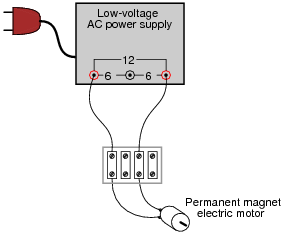
Question 2:
What would this permanent-magnet DC motor do, if powered by a source of AC voltage?
|
|
Notes:
Discuss this phenomenon with your students. Ask them whether they know of any other "polarized" (DC-only) devices. Ask them what they think would be necessary to make a DC-only device function on AC power.
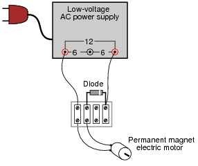
Question 3:
What would this permanent-magnet DC motor do, if powered by the following circuit?
|
|
Follow-up question: identify the polarity of the DC voltage between the motor terminals.
Notes:
Ask your students why the motor's torque pulsates instead of being steady as it would be when powered by a battery. Is this necessarily a bad thing? How does the motor's speed compare with being powered by a DC source of the same (RMS-equivalent) voltage?
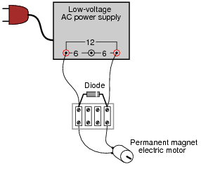
Question 4:
What would this permanent-magnet DC motor do, if powered by the following circuit?
|
|
Follow-up question: identify the polarity of the DC voltage between the motor terminals, during that brief period of time where all component are still functioning.
Notes:
Ask your students why this circuit is self-destructive. If it functions as a rectifier for powering the DC motor for a short period of time, then why doesn't it function that way for an indefinite period of time?
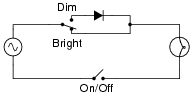
Question 5:
Some inexpensive household lamps use a diode to achieve two-position light control (dim and bright):
|
|
Explain how this circuit is able to make the light bulb glow brighter and dimmer.
Follow-up question: does it matter which way the diode is oriented in the circuit? If we reversed its connections, would the light bulb behave any differently?
Notes:
Although this circuit is not very complex, it reveals an application of diode rectification often overlooked: power control for non-polarized loads. Ask your students how the energy efficiency of a circuit like this compares to a rheostat (resistive) light dimming circuit.
Question 6:
Trace the flow of all currents in this half of the AC cycle (note the polarity symbols near the transformer's primary winding terminals):
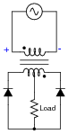
|
|
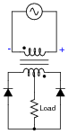
Now, trace the flow of all currents in the other half of the AC cycle (note the polarity symbols near the transformer's primary winding terminals):
|
|
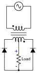
Also, determine the polarity of DC voltage across the load resistor.
|
|
Notes:
This question not only introduces a type of full-wave rectifying circuit, but it also serves as a good review of transformer action and winding phase markings. I have omitted diagrams showing direction of currents in this circuit, partly because they may be ascertained by way of the load resistor's voltage polarity (shown in the answer), and partly because I'd rather not have to choose between giving an answer in conventional flow notation versus electron flow notation.
Question 7:
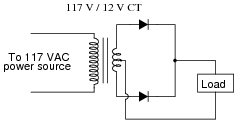
In this rectifier circuit, the output voltage is less than half of the secondary winding's rated voltage (12 volts). Why is this?
|
|
Also, determine whether this is a half-wave or a full-wave rectifier circuit, and explain your answer.
This is a full-wave rectifier circuit.
Challenge question: what would have to change in this circuit to make it a half-wave rectifier?
Notes:
If this question is confusing to some students, take time to discuss the directions of all currents in the circuit through both halves of the AC cycle. Then, the answer should be apparent.
Question 8:
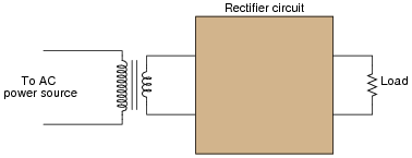
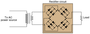
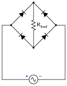
A very common form of full-wave rectifier circuit is the bridge rectifier. Typically, it is drawn as a "diamond" of four diodes:
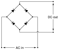
|
|
Draw the connections in this illustration to form a bridge rectifier circuit, receiving power from the transformer and delivering power to the light bulb:
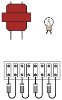
|
|
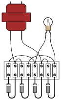
|
|
Follow-up question: draw the direction of currents through the bridge rectifier for each half-cycle of the AC power source, and determine the DC voltage polarity across the light bulb terminals.
Notes:
Realistic connection problems such as this are much easier to solve in the presence of a schematic diagram. If you have students who struggle with this question, make sure they take the time to draw a schematic first. Finding a schematic diagram of a full-wave bridge rectifier circuit to copy is no challenge at all. As a rule, I do not offer assistance to students with questions until they have at least taken this first step, because so often they end up answering their own questions in the process of drawing a schematic diagram!
Question 9:
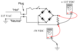
Determine the approximate amount of voltage that each voltmeter in this circuit will indicate:
|
|
|
|
Challenge question: how could the 58 volts from (-) to ground be eliminated, so as to permit grounding of the (-) output terminal?
Notes:
Direct rectification of a grounded AC power source results in significant voltage being dropped between either DC output conductor and ground. Ask your students what kinds of problems might be caused by this effect. How about safety? Ask them if they think 58 volts presents a safety hazard.
In answer to the challenge question, what is needed here is some kind of electrical isolation. There is more than one answer to this problem, but definitely one solution that is more popular than the others.
Question 10:
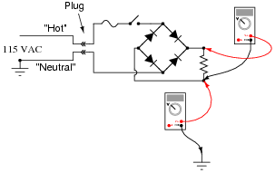
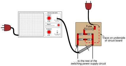
A technician decides to measure the output voltage of a bridge rectifier circuit using an oscilloscope. This particular bridge rectifier is the front-end of a switching power supply circuit, and directly rectifies the incoming 120 volt AC power, with no transformer:
|
|
However, the technician is surprised to find that the fuse blows every time she turns the power on to the circuit. When the oscilloscope is disconnected from the circuit, the fuse does not blow, and everything works fine. What is wrong? Why does the oscilloscope cause a fault in the circuit?
Here is another interesting piece of information: if just the probe tip is touched to one of the rectifier circuit's output terminals, the oscilloscope shows a half-wave rectified waveform, without the ground clip being connected to anything!
Notes:
The answer given here does not reveal everything. The student still must determine why grounding one of the rectifier circuit's output terminals results in a ground fault that blows the fuse. The observation of a half-wave signal with just the probe tip touching the circuit is the big hint in this question.
Question 11:
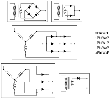
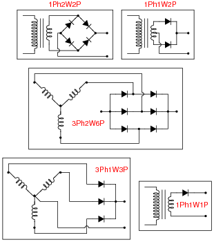
Power rectifier circuits are often classified according to their number of phases, ways, and pulses. Match the following rectifier circuits to the Phase/Way/Pulse labels given in this illustration:
|
|
|
|
Notes:
The meaning of these labels can be confusing, so be sure to discuss them thoroughly with your students. Have them tell you what "Phases," "Ways," and "Pulses" mean, using their own words.
Question 12:
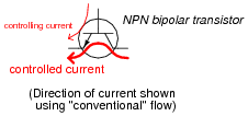
Bipolar transistors are extremely useful devices, allowing a small electric current to control the flow of a much larger electric current:
|
|
These devices would be even more useful to us if they were able to control alternating current (AC), but they cannot. Bipolar transistors are polarized (one-way-only) devices.
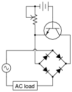
This fact does not prevent us from using bipolar transistors to control AC. We just have to be clever about how we do it:
|
|
Explain how this circuit functions. How is the transistor (a DC-only device) able to control alternating current (AC) through the load?
Notes:
Usually, rectifier circuits are thought of exclusively as intermediary steps between AC and DC in the context of an AC-DC power supply. They have other uses, though, as demonstrated by this interesting circuit!
It should be of no consequence if students have not yet studied transistors. In fact, it is a good thing to give them a very brief introduction to the function of a previously unknown component and then have them examine a circuit (the rest of which they should understand well) to ascertain an overall function. This is sometimes called the "Black Box" approach in engineering, and it is necessary when working around state-of-the-art electronic equipment, where you are practically guaranteed not to understand the inner workings of every subsystem and component.
Question 13:
Suppose you need to build a full-wave bridge rectifier with a current rating of 2.5 amps, but only have model 1N4001 diodes to build it with. Draw a schematic diagram of the circuit, showing how multiple 1N4001 diodes could be connected together to accomplish this:
|
|
|
|
Follow-up question: while this circuit should work (in theory), in practice one or more of the diodes will fail prematurely due to overheating. The fix for this problem is to connect ßwamping" resistors in series with the diodes like this:
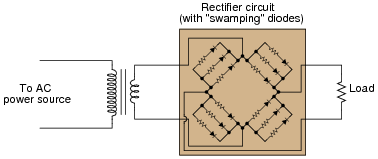
|
|
Explain why these resistors are necessary to ensure long diode life.
Notes:
The answer to this question should not be much of a challenge to your students, although the follow-up question is a bit challenging. Ask your students what purpose the swamping resistors serve in this circuit. What do we know about current through the diodes if one or more of them will fail due to overheating without the swamping resistors?
What value of resistor would your students recommend for this application? What factors influence their decision regarding the resistance value?
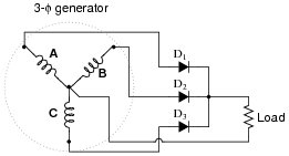
Question 14:
Predict how all component voltages and currents in this circuit will be affected as a result of the following faults. Consider each fault independently (i.e. one at a time, no multiple faults):
|
|
- �
- Diode D1 fails open:
- �
- Generator winding C fails open:
- �
- Center connection joining generator windings fails open:
For each of these conditions, explain why the resulting effects will occur.
- �
- Diode D1 fails open: Load receives 2-pulse rectification instead of 3-pulse, increased voltage across D1.
- �
- Generator winding C fails open: Load receives 2-pulse rectification instead of 3-pulse, no current through D3.
- �
- Center connection joining generator windings fails open: No voltage across any diode or across load, no current through any diode or through load.
Notes:
The purpose of this question is to approach the domain of circuit troubleshooting from a perspective of knowing what the fault is, rather than only knowing what the symptoms are. Although this is not necessarily a realistic perspective, it helps students build the foundational knowledge necessary to diagnose a faulted circuit from empirical data. Questions such as this should be followed (eventually) by other questions asking students to identify likely faults based on measurements.
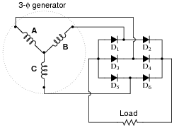
Question 15:
Predict how all component voltages and currents in this circuit will be affected as a result of the following faults. Consider each fault independently (i.e. one at a time, no multiple faults):
|
|
- �
- Diode D3 fails open:
- �
- Generator winding C fails open:
- �
- Center connection joining generator windings fails open:
For each of these conditions, explain why the resulting effects will occur.
- �
- Diode D3 fails open: Load receives 5-pulse rectification instead of 6-pulse, increased voltage across D3.
- �
- Generator winding C fails open: Load receives 2-pulse rectification instead of 6-pulse, no current through D5 or D6.
- �
- Center connection joining generator windings fails open: No voltage across any diode or across load, no current through any diode or through load.
Notes:
The purpose of this question is to approach the domain of circuit troubleshooting from a perspective of knowing what the fault is, rather than only knowing what the symptoms are. Although this is not necessarily a realistic perspective, it helps students build the foundational knowledge necessary to diagnose a faulted circuit from empirical data. Questions such as this should be followed (eventually) by other questions asking students to identify likely faults based on measurements.
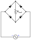
Question 16:
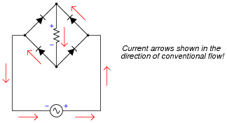
Trace the current through this rectifier circuit at a moment in time when the AC source's polarity is positive on right and negative on left as shown. Be sure to designate the convention you use for current direction (conventional or electron flow):
|
|
Also, mark the polarity of the voltage drop across Rload.
|
|
Notes:
Have your students explain their reasoning when tracing currents and determining voltage drop polarities in front of the class for all too see. The bridge rectifier circuit is one that many students find confusing to analyze, and so it is worth spending time on in class to fully understand.
Question 17:
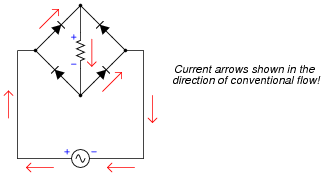
Trace the current through this rectifier circuit at a moment in time when the AC source's polarity is positive on left and negative on right as shown. Be sure to designate the convention you use for current direction (conventional or electron flow):
|
|
Also, mark the polarity of the voltage drop across Rload.
|
|
Notes:
Have your students explain their reasoning when tracing currents and determining voltage drop polarities in front of the class for all too see. The bridge rectifier circuit is one that many students find confusing to analyze, and so it is worth spending time on in class to fully understand.