Basic electromagnetic relays
Question 1:
| Don't just sit there! Build something!! |
Learning to analyze relay circuits requires much study and practice. Typically, students practice by working through lots of sample problems and checking their answers against those provided by the textbook or the instructor. While this is good, there is a much better way.
You will learn much more by actually building and analyzing real circuits, letting your test equipment provide the änswers" instead of a book or another person. For successful circuit-building exercises, follow these steps:
- 1.
- Draw the schematic diagram for the relay circuit to be analyzed.
- 2.
- Carefully build this circuit on a breadboard or other convenient medium.
- 3.
- Check the accuracy of the circuit's construction, following each wire to each connection point, and verifying these elements one-by-one on the diagram.
- 4.
- Analyze the circuit, determining all logic states for given input conditions.
- 5.
- Carefully measure those logic states, to verify the accuracy of your analysis.
- 6.
- If there are any errors, carefully check your circuit's construction against the diagram, then carefully re-analyze the circuit and re-measure.
Always be sure that the power supply voltage levels are within specification for the relay coils you plan to use. I recommend using PC-board relays with coil voltages suitable for single-battery power (6 volt is good). Relay coils draw quite a bit more current than, say, semiconductor logic gates, so use a "lantern" size 6 volt battery for adequate operating life.
One way you can save time and reduce the possibility of error is to begin with a very simple circuit and incrementally add components to increase its complexity after each analysis, rather than building a whole new circuit for each practice problem. Another time-saving technique is to re-use the same components in a variety of different circuit configurations. This way, you won't have to measure any component's value more than once.
Notes:
It has been my experience that students require much practice with circuit analysis to become proficient. To this end, instructors usually provide their students with lots of practice problems to work through, and provide answers for students to check their work against. While this approach makes students proficient in circuit theory, it fails to fully educate them.
Students don't just need mathematical practice. They also need real, hands-on practice building circuits and using test equipment. So, I suggest the following alternative approach: students should build their own "practice problems" with real components, and try to predict the various logic states. This way, the relay theory "comes alive," and students gain practical proficiency they wouldn't gain merely by solving Boolean equations or simplifying Karnaugh maps.
Another reason for following this method of practice is to teach students scientific method: the process of testing a hypothesis (in this case, logic state predictions) by performing a real experiment. Students will also develop real troubleshooting skills as they occasionally make circuit construction errors.
Spend a few moments of time with your class to review some of the "rules" for building circuits before they begin. Discuss these issues with your students in the same Socratic manner you would normally discuss the worksheet questions, rather than simply telling them what they should and should not do. I never cease to be amazed at how poorly students grasp instructions when presented in a typical lecture (instructor monologue) format!
A note to those instructors who may complain about the "wasted" time required to have students build real circuits instead of just mathematically analyzing theoretical circuits:
What is the purpose of students taking your course?
If your students will be working with real circuits, then they should learn on real circuits whenever possible. If your goal is to educate theoretical physicists, then stick with abstract analysis, by all means! But most of us plan for our students to do something in the real world with the education we give them. The "wasted" time spent building real circuits will pay huge dividends when it comes time for them to apply their knowledge to practical problems.
Furthermore, having students build their own practice problems teaches them how to perform primary research, thus empowering them to continue their electrical/electronics education autonomously.
In most sciences, realistic experiments are much more difficult and expensive to set up than electrical circuits. Nuclear physics, biology, geology, and chemistry professors would just love to be able to have their students apply advanced mathematics to real experiments posing no safety hazard and costing less than a textbook. They can't, but you can. Exploit the convenience inherent to your science, and get those students of yours practicing their math on lots of real circuits!
Question 2:
What is an electromechanical relay?
Notes:
If your students do not know what a ßolenoid" is, this question is an excellent opportunity to find out!
Question 3:
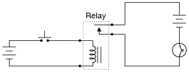
What will happen when the pushbutton switch is actuated in this circuit?
|
|
Follow-up question: is the contact inside the relay normally-open or is it normally-closed?
Notes:
There is a sequence of events to the final result of the pushbutton's actuation. Be sure to ask you students to explain all the steps, from beginning to end, of this relay circuit's operation. Test their comprehension of this circuit, to ensure they fully understand what is taking place.
A logical question your students may ask is, "What is the point?" After all, a circuit with no relay at all (just a switch, battery, and lamp) could accomplish the same task! What is the point of having an extra battery and this device called a relay? Resist the temptation to tell them why, and let them figure out some possible reasons for using a relay.
Question 4:
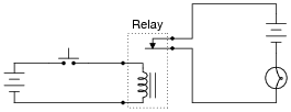
What will happen when the pushbutton switch is actuated in this circuit?
|
|
Follow-up question: is the contact inside the relay normally-open or is it normally-closed?
Notes:
There is a sequence of events to the final result of the pushbutton's actuation. Be sure to ask you students to explain all the steps, from beginning to end, of this relay circuit's operation. Test their comprehension of this circuit, to ensure they fully understand what is taking place.
A logical question your students may ask is, "What is the point?" After all, a circuit with no relay at all (just a switch, battery, and lamp) could accomplish the same task! What is the point of having an extra battery and this device called a relay? Resist the temptation to tell them why, and let them figure out some possible reasons for using a relay.
Question 5:
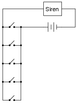
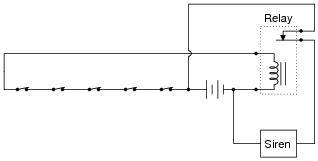
Suppose an engineer designed a fire alarm system for a large warehouse, with multiple pushbutton switches connected to a single alarm siren:
|
|
Actuating any of the normally-open switches results in the alarm sounding. So far, so good.
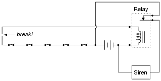
Now, suppose that one of the wires connecting one side of several switches to the rest of the circuit breaks open. What will the result of this failure be?
|
|
Notes:
The immediate and obvious conclusion is that four out of the five switches will be non-functional. However, it isn't this consequence in itself that is the greatest problem. Rather, it is the silence of the failure - no one knows anything has failed, until they try to use one of the non-functional switches! Ask your students to explain what the essential nature of the problem is: what is it about this circuit's operation that makes an öpen" failure in the field wiring so dangerously inconspicuous?
Question 6:
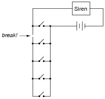
Suppose an engineer designed a fire alarm system for a large warehouse, with multiple pushbutton switches connected to a single alarm siren:
|
|
Actuating any of the normally-closed switches results in the alarm sounding. So far, so good.
Now, suppose that one of the wires connecting one side of several switches to the rest of the circuit breaks open. What will the result of this failure be?
|
|
Notes:
Ask your students what essential task the relay performs in this system. Is there any way to build this circuit to have the same functionality without using a relay?
Question 7:
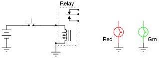
Complete the schematic diagram for a SPDT relay circuit that energizes the green light bulb (only) when the pushbutton switch is pressed, and energizes the red light bulb (only) when the pushbutton switch is released:
|
|
Notes:
If any students ask what "SPDT" means, refer them to a text or other information source on switch contacts in general (SPST, SPDT, DPST, DPDT, etc.).
Ground symbols were used intentionally in this question, to eliminate clutter from the diagram, and also to make students more familiar with their use as a notation for a common (reference) point in a circuit.
This question also reveals another useful feature of relays, and that is logic inversion. The green light operates in the same mode as the pushbutton switch, but the red light is opposite of the pushbutton switch. With just a single pushbutton operator, two complementary functions may be performed through the use of a SPDT relay.
Question 8:
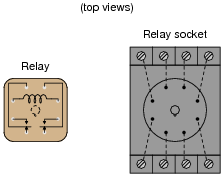
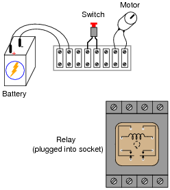
Small relays often come packaged in clear, rectangular, plastic cases, which had led to the name ice cube relay to be commonly applied to them. These so-called ïce cube" relays have either eight or eleven pins protruding from the bottom, allowing them to be plugged into a special socket for connection with wires in a circuit:
|
|
Draw the necessary connecting wires between terminals in this circuit, so that actuating the normally-open pushbutton switch will energize the relay, which will in turn supply electrical power to the motor.
|
|

|
|
Notes:
Ïce cube" style relays are very common in industry, and it is important that students understand how to interpret the pin diagrams on the cases in order to use them in new circuits and to troubleshoot relay circuits that are already built.
Question 9:
Suppose that an electromechanical relay has a coil voltage rating of 5 volts, and a coil resistance of 250 W. However, you desire to energize this relay with a 24 volt power supply. You know that a series-connected resistor might enable the 5-volt relay coil to be powered by the 24-volt supply without damage, but you do not know what size of resistor would be appropriate for the task.
Draw a schematic diagram for such a circuit, showing the power supply (battery symbol), relay, and resistor. Explain how the resistor's value would be calculated, along with the calculated value in ohms.
Notes:
Do not be surprised if many of your students neglect to calculate the resistor's necessary power dissipation rating for the resistor, simply because this value was not requested in the question. However, it is important for students to be actively thinking about every problem they encounter, and to try to take all relevant factors into consideration!
In real life, the power dissipation rating of such a resistor would be very important. Failing to account for this value could result in component (and system) failure.
Question 10:
Design an experimental circuit for determining the pull-in and drop-out current values for an electromagnetic relay coil. Why would these statistics matter to us, when working with relay circuits?
Notes:
The real challenge of this question, of course, is for the students to determine what in the world "pull-in" and "drop-out" current values are. Once these definitions have been found, it is a very simple matter to experimentally determine them for any given relay.
Question 11:
Find one or two relays and bring them with you to class for discussion. Identify as much information as you can about your relays prior to discussion:
- �
- Coil voltage
- �
- Coil resistance
- �
- Number of switch poles
- �
- Number of switch throws
- �
- Voltage rating of contacts
- �
- Current rating of contacts
Also, calculate the amount of current that will be drawn by the coil when energized.
If your relay's coil is designed for AC voltage rather than DC voltage, the amount of current drawn by it will be far less than what you have calculated by using Ohm's Law, due to a property of coils known as inductive reactance.
Notes:
The purpose of this question is to get students to kinesthetically interact with the subject matter. It may seem silly to have students engage in a ßhow and tell" exercise, but I have found that activities such as this greatly help some students. For those learners who are kinesthetic in nature, it is a great help to actually touch real components while they're learning about their function. Of course, this question also provides an excellent opportunity for them to practice interpreting component markings, use a multimeter, access datasheets, etc.