Electromechanical relay logic
Question 1:
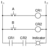
In ladder logic symbolism, an electromechanical relay coil is shown as a circle, and the contact(s) actuated by the coil as two parallel lines, almost like a capacitor symbol. Given this knowledge, interpret the following ladder logic diagram:
|
|
How do we know which relay contact is actuated by which relay coil? How does this convention differ from that of standard electrical/electronic schematic diagrams, where the relay coil is shown as an actual coil of wire (inductor symbol) with the contact "linked" to the coil by a dashed line? Also, what type of logic function behavior (AND, OR, NAND, or NOR) does the above circuit exhibit?
Notes:
Many students find it confusing that relay contacts and coils need not be drawn next to one another in a ladder logic diagram, because it is so different from the schematic diagrams they are accustomed to. The non-necessity of proximity in a ladder logic diagram does have its advantages, though! It is simply a matter of getting used to a new way of drawing things.
Question 2:
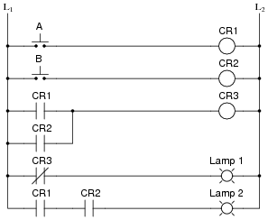
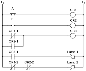
There is a problem somewhere in this relay logic circuit. Lamp 2 operates exactly as it should, but lamp 1 never turns on. Identify all possible failures in the circuit that could cause this problem, and then explain how you would troubleshoot the problem as efficiently as possible (taking the least amount of electrical measurements to identify the specific problem).
|
|
Notes:
Be sure to leave plenty of classroom time for a discussion on troubleshooting this circuit. Electrical troubleshooting is a difficult-to-develop skill, and it takes lots of time for some people to acquire. Being one of the most valuable skills a technical person can possess, it is well worth the time invested!
The challenge question is very practical. Too many times I have seen students take meter measurements when their other senses provide enough data to render that step unnecessary. While there is nothing wrong with using your meter to confirm a suspicion, the best troubleshooters use all their senses (safely, of course) in the isolation of system faults.
Question 3:
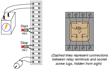
A very common application of electromechanical relay logic is motor control circuitry. Here is a ladder diagram for a simple DC motor control, where a momentary pushbutton switch starts the motor, and another pushbutton switch stops the motor:

|
|
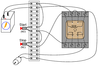
Translate this ladder diagram into point-to-point connections between the following components (shown in the following illustration):
|
|
|
|
Notes:
This circuit provides students with an opportunity to analyze a simple latch: a system that "remembers" prior switch actuations by holding a ßtate" (either set or reset; latched or unlatched). A simple motor start/stop circuit such as this is about as simple as latch circuits get.
Students should be able to immediately comprehend the benefit of using nice, neat, structured ladder diagrams when they see the tangled mess of wires in a real motor control circuit. And this is not even a complex motor control circuit! It takes very little imagination to think of something even uglier than this, and what a task it would be to troubleshoot such a circuit without the benefit of a ladder diagram for guidance.
Question 4:
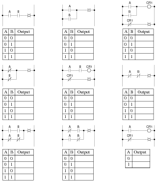
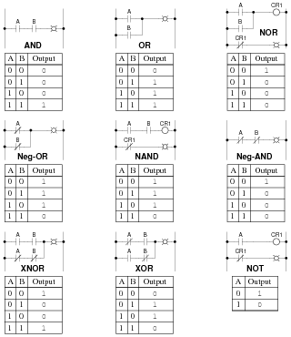
Identify each of these relay logic functions by name (AND, OR, NOR, etc.) and complete their respective truth tables:
|
|
|
|
Notes:
In order to familiarize students with standard switch contact configurations, I like to given them practice with identification and truth tables each day. Students need to be able to recognize these ladder logic sub-circuits at a glance, or else they will have difficulty analyzing more complex relay circuits that use them.
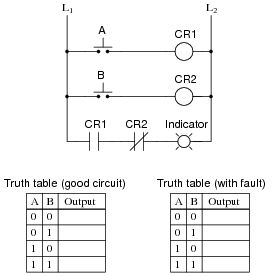
Question 5:
Predict how the operation of this relay logic circuit will be affected as a result of the following faults. Consider each fault independently (i.e. one at a time, no multiple faults):
|
|
- �
- Pushbutton switch A fails open:
- �
- Relay coil CR2 fails open:
- �
- Relay contact CR1-1 fails open:
- �
- Relay contact CR2-1 fails shorted:
- �
- Relay contact CR2-2 fails shorted:
For each of these conditions, explain why the resulting effects will occur.
- �
- Pushbutton switch A fails open: Lamp 1 always energized, lamp 2 simply becomes inverse status of pushbutton switch B.
- �
- Relay coil CR2 fails open: Both lamp 1 and lamp 2 simply become inverse status of pushbutton switch A.
- �
- Relay contact CR1-1 fails open: Lamp 1 simply becomes same status as pushbutton switch B.
- �
- Relay contact CR2-1 fails shorted: Lamp 1 always energized.
- �
- Relay contact CR2-2 fails shorted: Lamp 2 simply becomes inverse status of pushbutton switch A.
Notes:
The purpose of this question is to approach the domain of circuit troubleshooting from a perspective of knowing what the fault is, rather than only knowing what the symptoms are. Although this is not necessarily a realistic perspective, it helps students build the foundational knowledge necessary to diagnose a faulted circuit from empirical data. Questions such as this should be followed (eventually) by other questions asking students to identify likely faults based on measurements.
Question 6:
Though many electronics students and professionals alike associate semiconductor components with the word "digital," electromechanical relays are also digital logic (on or off) devices. In fact, some of the first digital computers were built with electromechanical relays as their active elements.
In what ways are electromechanical relays similar to semiconductor logic gates? In what ways do the two digital technologies differ?
Notes:
This question provides a good opportunity to review electromechanical relays: how they work, what they are used for, etc.
Question 7:
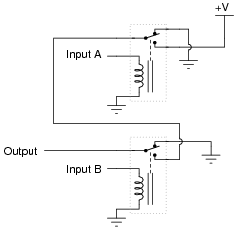
The following schematic is of a relay circuit that emulates a standard digital logic gate function:
|
|
Write a truth table for this circuit's function, and determine what name best represents it (AND, OR, NAND, NOR, or NOT).
Notes:
Ask your students to identify what arrangement the relay contacts are connected it: series or parallel? Does this contact arrangement make sense with regard to the established function of the gate?
Question 8:
The following schematic is of a relay circuit that emulates a standard digital logic gate function:

|
|
Write a truth table for this circuit's function, and determine what name best represents it (AND, OR, NAND, NOR, or NOT).
Notes:
Ask your students to identify what arrangement the relay contacts are connected it: series or parallel? Does this contact arrangement make sense with regard to the established function of the gate?
Question 9:
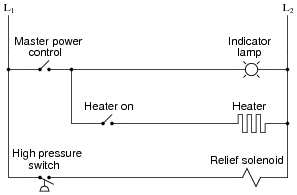
A type of electrical diagram convention optimal for representing electromechanical relay circuits is the ladder logic diagram. An example of a "ladder logic" diagram is shown here:
|
|
Each parallel circuit branch is represented as its own horizontal "rung" between the two vertical "rails" of the ladder. As you may have noticed, some of the symbols resemble standard electrical/electronic schematic symbols (toggle switches, for instance), while others are unique to ladder logic diagrams (heater elements, solenoid coils, lamps).
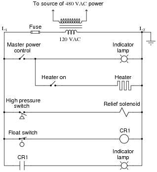
Where do the circuits shown obtain their electrical power? What do "L1" and "L2" represent? How are relay coils and contacts represented in a ladder logic diagram? Answer each of these questions by expanding upon the diagram shown above: draw the components necessary to show a complete electrical circuit (i.e. details of the power source), as well as an additional rung (or two) showing a relay coil actuated by some sort of switch contact, and the relay contact controlling power to a second indicator lamp.
|
|
"L1" and "L2" represent the "hot" and "neutral" lines, respectively, in a 120 volt AC power system. Often, the control circuit power is obtained from a step-down transformer, which is in turn fed by a higher voltage source (usually one phase of a 480 volt AC three-phase system, in American industrial applications).
Notes:
If students don't raise this point on their own, direct their attention to the relay coil and contact symbols. What looks strange here? What sort of electrical component are students familiar associating with the "CR1" contact symbol? Does it make sense to use this symbol to symbolize a normally-open switch (relay) contact? If we wished to show a normally-closed relay contact instead, how would we modify the diagram?
Question 10:
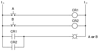
Complete the following ladder logic diagram so that an OR gate function is formed: the indicator lamp energizes if either switch A or switch B is actuated.

|
|
|
|
Notes:
Discuss with students the fact that relay coils and contacts need not be located near each other in ladder diagrams. While this may be confusing at times, it is a very flexible feature of ladder logic notation, because it gives the author the freedom to locate relay contacts where it makes the most visual sense in the öutput" rung of the diagram, without having to coordinate locations of coil and contact as is generally necessary in traditional schematic diagrams. Instead, relay contacts are associated with their respective coils by label, not by proximity on the diagram.
Question 11:
In ladder logic diagrams, a normally-open relay contact is drawn as a set of parallel lines, almost like a non-polarized capacitor in an electronic schematic diagram. Normally-closed relay contacts differ in symbolism by having a diagonal line drawn through them.
Analyze the following relay logic circuit, completing the truth table accordingly:
|
|
|
|
Notes:
Many students find the "line-through-the-contact" a very intuitive way to represent normally-closed relay contacts. Be sure to emphasize that the diagonal line, as well as the name normally-closed, does not refer to any given state of the contact, but rather to the contact's resting state when the relay coil is de-energized. I have seen teachers put a diagonal line through a relay contact symbol on a ladder logic diagram to indicate the state of the contact being closed by energization of the coil, during the process of explaining how a circuit functioned. This is wrong, as it confuses the concept of contacts being normally-closed with the concept of contacts simply being (energized) closed.
Question 12:
The following ladder logic diagram (for a steam heater control) contains a serious mistake:
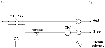
|
|
This is a mistake I've seen many students make. Explain what the mistake is, and draw a corrected version of this relay circuit.
Notes:
Discuss with your students why load devices are never to be connected in series. What would be the effect of doing so? Have them answer this question in terms of normal operation, and also in terms of operation given a failure condition in one of the series-connected load devices.
Question 13:
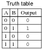
Complete the truth table for the following relay logic circuit, and then complete a second truth table for the same circuit with relay coil CR2 failed open:
|
|
Explain why the truth table will be modified as a result of the fault.
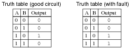
|
|
If you thought that the "faulted" truth table would be all 0's, you probably thought I said relay contact CR2 failed open. The fault I proposed was relay CR2 coil failed open.
Notes:
The purpose of this question is to approach the domain of circuit troubleshooting from a perspective of knowing what the fault is, rather than only knowing what the symptoms are. Although this is not necessarily a realistic perspective, it helps students build the foundational knowledge necessary to diagnose a faulted circuit from empirical data. Questions such as this should be followed (eventually) by other questions asking students to identify likely faults based on measurements.
Question 14:
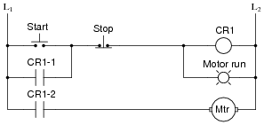
Predict how the operation of this motor control circuit will be affected as a result of the following faults. Consider each fault independently (i.e. one at a time, no multiple faults):
|
|
- �
- "Stop" pushbutton switch fails open:
- �
- Relay contact CR1-1 fails open:
- �
- Relay contact CR1-2 fails open:
- �
- Relay coil CR1 fails open:
For each of these conditions, explain why the resulting effects will occur.
- �
- "Stop" pushbutton switch fails open: Motor cannot start, lamp never energizes.
- �
- Relay contact CR1-1 fails open: Motor starts and lamp energizes when "Start" button is pressed, but both immediately de-energize when it is released.
- �
- Relay contact CR1-2 fails open: "Motor run" lamp turns on and off as expected, but the motor itself never runs.
- �
- Relay coil CR1 fails open: Motor cannot start, lamp never energizes.
Notes:
The purpose of this question is to approach the domain of circuit troubleshooting from a perspective of knowing what the fault is, rather than only knowing what the symptoms are. Although this is not necessarily a realistic perspective, it helps students build the foundational knowledge necessary to diagnose a faulted circuit from empirical data. Questions such as this should be followed (eventually) by other questions asking students to identify likely faults based on measurements.
Question 15:
Suppose you come across a relay that is said to have "Form C" contacts. What does this phrase mean? And, is there such a thing as either "Form A" or "Form B" contacts?
Notes:
When I first heard of a switch having "Form C" contacts, I had absolutely no idea what it meant. I was quite familiar with ßingle-pole, double-throw," but not this new term. Different industries often use different terms for describing the same things. Your students should be made aware that there is a tendency for people to become ïsolated" within their respective industries or fields of expertise, to the point where they may be unaware of alternative terms for the same things (Form-C versus SPST is a good example of this). Your students may even find themselves misjudged by others for not knowing the peculiar and specialized terms used within certain industries, when they first obtain employment. In many ways it is akin to the misunderstandings arising when different cultures meet: people have the general tendency to think their way of doing things is the only way. Bridging such cultural divides requires patience, humility, and tact.
Question 16:
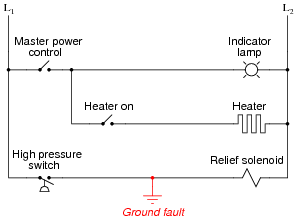
Safety is a paramount concern in electrical systems. Generally, we try to design electrical circuits so that if and when they fail, they will do so in the manner safest to those people working around them, and to the equipment and process(es) controlled by the circuit.
One of the more common failure modes of circuits having wires strung through metal conduit is the accidental ground, or ground fault, where the electrical insulation surrounding a wire fails, resulting in contact between that wire and a grounded metal surface.
Suppose an accidental ground were to occur at the point shown in this ladder diagram:
|
|
What would be the result of this fault? Hint: you will need to know something about the L1/L2 power source in order to answer this question!
What would be the result if the L1/L2 power connections were reversed?
Notes:
The ultimate purpose of this question is not to ascertain the effects of a particular fault so much as it is to derive a general rule regarding the construction of industrial control circuits. Students should be able to see the benefits of having L2 (the grounded power rail) on the right-hand side of the circuit, but can they induce the general safety principle to be applied in all control circuits? What is ßpecial" about having L2 on the right-hand side of the ladder diagram?
Question 17:
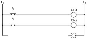
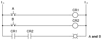
Complete the following ladder logic diagram so that an AND gate function is formed: the indicator lamp energizes if and only if both switch A and switch B are simultaneously actuated.
|
|
|
|
Notes:
Discuss with students the fact that relay coils and contacts need not be located near each other in ladder diagrams. While this may be confusing at times, it is a very flexible feature of ladder logic notation, because it gives the author the freedom to locate relay contacts where it makes the most visual sense in the öutput" rung of the diagram, without having to coordinate locations of coil and contact as is generally necessary in traditional schematic diagrams. Instead, relay contacts are associated with their respective coils by label, not by proximity on the diagram.
Question 18:
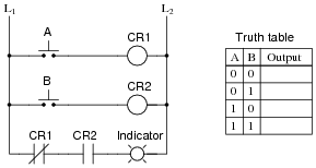
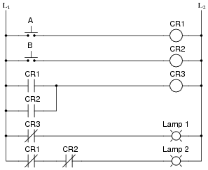
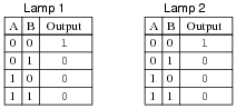
Write a truth table for each of the indicator lamps in the following ladder diagram, and determine which logic function (AND, OR, NAND, NOR, or NOT) best describes each lamp's behavior with respect to the status of the input switches.
|
|
|
|
Each of the lamps exhibits the behavior of a "NOR" gate.
Notes:
This question provides a good opportunity for students to practice analyzing relay logic circuits, and it also foreshadows DeMorgan's Theorem in its dual implementation of the NOR function. Note to your students how more than one contact is being used on control relays CR1 and CR2!
Question 19:
| Don't just sit there! Build something!! |
Learning to analyze relay circuits requires much study and practice. Typically, students practice by working through lots of sample problems and checking their answers against those provided by the textbook or the instructor. While this is good, there is a much better way.
You will learn much more by actually building and analyzing real circuits, letting your test equipment provide the änswers" instead of a book or another person. For successful circuit-building exercises, follow these steps:
- 1.
- Draw the schematic diagram for the relay circuit to be analyzed.
- 2.
- Carefully build this circuit on a breadboard or other convenient medium.
- 3.
- Check the accuracy of the circuit's construction, following each wire to each connection point, and verifying these elements one-by-one on the diagram.
- 4.
- Analyze the circuit, determining all logic states for given input conditions.
- 5.
- Carefully measure those logic states, to verify the accuracy of your analysis.
- 6.
- If there are any errors, carefully check your circuit's construction against the diagram, then carefully re-analyze the circuit and re-measure.
Always be sure that the power supply voltage levels are within specification for the relay coils you plan to use. I recommend using PC-board relays with coil voltages suitable for single-battery power (6 volt is good). Relay coils draw quite a bit more current than, say, semiconductor logic gates, so use a "lantern" size 6 volt battery for adequate operating life.
One way you can save time and reduce the possibility of error is to begin with a very simple circuit and incrementally add components to increase its complexity after each analysis, rather than building a whole new circuit for each practice problem. Another time-saving technique is to re-use the same components in a variety of different circuit configurations. This way, you won't have to measure any component's value more than once.
Notes:
It has been my experience that students require much practice with circuit analysis to become proficient. To this end, instructors usually provide their students with lots of practice problems to work through, and provide answers for students to check their work against. While this approach makes students proficient in circuit theory, it fails to fully educate them.
Students don't just need mathematical practice. They also need real, hands-on practice building circuits and using test equipment. So, I suggest the following alternative approach: students should build their own "practice problems" with real components, and try to predict the various logic states. This way, the relay theory "comes alive," and students gain practical proficiency they wouldn't gain merely by solving Boolean equations or simplifying Karnaugh maps.
Another reason for following this method of practice is to teach students scientific method: the process of testing a hypothesis (in this case, logic state predictions) by performing a real experiment. Students will also develop real troubleshooting skills as they occasionally make circuit construction errors.
Spend a few moments of time with your class to review some of the "rules" for building circuits before they begin. Discuss these issues with your students in the same Socratic manner you would normally discuss the worksheet questions, rather than simply telling them what they should and should not do. I never cease to be amazed at how poorly students grasp instructions when presented in a typical lecture (instructor monologue) format!
A note to those instructors who may complain about the "wasted" time required to have students build real circuits instead of just mathematically analyzing theoretical circuits:
What is the purpose of students taking your course?
If your students will be working with real circuits, then they should learn on real circuits whenever possible. If your goal is to educate theoretical physicists, then stick with abstract analysis, by all means! But most of us plan for our students to do something in the real world with the education we give them. The "wasted" time spent building real circuits will pay huge dividends when it comes time for them to apply their knowledge to practical problems.
Furthermore, having students build their own practice problems teaches them how to perform primary research, thus empowering them to continue their electrical/electronics education autonomously.
In most sciences, realistic experiments are much more difficult and expensive to set up than electrical circuits. Nuclear physics, biology, geology, and chemistry professors would just love to be able to have their students apply advanced mathematics to real experiments posing no safety hazard and costing less than a textbook. They can't, but you can. Exploit the convenience inherent to your science, and get those students of yours practicing their math on lots of real circuits!