Oscilloscope trigger controls
Question 1:
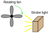
A very useful tool for observing rotating objects is a strobe light. Basically, a strobe light is nothing more than a very bright flash bulb connected to an electronic pulse generating circuit. The flash bulb periodically emits a bright, brief pulse of light according to the frequency set by the pulse circuit. By setting the period of a strobe light to the period of a rotating object (so the bulb flashes once per revolution of the object), the object will appear to any human observer to be still rather than rotating:
|
|
One problem with using a strobe light is that the frequency of the light pulses must exactly match the frequency of the object's rotation, or else the object will not appear to stand still. If the flash rate is mismatched, even by the slightest amount, the object will appear to slowly rotate instead of stand still.
Analog (CRT-based) oscilloscopes are similar in principle. A repetitive waveform appears to ßtand still" on the screen despite the fact that the trace is made by a bright dot of light constantly moving across the screen (moving up and down with voltage, and sweeping left to right with time). Explain how the sweep rate of an oscilloscope is analogous to the flash rate of a strobe light.
If an analog oscilloscope is placed in the "free-run" mode, it will exhibit the same frequency mismatch problem as the strobe light: if the sweep rate is not precisely matched to the period of the waveform being displayed (or some integer multiple thereof), the waveform will appear to slowly scroll horizontally across the oscilloscope screen. Explain why this happens.
Notes:
Really, the best way I've found for students to learn this principle is to experiment with a real oscilloscope and signal generator. I highly recommend setting up an oscilloscope and signal generator in the classroom during discussion time so that this may be demonstrated live.
Question 2:
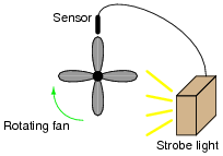
Suppose a metal-detecting sensor were connected to a strobe light, so that the light flashed every time a fan blade passed by the sensor. How would this setup differ in operation from one where the strobe light is free-running?
|
|
Follow-up question: how would the strobe light respond if the fan speed were changed? Explain your answer in detail.
Notes:
This question previews the concept of oscilloscope triggering: waiting until an event occurs before plotting the shape of a moving waveform. Often I find new students relate better to such mechanical analogies than directly to electronic abstractions when first learning oscilloscope operation.
An important detail to note in this scenario is that the strobe will flash four times per fan rotation!
Question 3:
The only way to consistently guarantee a repetitive waveform will appear ßtill" on an analog oscilloscope screen is for each left-to-right sweep of the CRT's electron beam to begin at the same point on the waveform. Explain how the "trigger" system on an oscilloscope works to accomplish this.
Notes:
Triggering is a complex feature for students to grasp in even simple analog oscilloscopes. Spend as much time with students as you must to give them understanding in this area, as it will be very useful in their labwork and eventually in their careers.
Question 4:
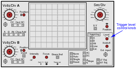
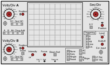
On this oscilloscope, identify the location of the trigger level control, and explain what it does:

|
|
|
|
Notes:
The location of the knob should be easy for students to determine. More difficult perhaps is the explanation of the knob's function.
Question 5:
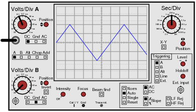
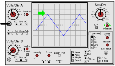
Suppose an oscilloscope has been set up to display a triangle wave:
|
|
The horizontal position knob is then turned clockwise until the left-hand edge of the waveform is visible:
|
|
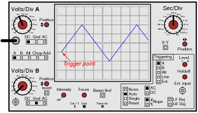
Now, the point at which the waveform triggers is clearly visible, no longer hidden from view past the left-hand side of the screen:
|
|
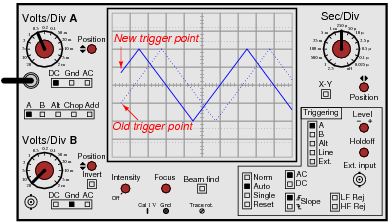
What will happen now if the trigger level knob is turned clockwise? How will this affect the positioning of the waveform on the oscilloscope screen?
|
|
Notes:
There is nothing special about a triangle wave here. To be perfectly honest, it was the easiest waveform for me to draw which had a sloping edge to trigger on!
By the way, for students to really understand how triggering works, it is important for them to spend time "playing" with an oscilloscope and a signal generator trying things like this. There is only so much one can learn about the operation of a machine by reading!
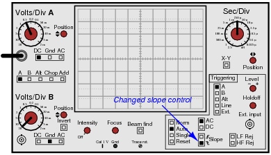
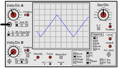
Question 6:
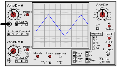
Suppose an oscilloscope has been set up to display a triangle wave, with the horizontal position control turned clockwise until the left-hand edge of the waveform is visible:
|
|
Then, the technician changes the slope control, changing it from ïncreasing" to "decreasing":
|
|
Draw the waveform's new appearance on the oscilloscope screen, with the slope control reversed.
|
|
Notes:
There is nothing special about a triangle wave here. To be perfectly honest, it was the easiest waveform for me to draw which had a sloping edge to trigger on!
By the way, for students to really understand how triggering works, it is important for them to spend time "playing" with an oscilloscope and a signal generator trying things like this. There is only so much one can learn about the operation of a machine by reading!
Question 7:
A student is experimenting with an oscilloscope, learning how to use the triggering control. While turning the trigger level knob clockwise, the student sees the effect it has on the waveform's position on the screen. Then, with an additional twist of the level knob, the waveform completely disappears. Now there is absolutely nothing shown on the screen! Turning the level knob the other way (counter-clockwise), the waveform suddenly appears on the screen again.
Based on the described behavior, does this student have the oscilloscope trigger control set on Auto mode, or on Norm mode? What would the oscilloscope do if the other triggering mode were set?
Notes:
Ask your students to explain which mode they think the oscilloscope should ordinarily be set in for general-purpose use.
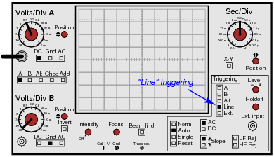
Question 8:
How will the oscilloscope trigger if the control is set to Line source rather than A or B inputs:
|
|
Follow-up question: what circumstance can you think of that would require this triggering source?
Notes:
"Line" triggering is a very useful feature, especially for working on line-powered and line-synchronized circuits. SCR- and TRIAC-based motor control circuits come immediately to mind here, as do brute-force (linear) power supply circuits!
Question 9:
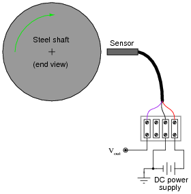
Large electric motors and other pieces of rotating machinery are often equipped with vibration sensors to detect imbalances. These sensors are typically linked to an automatic shutdown system so that the machine will turn itself off it the sensors detect excessive vibration.
Some of the more popular industrial-grade sensors generate a DC voltage proportional to the physical distance between the end of the sensor and the nearest metallic surface. A typical sensor installation might look like this:
|
|
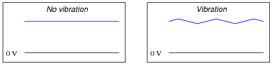
If the machine is running smoothly (or if it is shut down and not turning at all), the output voltage from the sensor will be pure DC, indicating a constant distance between the sensor end and the shaft surface. On the other hand, if the shaft becomes imbalanced it will bend ever so slightly, causing the distance to the sensor tip to periodically fluctuate as it rotates beneath the sensor. The result will be a sensor output signal that is an AC "ripple" superimposed on a DC bias, the frequency of that ripple voltage being equal to the frequency of the shaft's rotation:
|
|
The vibration sensing circuitry measures the amplitude of this ripple and initiates a shutdown if it exceeds a pre-determined value.
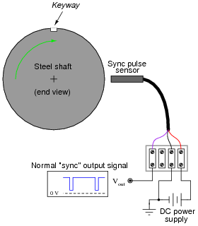
An additional sensor often provided on large rotating machines is a sync pulse sensor. This sensor works just like the other vibration sensors, except that it is intentionally placed in such a position that it ßees" a keyway or other irregularity on the rotating shaft surface. Consequently, the ßync" sensor outputs a square-wave "notch" pulse, once per shaft revolution:
|
|
The purpose of this ßync" pulse is to provide an angular reference point, so any vibration peaks seen on any of the other sensor signals may be located relative to the sync pulse. This allows a technician or engineer to determine where in the shaft's rotation any peaks are originating.
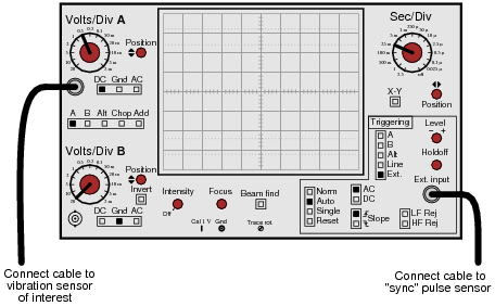
Your question is this: explain how you would use the sync pulse output to trigger an oscilloscope, so that every sweep of the electron beam across the oscilloscope's screen begins at that point in time.
|
|
Notes:
There are many electronic (non-mechanical) examples one could use to illustrate the use of external triggering. I like to introduce something like this once in a while to broaden students' thoughts beyond the world of tiny components and circuit boards. The practical applications of electronics are legion!
Question 10:
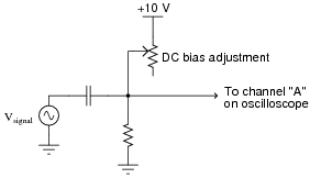
A student is trying to measure an AC waveform superimposed on a DC voltage, output by the following circuit:
|
|
The problem is, every time the student moves the circuit's DC bias adjustment knob, the oscilloscope loses its triggering and the waveform begins to wildly scroll across the width of the screen. In order to get the oscilloscope to trigger on the AC signal again, the student must likewise move the trigger level knob on the oscilloscope panel. Inspect the settings on the student's oscilloscope (shown here) and determine what could be configured differently to achieve consistent triggering so the student won't have to re-adjust the trigger level every time she re-adjusts the circuit's DC bias voltage:
|
|
Notes:
In order for students to successfully answer this question, they must grasp the function of the circuit itself. Discuss with them why and how the rheostat is able to change the amount of DC "bias" voltage imposed on the AC signal, then progress to discussing the oscilloscope's triggering.
Question 11:
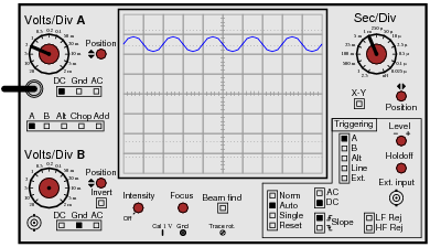
A student wants to measure the "ripple" voltage from an AC-DC power supply. This is the small AC voltage superimposed on the DC output of the power supply, that is a natural consequence of AC-to-DC conversion. In a well-designed power supply, this "ripple" voltage is minimal, usually in the range of millivolts peak-to-peak even if the DC voltage is 20 volts or more. Displaying this "ripple" voltage on an oscilloscope can be quite a challenge to the new student.
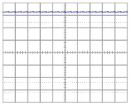
This particular student already knows about the AC/DC coupling controls on the oscilloscope's input. Set to the "DC" coupling mode, the ripple is a barely-visible squiggle on an otherwise straight line:
|
|
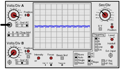
After switching the input channel's coupling control to ÄC", the student increases the vertical sensitivity (fewer volts per division) to magnify the ripple voltage. The problem is, the ripple waveform is not engaging the oscilloscope's triggering. Instead, all the student sees is a blur as the waveform quickly scrolls horizontally on the screen:
|
|
Explain what setting(s) the student can change on the oscilloscope to properly trigger this waveform so it will "hold still" on the screen.
Notes:
This is a very realistic scenario, one that your students will surely encounter when they build their own AC-DC power supply circuits. Ripple voltage, being such a small AC quantity superimposed on such a (relatively) large DC bias, is quite a challenge for the new student to "lock in" on his or her oscilloscope screen.
Be sure to discuss options other than line triggering. Also be sure to discuss why line triggering works in this situation. It is not a panacea for triggering all low-amplitude waveforms, by any means! It just happens to work in this scenario because the ripple voltage is a direct function of the AC line voltage, and as such is harmonically related.
Question 12:
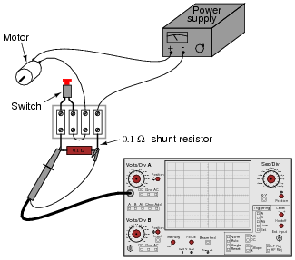
All electric motors exhibit a large ïnrush" current when initially started, due to the complete lack of counter-EMF when the rotor has not yet begun to turn. In some applications it is very important to know how large this transient current is. Shown here is a measurement setup for an oscilloscope to graph the inrush current to a DC motor:
|
|
Explain how this circuit configuration enables the oscilloscope to measure motor current, when it plainly is a voltage-measuring instrument.
Also, explain how the oscilloscope may be set up to display only one ßweep" across the screen when the motor is started, and where the vertical and horizontal sensitivity knobs ought to be set to properly read the inrush current.
In order to display only one ßweep," the oscilloscope triggering needs to be set to single mode. By the way, this works exceptionally well on digital-storage oscilloscopes, but not as well on analog oscilloscopes.
There are no ëasy" answers for how to set the vertical and horizontal controls. Issues to consider (and discuss in class!) include:
- �
- Expected inrush current (several times full-load current)
- �
- Scaling factor provided by resistive shunt
- �
- Typical ramp-up time for motor, in seconds
Challenge question: the larger the shunt resistor value, the stronger the signal received by the oscilloscope. The smaller the shunt resistor value, the weaker the signal received by the oscilloscope, making it difficult to accurately trigger on and measure the current's peak value. Based on this information, one might be inclined to choose the largest shunt resistor size available - but doing so will cause other problems. Explain what those other problems are.
Notes:
This question came from direct, personal experience. I was once working on the construction of a servo motor control system for positioning rotary valves, and we were having problems with the motors tripping the overcurrent limits upon start-up. I needed to measure the typical inrush current magnitude and duration. Fortunately, I had a digital storage oscilloscope at my disposal, and I set up this very circuit to do the measurements. About a half-hour of work setting up all the components, and I had the information I needed. The digital oscilloscope also provided me with digital ßcreenshot" images that I could email to engineers working on the project with me, so they could see the same data I was seeing.
Question 13:
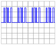
Suppose you were looking at this waveform in an oscilloscope display:
|
|
This is a difficult waveform to trigger, because there are so many identical leading and trailing edges to trigger from. No matter where the trigger level control is set, or whether it is set for rising- or falling-edge, the waveform will tend to "jitter" back and forth horizontally on the screen because these controls cannot discriminate the first pulse from the other pulses in each cluster of pulses. At the start of each ßweep," any of these pulses are adequate to initiate triggering.
One triggering control that is helpful in stabilizing such a waveform is the trigger holdoff control. Explain what this control does, and how it might work to make this waveform more stable on the screen.
Notes:
A purposefully minimal answer (as usual!) is shown in the answer section for this question. Understanding how holdoff works may very well require hands-on experience for some students, so I highly recommend setting up a demonstration in the classroom to use while discussing this oscilloscope feature.
Question 14:
A technician is measuring two waveforms of differing frequency at the same time on a dual-trace oscilloscope. The waveform measured by channel Ä" seems to be triggered just fine, but the other waveform (channel "B") appears to be untriggered: the waveshape slowly scrolls horizontally across the screen as though the trace were free-running.
This presents a problem for the technician, because channel B's waveform is the more important one to have "locked" in place for viewing. What should the technician do to make channel B's display stable?
Follow-up question: if the above advice is taken, channel B's waveform will become "locked" in place, but channel A's waveform will now begin to scroll across the screen. Is there any way to lock both waveforms in place so neither one appears to scroll across the screen?
Notes:
Like so many oscilloscope principles, this is perhaps best understood through actually using an oscilloscope. Try to set up two signal generators and an oscilloscope in your classroom so that you may demonstrate these controls while discussing them with your students.
Question 15:
Another challenging sort of waveform to "lock in" on an oscilloscope display is one where a high-frequency waveform is superimposed on a low-frequency waveform. If the two frequencies are not integer multiples (harmonics) of each other, it will be impossible to make both of them hold still on the oscilloscope display.
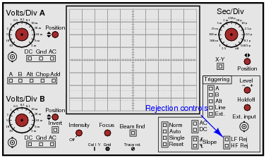
However, most oscilloscopes have frequency-specific rejection controls provided in the trigger circuitry to help the user discriminate between mixed frequencies. Identify these controls on the oscilloscope panel, and explain which would be used for what circumstances.
|
|
|
|
Follow-up question: identify the filter circuits internal to the oscilloscope associated with each of these "rejection" controls.
Notes:
Finding the controls on the oscilloscope panel should present no difficulty for most students, at least once they realize what the controls are called. The key to answering this question is to research the words "rejection" and "trigger" in the context of oscilloscope controls.