Servo motor systems
Question 1:
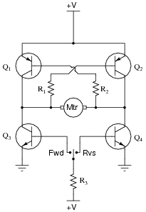
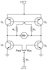
Explain the operation of this "H-bridge" motor control circuit:

|
|
At any given moment, how many transistors are turned on and how many are turned off? Also, explain what would happen to the function of the circuit if resistor R1 failed open.
Challenge question: what type of DC motor is this drive circuit designed for? Shunt-wound, series-wound, compound, or permanent magnet? Explain your answer.
Notes:
The "H-drive" circuit is a very common method of reversing polarity to a DC motor (or other polarity-sensitive load), using only a single-pole switch. Very, very large electric motor "drives" have been based on this same design.
Question 2:
Predict how the motor function in this circuit will be affected as a result of the following faults. Consider each fault independently (i.e. one at a time, no multiple faults):
|
|
- �
- Transistor Q1 fails open (collector-to-emitter):
- �
- Transistor Q2 fails open (collector-to-emitter):
- �
- Transistor Q3 fails open (collector-to-emitter):
- �
- Transistor Q4 fails open (collector-to-emitter):
- �
- Resistor R1 fails open:
- �
- Resistor R2 fails open:
- �
- Resistor R3 fails open:
- �
- Transistor Q3 fails shorted (collector-to-emitter):
- �
- Transistor Q4 fails shorted (collector-to-emitter):
For each of these conditions, explain why the resulting effects will occur.
- �
- Transistor Q1 fails open (collector-to-emitter): Motor fails to turn in "reverse" direction, can still turn in "forward" direction.
- �
- Transistor Q2 fails open (collector-to-emitter): Motor fails to turn in "forward" direction, can still turn in "reverse" direction.
- �
- Transistor Q3 fails open (collector-to-emitter): Motor fails to turn in "forward" direction, can still turn in "reverse" direction.
- �
- Transistor Q4 fails open (collector-to-emitter): Motor fails to turn in "reverse" direction, can still turn in "forward" direction.
- �
- Resistor R1 fails open: Motor fails to turn in "forward" direction, can still turn in "reverse" direction.
- �
- Resistor R2 fails open: Motor fails to turn in "reverse" direction, can still turn in "forward" direction.
- �
- Resistor R3 fails open: Motor cannot turn in either direction.
- �
- Transistor Q3 fails shorted (collector-to-emitter): Motor turns in "forward" direction even when the switch is in the center (off) position.
- �
- Transistor Q4 fails shorted (collector-to-emitter): Motor turns in "reverse" direction even when the switch is in the center (off) position.
Notes:
The purpose of this question is to approach the domain of circuit troubleshooting from a perspective of knowing what the fault is, rather than only knowing what the symptoms are. Although this is not necessarily a realistic perspective, it helps students build the foundational knowledge necessary to diagnose a faulted circuit from empirical data. Questions such as this should be followed (eventually) by other questions asking students to identify likely faults based on measurements.
Question 3:
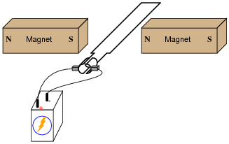
If the ends of a wire loop are attached to two half-circular metal strips, arranged so that the two strips almost form a complete circle, and those strips are contacted by two "brushes" which connect to opposite poles of a battery, which way will the wire loop rotate?
|
|
Notes:
Challenge your students with this question: is there any way we can get the wire loop to continuously rotate without using those half-circle metal strips to make and break contact with the battery? Ask your students what the two half-circle metal strips are called, in electric motor/generator terminology.
Question 4:
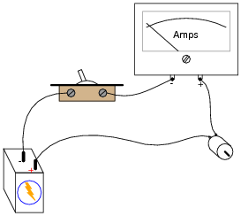
When the switch closes, the ammeter will initially register a large amount of current, then the current will decay to a much lesser value over time as the motor speeds up:
|
|
In view of Ohm's Law, where current is supposed to be a direct function of voltage and resistance (I = E/R), explain why this happens. After all, the motor's winding resistance does not change as it spins, and the battery voltage is fairly constant. Why, then, does the current vary so greatly between initial start-up and full operating speed?
What do you think the ammeter will register after the motor has achieved full (no-load) speed, if a mechanical load is placed on the motor shaft, forcing it to slow down?
Follow-up question: draw a schematic diagram showing the equivalent circuit of battery, switch, ammeter, and motor, with the counter-EMF of the motor represented as another battery symbol. Which way must the counter-EMF voltage face, opposed to the battery voltage, or aiding the battery voltage?
Notes:
The so-called ïnrush" current of an electric motor during startup can be quite substantial, upwards of ten times the normal full-load current!
Question 5:
A DC electric motor spinning at 4500 RPM draws 3 amps of current with 110 volts measured at its terminals. The resistance of the armature windings, measured with an ohmmeter when the motor is at rest, unpowered, is 2.45 ohms. How much counter-EMF is the motor generating at 4500 RPM?
How much ïnrush" current will there be when the motor is initially powered up (armature speed = 0 RPM), once again assuming 110 volts at the terminals?
Iinrush = 44.9 A
Notes:
This calculation helps students realize just how significant the ïnrush" current of an electric motor is.
Question 6:
Explain what a servo motor system is, in your own words.
Notes:
Servos come in many different types and sizes, but they all share similar characteristics. Your students should have no problem at all finding information on them.
Question 7:
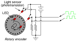
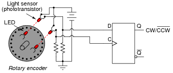
A common type of rotary encoder is one built to produce a quadrature output:
|
|
The two LED/phototransistor pairs are arranged in such a way that their pulse outputs are always 90o out of phase with each other. Quadrature output encoders are useful because they allow us to determine direction of motion as well as incremental position.
Building a quadrature direction detector circuit is easy, if you use a D-type flip-flop:
|
|
Analyze this circuit, and explain how it works.
Follow-up question: comment on the notation used for this circuit's output. What does the label "CW /[`CCW]" tell you, without having to analyze the circuit at all?
Notes:
Quadrature direction-detection circuits such as this become important when encoders are linked to digital counter circuits. The complemented notation is also very common in counter circuits.
Students may show a reluctance to draw a timing diagram when they approach this problem, even when they realize the utility of such a diagram. Instead, many will try to figure the circuit out just by looking at it. Note the emphasis on the word "try." This circuit is much more difficult to figure out without a timing diagram! Withhold your explanation of this circuit until each student shows you a timing diagram for it. Emphasize the fact that this step, although it consumes a bit of time, is actually a time-saver in the end.
Question 8:
Radio-controlled toy cars, airplanes, and boats use small servo motors for positioning of the steering mechanisms, engine throttle position, and such. These servos have the motor, position sensor, and control electronics housed in the same plastic package, making them very compact.
Research the type(s) of control signals used to command these servo units. In other words, find out what sort of electronic signal they require to "command" them to go to certain positions. Then, suggest a circuit that could generate these signals.
Notes:
The availability of inexpensive RC servos makes them ideal for use in lab experiments and student projects. It is well worth your students' time (and yours!) to find out how these amazing little devices are controlled!
Question 9:
Determine all component voltage drops in this circuit when the motor is operating in the reverse direction. Be sure to explain how you performed all the analyses! Assume 0.7 volts as the standard forward voltage drop for a forward-biased PN junction, and 0.3 volts as the standard collector-to-emitter voltage drop for a saturated BJT.
|
|
Challenge question: what type of DC motor must this be, to be reversed in rotational direction by a reversal of polarity?
Notes:
The primary purpose of this question is to give students more practice using Kirchhoff's Voltage Law. Be sure to work through the analysis of all component voltage drops.