Stepper motors
Question 1:
| Don't just sit there! Build something!! |
Learning to analyze digital circuits requires much study and practice. Typically, students practice by working through lots of sample problems and checking their answers against those provided by the textbook or the instructor. While this is good, there is a much better way.
You will learn much more by actually building and analyzing real circuits, letting your test equipment provide the änswers" instead of a book or another person. For successful circuit-building exercises, follow these steps:
- 1.
- Draw the schematic diagram for the digital circuit to be analyzed.
- 2.
- Carefully build this circuit on a breadboard or other convenient medium.
- 3.
- Check the accuracy of the circuit's construction, following each wire to each connection point, and verifying these elements one-by-one on the diagram.
- 4.
- Analyze the circuit, determining all output logic states for given input conditions.
- 5.
- Carefully measure those logic states, to verify the accuracy of your analysis.
- 6.
- If there are any errors, carefully check your circuit's construction against the diagram, then carefully re-analyze the circuit and re-measure.
Always be sure that the power supply voltage levels are within specification for the logic circuits you plan to use. If TTL, the power supply must be a 5-volt regulated supply, adjusted to a value as close to 5.0 volts DC as possible.
One way you can save time and reduce the possibility of error is to begin with a very simple circuit and incrementally add components to increase its complexity after each analysis, rather than building a whole new circuit for each practice problem. Another time-saving technique is to re-use the same components in a variety of different circuit configurations. This way, you won't have to measure any component's value more than once.
Notes:
It has been my experience that students require much practice with circuit analysis to become proficient. To this end, instructors usually provide their students with lots of practice problems to work through, and provide answers for students to check their work against. While this approach makes students proficient in circuit theory, it fails to fully educate them.
Students don't just need mathematical practice. They also need real, hands-on practice building circuits and using test equipment. So, I suggest the following alternative approach: students should build their own "practice problems" with real components, and try to predict the various logic states. This way, the digital theory "comes alive," and students gain practical proficiency they wouldn't gain merely by solving Boolean equations or simplifying Karnaugh maps.
Another reason for following this method of practice is to teach students scientific method: the process of testing a hypothesis (in this case, logic state predictions) by performing a real experiment. Students will also develop real troubleshooting skills as they occasionally make circuit construction errors.
Spend a few moments of time with your class to review some of the "rules" for building circuits before they begin. Discuss these issues with your students in the same Socratic manner you would normally discuss the worksheet questions, rather than simply telling them what they should and should not do. I never cease to be amazed at how poorly students grasp instructions when presented in a typical lecture (instructor monologue) format!
I highly recommend CMOS logic circuitry for at-home experiments, where students may not have access to a 5-volt regulated power supply. Modern CMOS circuitry is far more rugged with regard to static discharge than the first CMOS circuits, so fears of students harming these devices by not having a "proper" laboratory set up at home are largely unfounded.
A note to those instructors who may complain about the "wasted" time required to have students build real circuits instead of just mathematically analyzing theoretical circuits:
What is the purpose of students taking your course?
If your students will be working with real circuits, then they should learn on real circuits whenever possible. If your goal is to educate theoretical physicists, then stick with abstract analysis, by all means! But most of us plan for our students to do something in the real world with the education we give them. The "wasted" time spent building real circuits will pay huge dividends when it comes time for them to apply their knowledge to practical problems.
Furthermore, having students build their own practice problems teaches them how to perform primary research, thus empowering them to continue their electrical/electronics education autonomously.
In most sciences, realistic experiments are much more difficult and expensive to set up than electrical circuits. Nuclear physics, biology, geology, and chemistry professors would just love to be able to have their students apply advanced mathematics to real experiments posing no safety hazard and costing less than a textbook. They can't, but you can. Exploit the convenience inherent to your science, and get those students of yours practicing their math on lots of real circuits!
Question 2:
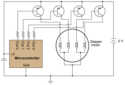
In this circuit, a microcontroller controls the rotation of a special type of motor known as a stepper motor by sequentially activating one transistor at a time (thus, energizing one motor coil at a time). With each step in the sequence, the motor rotates a fixed number of degrees, typically 1.8 degrees per step:
|
|
Each motor coil draws a relatively heavy current when energized, necessitating transistors to ïnterpose" between the microcontroller outputs and the motor coils.
Identify what type of logical signal ("high" or "low") from the output ports of the microcontroller is needed to energize each transistor. Also, show how the power losses and parts count may be reduced by replacing each bipolar junction transistor with a suitable MOSFET in the following diagram:

|
|

|
|
Follow-up question: if the resistors had to be left in place, would the modified (MOSFET instead of BJT) circuit still function properly?
Notes:
The purpose of this long-winded question is not just to have students figure out how to replace a BJT with a MOSFET, but also to introduce them to the concept of the microcontroller, which is a device of increasing importance in modern electronic systems.
No commutating diodes have been shown in this circuit, for simplicity's sake. If any students ask about this, commend them for noticing!
Question 3:
Stepper motor coils typically draw a lot of current, requiring the use of power transistors to "buffer" the control circuitry to the motor. A typical stepper motor final drive circuit looks something like this (only one of the four output transistors is shown, for brevity):

|
|
The diode is installed, of course, to prevent high-voltage surges from destroying the output transistor each time it turns off. However, this causes a different problem: with the free-wheeling diodes in place, the magnetic field formed in each coil takes longer to "decay" when its respective transistor turns off. This delay in time imposes a maximum rotational speed on the stepper motor, because the motor will not move to the next step until the magnetic field(s) from the previous step have dissipated.
What modification may be made to this circuit to allow the transistors to switch faster, driving the stepper motor at a higher rotational speed? Explain in detail why your solution will work.

|
|
I won't explain exactly why this solution works, but I'll let Michael Faraday give you a mathematical "hint:"
|
Follow-up question: what factors determine the resistance value of the new resistor shown in the diagram?
Challenge question: determine how to calculate the magnitude of the voltage ßpike" seen at the transistor's collector terminal given a certain resistance value, diode specifications, and full-load motor coil current.
Notes:
Ask your students to describe the rate-of-change of magnetic flux in each coil upon transistor turn-off, with no commutating diodes in place (assuming the transistor could withstand the transient voltages produced by the inductor). It should become clear to your students that the inclusion of diodes to prevent the high-voltage ßpikes" literally creates the problem of magnetic field decay time.
Question 4:
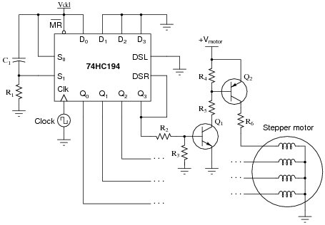
This shift register circuit drives the four coils of a unipolar stepper motor, one at a time, in a rotating pattern that moves at the pace of the clock. The drive transistor circuitry (Q1, Q2, and resistors R2 through R6) are shown only for one of the four coils. The other three shift register outputs have identical drive circuits connected to the respective motor coils:
|
|
Suppose this stepper motor circuit worked just fine for several years, then suddenly stopped working. Explain where you would take your first few measurements to isolate the problem, and why you would measure there.
Notes:
This is a good question to discuss with your students, as it helps them understand how to "divide and conquer" a malfunctioning system.
Question 5:
Stepper motors are often used in low-power servomechanisms such as those found in small robots, computer printers, and other precision electro-mechanical machines. Explain why this type of electric motor is more popular than permanent-magnet DC motors or other motor types. Hint: the answer is closely related to the name of the motor itself (ßtepper").
Notes:
Make sure students get a chance to feel the motion of a stepper motor in their own hands when you discuss stepper motors in class. If you don't happen to have any stepper motors available, they are easily obtained by salvaging parts from worn-out computer printers!